Table of Contents
Advertisement
Advertisement
Table of Contents

Related Manuals for Kobold NGM


Summary of Contents for Kobold NGM
- Page 1 Operating Instructions Guided Wave Radar Level Transmitter (TDR) Model: NGM...
- Page 2 The document may contain technical inaccuracies and typographical errors. The content will be revised on a regular basis. These changes will be implemented in later versions. The described products can be improved and changed at any time without prior notice. page 2 NGM K09/0717...
-
Page 3: Table Of Contents
............ 18 disturbance signal scan ..............19 Guide to communicating from a PC to a NGM probe ......20 (Configuration of device specific parameters) ..........20 Technical Information .................. 46 ... -
Page 4: Note
EC-machine guidelines. This quick installation guide gives instructions for mounting, wiring, and basic configuration of NGM. This will be sufficient to achieve a fully functional sensor in most applications. For further details and advanced configuration of NGM, please contact your local distributor or KOBOLD directly. -
Page 5: Operating Principle
6. Mechanical Connection 6.1 Mounting In case NGM is delivered with a detached probe, attach the probe onto the small threaded stud below the hexagon. Ensure that you mount the counter nut first to secure the probe connection: it has to be interlocked against the probe, NOT against the plastic of the feedthrough (this would result in sheering off the small threaded stud;... -
Page 6: Extended Temperature Range
NGM. Welding on the metal parts of NGM will cause serious damage to the sensor. Do not lift or handle NGM by its probe; this can cause excessive stress on the probe connection. NGM should be handled by the hexagon or the lower section of the housing. -
Page 7: Ptfe Coated Single Rod Probe
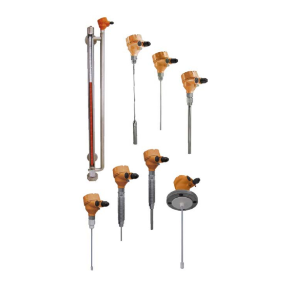
The anchoring fixtures are customer supplied. For further details about mounting NGM or if you would like to anchor the probes, please contact your local distributor or KOBOLD directly. single rod / wire rope probe... - Page 8 The single rod probe is also the recommended probe type for mounting NGM into bypass chambers or stilling wells. In this case, plastic centering disks are needed to prevent the probe from contacting the wall.
-
Page 9: Cable Entries And Cable Glands
The coaxial probe is recommended for installing NGM into a non-metallic tank or open pit. If that is not possible, single rod or wire rope probes can be used when NGM is mounted into at least a DN50 metal flange or screwed into a metal sheet with at least Ø150mm. -
Page 10: Electrical Connection
Figure 7: lower sticker on the black plastic cartridge Verify that the power supply for the sensor is switched off. Establish an equipotential connection (potential equalization) between the external earth terminal of NGM and the closest ground potential terminal of the tank. page 10... - Page 11 (during this start-up time the LED is solid green). The blinking green LED indicates that the sensor is in measuring mode and working correctly. Do not tighten the housing cover yet. Some basic configuration is still to be done… NGM K09/0717 page 11...
-
Page 12: Operation / Configuration / Adjustments
DCS or PLC HART modem computer power supply Figure 8: wiring 8. Operation / Configuration / Adjustments 8.1 Control Elements DIP switch off/0 on/1 push button Figure 9: Control Elements page 12 NGM K09/0717... - Page 13 LED blinking alternately green and red. When DIP switch position 8 is off/0, NGM is in measuring mode; indicated by the LED blinking green. It is only possible to enter the configuration mode when DIP switch positions 1 to 7 are off/0 before setting DIP switch position 8 to on/1;...
-
Page 14: Configuration Single Rod Probe Or Wire Rope Probe
For most standard applications, executing the three basic configuration steps below issufficient to achieve a fully functional sensor; providing a continuous level measurement through its analog current output. For further details and advanced configuration of NGM, please contact your local distributor or KOBOLD directly. page 14... - Page 15 8.2.1 perform disturbance signal scan NGM has to be mounted in its final position and the tank has to be completely empty in order to perform a disturbance signal scan set the DIP switch positions to the 0/1 sequence in Fig. 11on the left; start from position 8 and move towards position 1! ...
- Page 16 If desired, tighten the cover locking screw with an allen key size 1,5mm. DIP switch Position 1 2 3 4 5 6 7 DIP switch settings description 0 0 0 0 0 0 0 measuring mode Figure 14: measuring mode page 16 NGM K09/0717...
-
Page 17: Configuration Coaxial Probe
The coaxial probe has a very robust and reliable measurement performance in almost any application without further configuration. For basic configuration only the range values for the analogue current output have to be set. For further details and advanced configuration of NGM, please contact your local distributor or KOBOLD directly. 8.3.1 lower range value [4MA];... -
Page 18: Probe Length And Measuring Range
(i.e. dielectric constant) of the liquid to be measured. The measuring range [M] of NGM extends between the top and bottom inactive areas of the probe; this is the area in which NGM will have the specified measurement performance. It is recommended that the maximum and minimum liquid levels to be measured in the tank are actually within the measuring range [M] of the sensor. -
Page 19: Disturbance Signal Scan
The disturbance signal scan works most efficiently on stationary interference targets like tall and narrow nozzles or close-by objects. Thus, NGM has to be mounted in its final position and the tank has to be completely empty in order to perform a disturbance signal scan;... -
Page 20: Guide To Communicating From A Pc To A Ngm Probe
Requirements: - PC with Microsoft Office - Excel file NGM Configuration Tool LA (HART) V172.xls (for serial no. below 335490 (non-Ex) and serial no. below E5048 (Ex)) - Excel file NGM Configuration Tool LA (HART) V175.xls (from serial no. 335490 (non-Ex) and serial no. - Page 21 8.6.2 Connection of a NGM Probe to a PC • Check the COM port assignment of the PC to the USB HART modem with the Device Manager http://www.computerhope.com/issues/ch000833.htm * In this case COM port 4 has been assigned to the HART modem...
- Page 22 For the usage of the Excel tool, a click on the necessary cell activates the communication and/or parameters can be changed. For re-sending the command, click on a free cell elsewhere and move back to the required cell. The OK status has to return for a successful communication. page 22 NGM K09/0717...
- Page 23 If OK status does not reappear, check the connection or the COM port settings Now the HART communication is established and the modification of device- specific parameter as well as the read-out of the echo curve can be performed. NGM K09/0717 page 23...
- Page 24 • Change actual 4…20mA settings by changing the values in G4 and G5 and clicking on I4 and I5 “set lower / upper range value” • Verify changes by clicking again on I6 and I7 “get lower / upper range value” Reference point = 0mm page 24 NGM K09/0717...
- Page 25 G8 and clicking on I8 “set response time”. Use high response times for storage tanks with slow level movements. Use low response times for buffer and process tanks. Verify changes by clicking again on I9 “get response time” NGM K09/0717 page 25...
- Page 26 “normally closed”, as it would open at a power failure for highest safety. • Change actual switching output mode 0 or 1 in field G10 and clicking on I10 “set switching output mode” Verify changes by clicking again on I11 “get switching output mode” page 26 NGM K09/0717...
- Page 27 • Change actual lower / upper threshold in field G12 / G14 and click on I12 / I14 “set lower / upper threshold switching output mode”. Verify changes by clicking again on I13 / I15 “get lower / upper threshold switching output” NGM K09/0717 page 27...
- Page 28 • Change actual upper dead band in field G16 and click on I16 “set upper dead band”. Verify changes by clicking again on I17 “get upper dead band” page 28 NGM K09/0717...
- Page 29 The level reflection should be always 1/3 bigger than the width of the amplitude threshold band. • Change actual amplitude threshold in field G18 and click on I18 “set amplitude threshold”. Verify changes by clicking again on I19 “get amplitude threshold” NGM K09/0717 page 29...
- Page 30 • Change actual disturbance signal scan status in field G20 and click on I20 “set disturbance signal scan status” • Once changing it to “10” or “01” a disturbance signal scan must be performed with I22. Verify changes by clicking again on I21 “get disturbance signal scan status” page 30 NGM K09/0717...
- Page 31 1= single probe rod or rope Thresholds are adapted automatically by changing this parameter. • Change actual probe type in field G23 and click on I23 “set probe type”. Verify changes by clicking again on I24 “get probe type” NGM K09/0717 page 31...
- Page 32 • Read out actual probe length, by clicking on I26. Field G26 indicates the actual probe length in mm. • Change actual probe length in field G25 and click on I25 “set probe length”. Verify changes by clicking again on I26 “get probe length” page 32 NGM K09/0717...
- Page 33 8.6.13 Set Delivery Configuration BASIC CONFIGURATION • Set actual parameters as delivery configuration by clicking on I27 Former delivery configuration parameters will be overwritten! No reset to factory conditions is possible anymore. UNDO NOT POSSIBLE! NGM K09/0717 page 33...
- Page 34 Reset unit back to delivery configuration, by clicking on I28. 4…20mA, response time, switching mode and thresholds, upper dead band, amplitude threshold, disturbance scan, probe type, and probe length will be set back to delivery configuration. UNDO NOT POSSIBLE! page 34 NGM K09/0717...
- Page 35 If you do not measure the current output in series with a Multimeter, it is recommended to read out the level 3 – 5 times to recognize potential current fluctuations. If a fluctuating current can be observed, the amplitude threshold or dead band needs to be adjusted. NGM K09/0717 page 35...
- Page 36 8.6.16 Software Revision BASIC CONFIGURATION • Get actual software revision, by clicking on I30. As of April 30, 2013, the actual software revision is V150. For an upgrade please contact KOBOLD. page 36 NGM K09/0717...
- Page 37 8.6.17 Device Status BASIC CONFIGURATION • Get actual devise status, by clicking on I31. Important probe status information can be communicated. Click on the small red upper right corner for more details. NGM K09/0717 page 37...
- Page 38 Once the OK status in field H32 does not disappear anymore, the echo curve can be visualized by clicking on worksheet SIGNAL. Reading out the echo curve from the electronics can take several seconds, as all data must be communicated via the serial HART protocol to the PC. page 38 NGM K09/0717...
- Page 39 Depending on the probe length, the range within the echo curve in worksheet SIGNAL can be adapted. A negative X1 range of -1000 is always recommended and standard. With this the microwave generation and coupling can be verified. NGM K09/0717 page 39...
- Page 40 SIGNAL • Visualization of the actual echo curve, where the level calculation is based on. • The NGM gets 70 echo curves every second for calculating the level. The most important parameters (4…20mA; dead band and amplitude threshold) are visualized.
- Page 41 8.6.21 More Parameters… ADVANCED CONFIGURATION • Parameters within the worksheet ADVANCED CONFIGURATION are only recommended to change by experts. NGM K09/0717 page 41...
- Page 42 • Perfect coupling into the coaxial probe • Positive end of probe reflection which corresponds to the physical end of probe Dead band parameter at 30mm. 20mA parameter at 50mm. 4mA parameter at 230mm. Amplitude threshold at 1000. page 42 NGM K09/0717...
- Page 43 • Negative level reflection at 168mm • No end of probe reflection as energy is completely reflected at water surface Dead band parameter at 30mm. 20mA parameter at 50mm. 4mA parameter at 230mm. Amplitude threshold at 1000. NGM K09/0717 page 43...
- Page 44 • Reflection can change with mounting conditions. • Positive end of probe reflection which corresponds to the physical end of probe Dead band parameter at 30mm. 20mA parameter at 50mm. 4mA parameter at 230mm. Amplitude threshold at 1000. page 44 NGM K09/0717...
- Page 45 • No end of probe reflection as energy is completely reflected at water surface • Positive coupling reflection in saturation as amplification factor increased Dead band parameter at 30mm. 20mA parameter at 50mm. 4mA parameter at 230mm. Amplitude threshold at 1000. NGM K09/0717 page 45...
-
Page 46: Technical Information
Guided Wave Radar (GWR) Installation position: Vertical Ambient temperature: -25...+80°C Storage temperature: -40...+85°C Max. Pressure: -1...+40 bar (except NGM-19:0...4 bar) Accuracy*: ±3 mm or 0.03 % of measured distance, whichever is greater Repeatability*: < 2 mm Resolution*: < 1 mm *Reference condition: Ɛ... - Page 47 Aluminium alloy, epoxy coated, with safety chain and tin plated 1.4301/SS304 external earth screw Option: Stainless steel 1.4401/SS316 O-ring: NGM Rod/Rope: None NGM Coaxial: FKM or EPDM NGM high temperature: NBR or FKM Weights Housing incl. electronics: 720 g Stainless steel housing incl. electronics: 1340 g Connection ¾...
-
Page 48: Order Codes
Bypass specification, see NBK data sheet. Max. possible measuring length ML = 5500 mm. Not possible with NGM-2/-9/-4. Max. medium viscosity 500 cP. Not possible with NGM-19..., NGM-8..., and NGM-9 Not possible for flange sizes <DN50/PN40 and <2½” ASME CL 150... -
Page 49: Dimensions
11. Dimensions Dimensions in mm NGM-12.../NGM-42...with thread connection Single rod/wire rope probe Standard application temperature NGM-12.../NGM-42...with flange connection Single rod version Wire rope version NGM K09/0717 page 49... - Page 50 NGM-22 with thread connection NGM-22…with flange connection Coaxial probe Standard application temperature NGM-19…with flange connection NGM-19…with thread connection Single rod probe, PTFE coated Single rod probe, PTFE coated Flange disk Connection thread page 50 NGM K09/0717...
- Page 51 NGM-8…/NGM-9…with thread connection (high temperature version) Single rod/coaxial probe Extended application temperature NGM assembled in a bypass tube option B NBK-M Bottom cover with G¼ (DIN flanges) or ¼“ NPT (ASME flanges) drain plug or optional needle valve NGM K09/0717...
- Page 52 DN100/PN1 1½“/CL 150 17.9 2“/CL 150 19.5 2½“/CL 150 22.7 NGM with „Top Mounting in Stilling Well“ option S 3“/CL 150 24.3 4“/CL 150 24.3 NGM assembled in a bypass tube with roller/ball display (redundant measurement) option K page 52...
-
Page 53: Safety Instructions For Ex-Versions Model Ngm
NGM consists of three major components: housing, feedthrough, and probe. The only components that are exposed to the atmosphere inside the tank are probe and the part of the feedthrough below the hexagon. NGM has a flameproof metal housing that contains the sensor s electronics and input/output terminals and has no contact to the atmosphere inside the tank. - Page 54 Welding on the metal parts of NGM will cause serious damage to the sensor. Do not lift or handle NGM by its probe; this can cause excessive stress on the probe connection. NGM should be handled by the hexagon or the lower section of the housing.
- Page 55 +86°C and the ambient temperature range is -40 +70°C. For hazardous areas that require category 1/2G devices, the application pressure must be between 0,8 1,1 bar. If NGM is operated at temperatures higher than those specified in figure 3, please make sure through appropriate measures that there is no danger of ignition from the hot surfaces.
- Page 56 Both cable entries can be fitted with cable glands/conduits. If only one cable gland/conduit is fitted, it is recommended to use cable entry D2 (see Fig. 5). page 56 NGM K09/0717...
- Page 57 (see Fig. 5). Only when the cover is tightened and secured it is permitted to power up NGM. The housing cover of NGM features a thread acting as a flameproof gap and a caution message; it must not be exchanged for any other cover.
- Page 58 58 NGM K09/0717...
-
Page 59: Eu Declaration Of Conformance
13. EU Declaration of Conformance We, KOBOLD Messring GmbH, Hofheim-Ts, Germany, declare under our sole responsibility that the product: Guided Wave Radar Level Model: NGM to which this declaration relates is in conformity with the standards noted below: EN 61326-1:2013... -
Page 60: Atex Certificate
14. ATEX Certificate page 60 NGM K09/0717... - Page 61 NGM K09/0717 page 61...
- Page 62 62 NGM K09/0717...
Need help?
Do you have a question about the NGM and is the answer not in the manual?
Questions and answers