Table of Contents
Advertisement
Quick Links
Operating Instructions
for
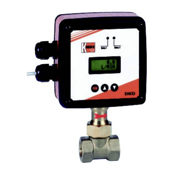
Paddle System Flow
Transmitter for Liquids
Model: DWD
C
A
B
r
i
g
g
s
C
o
m
p
a
n
y
C
A
B
r
i
g
g
s
C
o
m
p
a
n
y
O
r
d
e
r
f
r
o
m
:
O
r
d
e
r
f
r
o
m
:
622 Mary Street; Suite 101; Warminster, PA 18974
Phone: 267-673-8117 - Fax: 267-673-8118
Sales@cabriggs.com
-
www.cabriggs.com
Advertisement
Table of Contents

Subscribe to Our Youtube Channel
Related Manuals for Kobold DWD


Summary of Contents for Kobold DWD
- Page 1 Operating Instructions Paddle System Flow Transmitter for Liquids Model: DWD 622 Mary Street; Suite 101; Warminster, PA 18974 Phone: 267-673-8117 - Fax: 267-673-8118 Sales@cabriggs.com www.cabriggs.com...
-
Page 2: Table Of Contents
9. Technical Information .................. 14 10. Order Codes ....................15 11. Maintenance ....................16 12. Dimensions ....................16 13. Declaration of Conformance ............... 20 Manufactured and sold by: Kobold Messring GmbH Nordring 22-24 D-65719 Hofheim Tel.: +49(0)6192-2990 Fax: +49(0)6192-23398 E-Mail: info.de@kobold.com Internet: www.kobold.com... -
Page 3: Note
• Operating Instructions 4. Regulation Use The Paddle System Flow Transmitter for Liquids, model DWD, is used for monitoring and measuring of liquid flows. Only low viscous and homogenous media may be measured, which do not affect the materials used in the instrument. -
Page 4: Operating Principle
Especially the following points have to be attended: - The provided ferrites have to be mounted as described. - Signal and supply cable of the DWD may not directly taken close to 230 V or 380 V wirings. - The device should not be installed close to inductance, switching loads, engines or similar sources of inductive fields. -
Page 5: Flow Direction
Units with FLANGED CONNECTION Suitable flange sealing is to be used. This, as well as mounting screws, is not included in delivery scope. Take care that the unit does not get damaged during installation. DWD K04/0910 page 5... - Page 6 (groove in the flowing against side). Opposite of the groove is a paddle limiter, which should not be damaged or removed during the mounting procedure. Ca. 23 72.1 OBOLD Relay 1 Relay 2 UM-SW 32 page 6 DWD K04/0910...
-
Page 7: Electrical Connection
If the leads are switched, the fuse must be changed. Attention! A supplied ferrite with a coil must be mounted at the connection cable for magnetic field protection. DWD K04/0910 page 7... -
Page 8: Analogue Output
Interface As special option, the DWD is also available with an interface RS232C. The provided serial cable will be connected to the PC board via a plug. A supplied ferrite with a coil must be mounted at the connection cable for magnetic field protection. -
Page 9: Commissioning
If you keep the buttons on hold, the value changes continuously. After some time, speed increases. At some points of the menu, the DWD informs you which buttons have to be pressed as next step. For example PIN [+/-], whereby + corresponds to button ⇑... -
Page 10: Adjusting Of The Output
The initial of the measuring range of the Paddle System Flow Transmitter for Liquids DWD does not start at zero. At a measuring range of e.g. 10 – 100 L/min, the output is 4 mA between 0 and 9,99 L/min. From 10 L/min the analogue output increases linear from 5,6 mA to 20 mA at 100 L/min. -
Page 11: Adjusting Of Standard Indication Mode
POWER LOW / PRESS P & ⇑ respectively PRESS P & ⇑. After pressing PGM and ⇑ (at same time), the DWD changes back to standard mode. After that, the device starts counting from the amount that was present at the time of power failure. -
Page 12: Restriction Of Access By Code Number
DWD starts with zero again. At the totaliser menu, you see the actual value immediately after switching over to the totaliser function. That means, when the totaliser menu is selected, the indication is always updated. The actual value is only indicated if the totaliser is defined as standard indication. -
Page 13: Protection On Data Loss
This could be: mounting the provided ferrites, installation of the device at another position, changing the cabling within the installation (no measure or feed lines of the transmitter near high voltage feed cable). Reducing of radiation or magnetic field or even the installation of suitable electrostatic shields. DWD K04/0910 page 13... -
Page 14: Technical Information
1 : 10 standard (for example: 10-100 l/min) Accuracy: +/- 1.5 % FS Medium temperature: -20 ... +120 °C (other on request) Max. pressure: 25 bar (DWD-x5.., DWD-x6..) 16 bar (DWD-x7) (other on request) Flow: direction of arrow Mounting position: 4 –... -
Page 15: Order Codes
DWD-15.. DWD-16.. DWD-17.. N50= 2 NPT* *Model DWD-15... female thread to R40, above external thread; Model Typ DWD-16.../DWD-17... female thread to R40, above external thread Paddle System Flow Transmitter for Liquids model DWD-2.. with flange connection Flow range Material combination... -
Page 16: Maintenance
Attention! To separate the instrument from the T-piece, unscrew the union nut and tilt the unit as much as possible to direction of flow. Then lift the DWD with paddle out of the fitting. Please perform all operations with great care to avoid damage especially to the paddle . - Page 17 DWD-15.. from 2” with male thread connection DWD-16.. and DWD-17 from 1” with male thread connection Values in ( ) are valid for DWD-16... Values for DWD-17... on request L (mm) H (mm) 1” 185 (201) 1 1/4” 190 (201) 1 1/2”...
- Page 18 DWD-2.. with flange connection Values in ( ) are valid for DWD-26... Values for DWD-27... on request K (mm) L (mm) DL (mm) H (mm) 185 (201) 190 (201) 194 (201) 202 (211) page 18 DWD K04/0910...
- Page 19 DWD-3.. with weld-on connection Values are valid for DWD-35... and DWD-36... Values for DWD-37... on request H (mm) from DN 40 DWD K04/0910 page 19...
-
Page 20: Declaration Of Conformance
13. Declaration of Conformance We, M/s KOBOLD Messring GmbH, Hofheim-Ts. Germany, declare under our sole responsibility, that this Product: Paddle System Flow Transmitter for Liquids Model: DWD-... which relates to this certificate, conforms to the standards listed below: EN 55011...
Need help?
Do you have a question about the DWD and is the answer not in the manual?
Questions and answers