Table of Contents
Advertisement
Quick Links
Advertisement
Table of Contents

Related Manuals for Kobold PAD


Summary of Contents for Kobold PAD
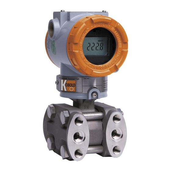
- Page 1 Operating Instructions Smart Pressure Transmitter Model: PAD...
-
Page 2: Table Of Contents
EEProm-Write Enable / Disable Mode Switch ........19 Configuration of Alarm and Security Jumper Procedures ....20 Configuration Using Zero and Span Push Buttons ......20 Additional Functions (valid for PAD-F only) ........31 Wiring Connections for External HHT/ Ammeter ........ 38 5. Installation ....................39 Overview .................... - Page 3 8. Appendix I ....................63 9. Declaration of Conformance ............... 65 10. ATEX Certificate ..................66 Manufactured and sold by: Kobold Messring GmbH Nordring 22-24 D-65719 Hofheim Tel.: +49(0)6192-2990 Fax: +49(0)6192-23398 E-Mail: info.de@kobold.com Internet: www.kobold.com PAD K05/0411 ATEX page 3...
-
Page 4: Introduction
2. Introduction The PAD Smart Pressure Transmitter is correctly calibrated at the factory before shipment. To ensure correct and efficient use of the instrument, please read this manual thoroughly and fully understand how to operate the instrument before operating it (1) The contents of this manual are subject to change without prior notice. -
Page 5: Overview Of Transmitter
& long term stable gauge and absolute pressure measurements over a wide range of operating conditions. PAD is a two wire loop power transmitter and has a standard 4/20mA output scaled for desired output pressure range. In addition it also offers digital HART®... -
Page 6: Transmitter Components
● ● ∆ ● : Supported. ∆ : Supported but update required 2.4 Transmitter Components The various components of PAD Series Smart Pressure Transmitter are shown below: Figure 2-1. Model PAD Transmitter Exposed View (Housing) page 6 PAD K05/0411 ATEX... - Page 7 Figure 2-2. TRANSMITTER COMPONENTS (HOUSING) PAD K05/0411 ATEX page 7...
- Page 8 Figure 2-3. Model PAD Exploded View (Sensor Module-D,G) Figure 2-4. TRANSMITTER COMPONENTS (SENSOR MODULE -D, G) page 8 PAD K05/0411 ATEX...
- Page 9 Figure 2-5. Model PAD Exploded View (Sensor Module-H) Figure 2-6. TRANSMITTER COMPONENTS (SENSOR MODULE -H) PAD K05/0411 ATEX page 9...
-
Page 10: Handling Cautions
(Applying Pressure - Close equalizing valve of 3/5 valve manifold, then, pressure) open stop valve on high and low side slowly and simultaneously. Operation - Make sure that transmitter operates within specs. Visual or HHT page 10 PAD K05/0411 ATEX... -
Page 11: Unpacking
(3) If storing a transmitter that has already been used, thoroughly clean all wetted parts including diaphragm seals (if installed), process connections/manifolds in contact with process fluid. In addition, make sure before storing the transmitter that remote seal (if supplied) assemblies are securely mounted. PAD K05/0411 ATEX page 11... -
Page 12: Selecting The Installation Locations
(5) When using local push buttons please refer to Chapter 4.7 of this manuals for detailed instructions. If using an external HHT or HART® PC configurator please refer to the user manuals supplied by the third party supplier. page 12 PAD K05/0411 ATEX... -
Page 13: Pressure Connections
To test for such effects, bring the transceiver in use slowly from a distance of several meters from the transmitter, and observe the measurement loop for noise effects. Thereafter, always use the transceiver outside the area affected by noise. PAD K05/0411 ATEX page 13... -
Page 14: Insulation Resistance Test And Dielectric Strength Test
ON the power and gradually increase the tester voltage from '0' to the specified voltage. (d) When the specified voltage is reached, hold it for one minute. (e) After completing this test, slowly decrease the voltage to avoid any voltage surges. page 14 PAD K05/0411 ATEX... -
Page 15: Installation Of Explosion Protected Type Transmitters
• Supply Voltage : 11.9…42 V • Output Signal : 4 to 20 mA + HART Note 3. Electrical Connection: see ordering table Note 4. PAD ATEX Certification is according to the below standards EN 60079-0 : 2006 EN 60079-1 : 2004 Note 5. -
Page 16: Emc Conformity Standards
Transmitters to the plant. 4. Transmitter Functions 4.1 Overview This Chapter contains information on operating Model PAD. Tasks that should be performed on the bench prior to installation are explained in this chapter. 4.2 Safety Message Procedures and instructions in this chapter may require special precautions to ensure the safety of the personal performing the operations. -
Page 17: Warning
! Only qualified & trained personnel should be allowed to operate these transmitters. 4.4 Fail Mode Alarm Kobold Smart Pressure Transmitter automatically and continuously performs self- diagnostic routines. If the self-diagnostic routines detect a failure, the transmitter drives its output outside of the normal saturation values. The transmitter will drive its output low (down) or high (up) based on the position of the failure mode alarm jumper . - Page 18 < Fail Mode Selection Jumper Switch of LCD Module > (FAIL MODE DOWN, FAIL MODE SELECT (FAIL MODE UP, place jumper to right) place jumper to left) Figure 4-2 Fail Mode Selection Jumper Switch of LCD Module page 18 PAD K05/0411 ATEX...
-
Page 19: Eeprom-Write Enable / Disable Mode Switch
4.5 EEProm-Write Enable / Disable Mode Switch PAD includes an EEPROM (Electrically Erasable Programmable Read Only Memory) that allows saving and restoring various configuration data within the transmitter on power failure. To lock configuration and protect changes to stored configuration data, one can use a HHC and or external HART® enabled PC device to enable a software lock feature under Status menu. -
Page 20: Configuration Of Alarm And Security Jumper Procedures
(Figure 4-4). You may reconfigure the function settings of ZERO, SPAN, ZERO TRIM, ZERO ADJ, Units, Range, Damping, LCD and Decimal place, using ZERO / SPAN buttons. Zero/Span Button [Figure 4-4 Transmitter Zero/Span configuration Buttons] page 20 PAD K05/0411 ATEX... - Page 21 After 30 seconds inactivity the automatic time out feature will default user back to normal measurement mode with a “BT-Err” message on display. Please refer to Appendix 1 for LCD display messages and the button errors. PAD K05/0411 ATEX page 21...
- Page 22 Damping Second and other requirements of the loop dynamics of your system Change LCD Mode To modify LCD Mode as user desires Decimal Place To modify decimal place as user desires page 22 PAD K05/0411 ATEX...
- Page 23 ZR-“. This message means that the Zero configuration is completed and saved. - If Zero Configuration was incorrectly performed the LCD will display error code “ZR-ERR” indicating failure and possible LRV setting out of sensor range capabilities. Try repeating the Zero configuration steps. PAD K05/0411 ATEX page 23...
- Page 24 “12 Zero Adjustment”, “ 22 Change Upper Range Value”, “23 Change Lower Range Value” and “24 Damping”. When activating these sub-menus (by pushing down & releasing (span) button from within its active menu) the display will automatically prompt for “SEL INC” message. page 24 PAD K05/0411 ATEX...
- Page 25 (Important Note: make sure process input to transmitter is at true zero else this may create an incorrect Zero Offset. If a wrong zero is suspected please execute Zero Trim again ensuring the proper steps & correct Zero PV input is applied to transmitter) PAD K05/0411 ATEX page 25...
- Page 26 Release button when display changes to 211 (xxx) where “ xxx “ are the last units (e.g. bar, kpa, “H2O etc) saved previously. - Press ZERO button repetitively until the desired unit is displayed on the bottom of the LCD. Save and exit by pressing (Span) button. page 26 PAD K05/0411 ATEX...
- Page 27 –DONE- will the transmitter update its stored configuration & accept the new values. If out of limits the transmitter will reject values entered and default to previous saved values after displaying a “RNGOVR” error message. PAD K05/0411 ATEX page 27...
- Page 28 - Press SPAN button until “31 LCD-MD” message appears. Press SPAN button again to access function “LCD Multi-display”. - Press ZERO button repetitively until the desired display form is displayed on the bottom of the LCD (see table below for different options). page 28 PAD K05/0411 ATEX...
- Page 29 As such with engineering mode enabled users can program custom units, engineering units for flow, volume totals and level, scale different URV/LRV, linear mode etc independent of those explained in previous sections. PAD K05/0411 ATEX page 29...
- Page 30 - The LCD will display “LCD_OV” and current setting unit when the pressure exceeds the limit of the setting value. • Please refer to Appendix 1 for LCD display message and the button errors. page 30 PAD K05/0411 ATEX...
-
Page 31: Additional Functions (Valid For Pad-F Only)
By calculated flow rate, Pulse Output with linear, flow rate is created integration value is created. Note: PAD-F measures the flow rate by using differential pressure. It cannot compensate the changes in operating temperature and static pressure. 4.8.2 Pulse Output 4.8.2.1 The appearance and definition of port. - Page 32 When pulse output is used, the most important thing is to check the above Duty_cycle, Flow_rate and Pulse_scale. The specification check of the system in which PAD-F pulse output will be input is also important. For examples, if the system to which PAD-F will be applied is used to measure the flow rate 0~20,000l/h and the Pulse_Scale is set to 0.1, Pulse Duty Cycle will be shown as...
- Page 33 On the above result, the value exceeds the maximum Duty cycle (49Pulse/sec) PAD-F can output. In this case, Pulse_Scale must be set to 1 or more. If the system requires Pulse_Scale to be set to 0.1 or less, you can not use PAD-F. On the contrary, in case of the system that Duty_cycle is primarily decided, you need to calculate the Flow_rate and check it matches the value of system design.
- Page 34 Remark on LCD Shows Flow Rate/ Totaliser/ PV FL_RO Flow Rotation Mode values in rotation on LCD F_RATE Flow Rate Shows Flow Rate value on LCD FTOTAL Flow Totaliser Shows Flow Totaliser value on LCD page 34 PAD K05/0411 ATEX...
- Page 35 “xxx” where “xxx“ are the last flow units saved previously. - Press ZERO button repetitively until the desired Flow Rate Unit is displayed on the bottom of the LCD. - Save and exit by pressing (Span) button. PAD K05/0411 ATEX page 35...
- Page 36 - Press SPAN button to access function “Change Lower Range Value”. - Follow Set numeric value procedure explained in section 4.7.3.3 to input desired Flow Rate LRV numeric value equivalent to 0% of pressure (4mA). page 36 PAD K05/0411 ATEX...
- Page 37 - Push (Zero) button to move down one sub menu and release button when “45 PSCALE” message is displayed. - Push (Zero) button to move down one sub menu and release button when “46 PWIDTH” message is displayed. PAD K05/0411 ATEX page 37...
-
Page 38: Wiring Connections For External Hht/ Ammeter
SPAN to save and exit. 4.9 Wiring Connections for External HHT/ Ammeter PAD Pressure Transmitter can also be commissioned using a HART® enable HHT Or PC configurator either before or after installation. A complete commissioning consists of configuring and/ or verifying transmitter configuration data, testing the transmitter, testing the loop and zero trimming. -
Page 39: Installation
5. Installation 5.1 Overview The information in this chapter 5 covers installation considerations. Dimensional drawings for Model PAD variation and mounting configuration are included in this chapter. 5.2 Safety Message Procedures and instructions in this chapter may require special precautions ensure the safety of the personnel performing the operation. -
Page 40: Warning
! If the process fluid may be toxic or otherwise harmful, take appropriate care to avoid contact and/ or exposure to direct vapours even after dismounting the instrument from process line for maintenance. page 40 PAD K05/0411 ATEX... -
Page 41: Commissioning On The Bench With Hand-Held Terminal
Verify using calibrated Pressure Support Do you satisfy Maintenance Spec? Field Install a) select correct location b) connect signal leads c) check grounding d) connect power supply e) Verify values [Figure 5-1 Commissioning Flow Chart] PAD K05/0411 ATEX page 41... -
Page 42: General Considerations
5.5 General Considerations The PAD transmitter uses a capacitance or piezoresistive pick up. As changes in pressure are accurately detected, any zero shift or installation offsets will be transmitted as a pressure change on the 4~20mA analogue current output. Hence it is recommended that the transmitter be mounted as close to the process as possible and use short impulse piping, when possible, to achieve best accuracy. -
Page 43: Wiring
(4) Avoid running signal wiring near AC or high power lines. In case of ground signal, ground the signal loop's on one side making sure other side is not grounded. (5) Ensure loose contacts are eliminated and proper wiring connections are maintained. PAD K05/0411 ATEX page 43... - Page 44 Figure 5-2 below for wiring instructions. C O M M C O M M TEST TEST Figure 5-2 Connection with Terminal Board of Transmitter Local Indicator Ampere Meter DCS or Power Supply Figure 5-3 Picture of Terminal Board of Transmitter page 44 PAD K05/0411 ATEX...
- Page 45 5.7.4 Wiring A. Loop Configuration Kobold Series Transmitters use a two-wire system for power supply, 4~20mA analogue signal transmission and HART digital transmission. DC Power Supply is required for the transmitter loop. The Transmitter and distributor are connected as shown below.
- Page 46 • A seal fitting must be installed near the terminal box connections port for a sealed construction. • Apply a non-hardening sealant to the threads of the terminal box connection box, flexible metal conduit and deal fitting for waterproofing. [Figure 5-4b Typical Wiring using Flameproof Metal Conduit] page 46 PAD K05/0411 ATEX...
- Page 47 • General Standard : 11.9 to 45 V • Hart Communication : 17.4 to 45 V And maximum loop current is 24mA, Load resistance R: R = (E-11.9) / 0.022 (E = Power Supply Voltage) PAD K05/0411 ATEX page 47...
- Page 48 [Note] In case of an intrinsically safe transmitter, external load resistance includes safety barrier resistance. page 48 PAD K05/0411 ATEX...
-
Page 49: Mechanical Considerations
5.8 Mechanical Considerations Figure 5-6 is transmitter dimensional drawings of PAD. A mounting example and dimensional drawings are shown in Figure 5-7. Figure 5-6. Model PAD Outline Dimension Drawing PAD K05/0411 ATEX page 49... - Page 50 Vertical Mounting Type 2“ Pipe Mounting Bracket Model: ZUB-PAD/PAS-K Horizontal Mounting Type 2“ Pipe Mounting Bracket Model: ZUB-PAD/PAS-L Figure 5-7. Typical Bracket Mounting page 50 PAD K05/0411 ATEX...
-
Page 51: Environmental Considerations
5.9.2 Toxic/ High Humidity considerations Housing of PAD Smart transmitters is protected from direct exposure to moisture or toxic materials provided front and rear covers are engaged fully with appropriate O-rings included. Electronic circuits are separated from terminal side;... -
Page 52: On-Line Operation
6. On-line Operation 6.1 Overview This chapter describes configuration functions of PAD smart pressure Transmitter. Transmitter can be configured in either On-Line or Off-Line mode. In On-Line configuration mode, you must connect through an external HHT (Hand ® Held Terminal) supporting HART DDL technologies. -
Page 53: Check Output
8, 12, 16, 20 mA for testing current outputs. 6.4.1 Process Variable The PAD Smart pressure transmitter measures two variables. Primary Variable is always the process pressure measured and SV (Secondary Variable) is the temperature. Note: Temperature measured is used strictly for internal compensation . -
Page 54: Detailed Setup
8 alpha-numeric characters. For additional description use Set Message option under 6.7.2. 6.7.2 Set Messages When using several transmitter, user may classify each transmitter by using 32 alpha-numeric characters. This message is saved in EEPROM of transmitter. page 54 PAD K05/0411 ATEX... -
Page 55: Diagnostics And Services
It is highly recommended to perform a sensor trim when first commissioning the transmitter on site. There are three ways to trim the sensor: Sensor zero trim, full trim and zero adjustment. PAD K05/0411 ATEX page 55... -
Page 56: Advance Set Up
Output Mode The transmitters can be set to output its 4/20 mA signal in linear or Square Root. Square Root mode may be desirable configuration when installing a PAD-D or PAD-F for flow measurement. In Engineering mode (when enabled) users have added flexibility of enabling square root mode only for local display purpose on LCD and retain a linear 4/20 mA current output for a remote totaliser or DCS /PLC control system. -
Page 57: Maintenance
! f the process fluid may be toxic or otherwise harmful, take appropriate care to avoid contact and/ or exposure to direct vapours even after dismounting the instrument from process line for maintenance. PAD K05/0411 ATEX page 57... -
Page 58: Hardware Diagnostics
Loop Wiring Output multiple grounds. Check polarity of signal terminal " " Check the loop impedance. " Connect HHT and check the sensor limits to Electronics ensure calibration adjustments are within the Module sensor range. page 58 PAD K05/0411 ATEX... -
Page 59: Hardware Maintenance
7.4 Hardware Maintenance Kobold PAD Smart Transmitters have no moving parts and require a minimum of scheduled maintenance. Both transmitters feature modular design for easy maintenance. If you suspect a malfunction, check for an external cause before performing the diagnostics as discussed later in this section. If you must return failed transmitters or parts, send them to Kobold Messring GmbH for inspection, repair, or replacement. - Page 60 5. Remove the analogue sensor cable & power cables from their plug in connectors. 6. Firmly grasp the electronics module and pull it straight out of the housing, taking care not to damage the interconnecting pins. page 60 PAD K05/0411 ATEX...
- Page 61 Switches settings on the replacement board. Figure 7.3 Structure of Electronics Module inner Transmitter 7.4.2.2 Fail Mode and Jumper Switch of EEPROM-write Fail-mode and jumper switch of EEPROM-write are located front of electronics module (Refer to Figure 4-3) PAD K05/0411 ATEX page 61...
- Page 62 8. If all self checks are completed and found OK, the transmitter will enter measurement mode automatically. 9. If any errors are found, same will be displayed on LCD. Follow the troubleshooting guide included in this manual to help identify and correct any fault conditions. page 62 PAD K05/0411 ATEX...
- Page 63 8. Appendix I PAD SMART PRESSURE TRANSMITTER LCD DISPLAY CODE Message Description Remarks ADJ-U Out of Zero setting value when Zero Adj function using button(Upper side) ADJ-L Out of Zero setting value when Zero Adj function using button(Lower side) ZERO...
- Page 64 Indicating 4 ~ 20 mA value depending on measured PV NOR_mA value on LCD Indicating the value with Engineering PV, Engineering %, ENG_RO Engineering mA units as continually on LCD Indicating changed PV value with modified Engineering ENG_PV range page 64 PAD K05/0411 ATEX...
-
Page 65: Declaration Of Conformance
EN 55011 EMS (Immunity): EN 50082-2 Kobold Messring GmbH recommends customer to apply the Metal Conduit Wiring or to upset he twisted pair Shield Cable for signal wiring to conform the requirement of EMC Regulation, when customer installs Kobold Series Transmitters to the plant.
Need help?
Do you have a question about the PAD and is the answer not in the manual?
Questions and answers