Table of Contents
Advertisement
Quick Links
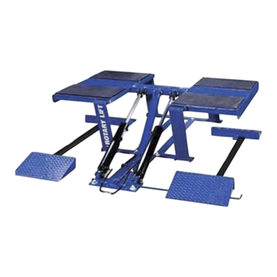
Low Rise Car Lift
(Maximum 1750 lbs. per pad)
© August 2007 by Rotary Lift. All rights reserved. CO6380.3
VLXS7
Capacity 7000 lbs.
VLXS10
Low Rise Car Lift
Capacity 10,000 lbs.
(Maximum 2500 lbs. per pad)
LP20389
I
I
N
N
S
S
T
T
A
A
L
L
L
L
A
A
T
T
I
I
O
O
N
N
I
I
N
N
S
S
T
T
R
R
U
U
C
C
T
T
I
I
O
O
N
N
S
S
IN20389
Rev. C 08/13/2007
Advertisement
Table of Contents

Related Manuals for Rotary VLXS7


Summary of Contents for Rotary VLXS7
- Page 1 VLXS10 Low Rise Car Lift Low Rise Car Lift Capacity 7000 lbs. Capacity 10,000 lbs. (Maximum 1750 lbs. per pad) (Maximum 2500 lbs. per pad) LP20389 IN20389 © August 2007 by Rotary Lift. All rights reserved. CO6380.3 Rev. C 08/13/2007...
- Page 2 VLXS10 VLXS7 Fig. 1 CLEARANCE AROUND VLXS10 LIFT CLEARANCE AROUND VLXS7 LIFT A. Overall Length ..........7'-7" (2311mm) A. Overall Length ..........7'-7" (2311mm) B. Overall Width..........6'-11-3/4" (2127mm) B. Overall Width..........6'-11-3/4" (2127mm) C. Minimum To Center Of Next Lift ....11'-0" (3353mm) C.
- Page 3 3. Anchoring: IMPORTANT If an anchor will not reach the appropriate A. The anchor bolts must be installed at least 5-11/16” (145mm) torque level or does not have enough embedment or adequate from any edge or seam in the concrete spacing cannot be achieved, replace the concrete under the B.
- Page 4 4. Install Power Unit And Mounting Post: Single Phase Rotary Power Unit A. Refer to architect’s plan for placement of power unit mounting Motor Operating Data - Single Phase post. Using the stand as a template mark location of (4) floor anchor holes.
- Page 5 Rear Approach Front Approach Front Approach Hose Routing Hose Routing Hose Routing (With Conduit) (With Conduit) (With Hose Guard) Fig. 6 6. Running Hoses And Bleeding The Hydraulic System: Connect 90 degree JIC elbow to swivel tee and then long hose to male adapter.
- Page 6 B. Drill (4) 1/4" anchor holes and install anchors. RAMP CLEARANCE TABLE 1/2" (13mm) minimum clearance. 5/8" (16mm) minimum clearance. Anchor hole locations for wheel dish. Fig. 8 16" 16" (406mm) (406mm) 9-1/2" 9-1/2" (241mm) (241mm) 9-1/2" 9-1/2" (241mm) (241mm) VLXS10 VLXS7 7" 7" (178mm) (178mm) Fig. 7...
- Page 7 11. Final Adjustments: A. Install and tighten the remaining two anchors as described in Fig. 4. B. If any problems are encountered, do not proceed with subsequent steps. Instead, resolve the problem before proceeding by referencing the Troubleshooting portion of the Owner’s Manual section of this manual.
- Page 8 Australasia: +60.3.7660.0285 e userlink@rotarylift.com Latin America / Caribbean: +54.3488.431.608 ® © Rotary , Printed in U.S.A., All Rights Middle East / Africa: 1.812.273.1622 Reserved. Unless otherwise indicated, ROTARY, DOVER and all other trademarks are property of Dover Corporation and its affiliates.
Need help?
Do you have a question about the VLXS7 and is the answer not in the manual?
Questions and answers