Table of Contents
Advertisement
Quick Links
Rotary Parallelogram
SAFETY INSTRUCTIONS .............................................................3
COMPONENT IDENTIFICATION & INSTALL OPTIONS ...........4
SYSTEM OPERATIONS ................................................................7
INSPECTION AND MAINTENANCE ............................................9
TROUBLE SHOOTING ................................................................13
LIFT LOCKOUT/TAGOUT PROCEDURE ..................................20
OPERATING CONDITIONS ........................................................20
© January 2017 by Vehicle Service Group. All rights reserved.
Lift Systems
Generation 5 Flush & Surface Lifts
Table of Contents
CO10004
O
O
P
P
E
E
R
R
A
A
T
T
I
I
O
O
N
N
&
&
M
M
A
A
I
I
N
N
T
T
E
E
N
N
A
A
N
N
C
C
E
E
M
M
A
A
N
N
U
U
A
A
L
L
OM20187
Rev. G 1/16/2017
Advertisement
Table of Contents

Related Manuals for Rotary 30/26-F


Summary of Contents for Rotary 30/26-F
-
Page 1: Table Of Contents
Rotary Parallelogram Lift Systems Generation 5 Flush & Surface Lifts & & Table of Contents SAFETY INSTRUCTIONS .............3 COMPONENT IDENTIFICATION & INSTALL OPTIONS ...4 SYSTEM OPERATIONS ..............7 INSPECTION AND MAINTENANCE ..........9 TROUBLE SHOOTING ..............13 LIFT LOCKOUT/TAGOUT PROCEDURE ........20 OPERATING CONDITIONS ............20 OM20187 ©... -
Page 2: Owner/Employer Responsibilities
OWNER/EMPLOYER RESPONSIBILITIES The Owner/Employer: • Shall ensure that lift operators are qualified and that they are trained in the safe use and operation of the lift using the manufacturer’s operating instructions; ALI/SM07-1, ALI Lifting it Right safety manual; ALI/ST-05 ALI Safety Tips card; ANSI/ALI ALOIM-2008, American National Standard for Automotive Lifts-Safety Requirements for Operation, Inspection and Maintenance;... -
Page 3: Safety Instructions
The Rotary or major fluid leak. Parallelogram is unique from other above-ground lifts because it has no posts and has a clear floor design. -
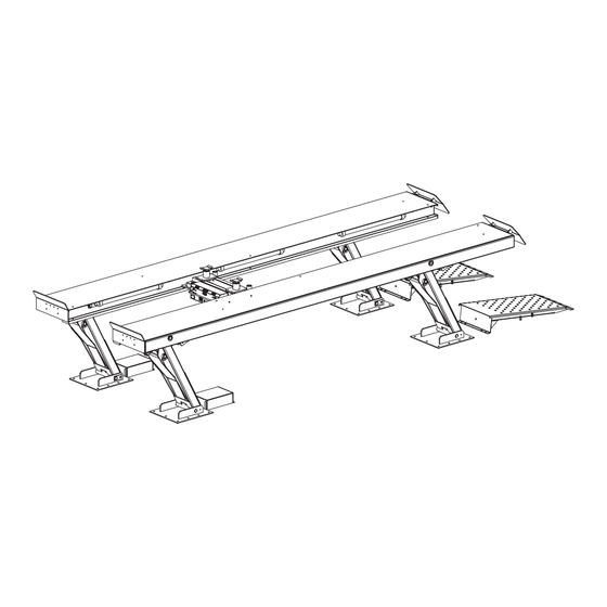
Page 4: Surface Mount
Lift Component Identification Install Options SURFACE MOUNT OPTIONAL TRANSITION PLATE & AXLE JACK WHEEL STOP PLATFORM OPTIONAL FLOURESCENT LIGHTS WHEEL STOP SAFETY STOP DRIVE ON RAMPS (3) PIN CONNECTIONS PER LEG HYDRUALIC CYLINDER, POSITION SENSOR, & LOWER LEG MECHANICAL SAFETY BRACKET LOCKS LEG MEMBER... - Page 5 Lift Component Identification Install Options FLUSH MOUNTED SIDE VIEW For Models: 30/26-F 36/28-F 50/26-F 50/28-F For Models: 45/35-F 50/32-F 50/48-F 75/30-F For Models: 100/42-F 75/48-F Fig. 3 SURFACE MOUNTED SIDE VIEW For Models: 25/26-S 30/26-S 36/28-S 50/26-S 50/28-S For Models:...
- Page 6 Lift Component Identification Install Options Side Elevation - Normal FRONT REAR Installation Lift Fully Raised Side Elevation - Custom FRONT REAR Installation Lift Fully Raised Side Elevation - Custom FRONT REAR Installation Lift Fully Raised Note: For consistency legs always point toward the front of the lift. Fig.
-
Page 7: System Operations
System Operations • RESETTING AN OPERATOR LOCKOUT- Reset the OPERATOR CONTROL PANEL control panel by sequencing a RESET of the control The primary operator controls are located on the panel. This is initiated by depressing all three push- top surface of the control panel, see Figure 6. Inside buttons simultaneously. -
Page 8: Summary Of Operation
System Operations SUMMARY OF OPERATION push-button to initiate the engagement of the mechanical locks. The lift will then lower onto the mechanical lock • RAISING THE LIFT: Pressing the RAISE push- stops. The lift is now mechanically secure (metal on button (green) starts the hydraulic oil pump which metal). -
Page 9: Inspection And Maintenance
Inspection and Maintenance All Rotary Parallelogram Lift Systems models have The safety control system is designed to sense been designed for safety and dependability. This is the the condition where a lock jaw remains stuck in finest lift available on the market today. It is designed to the open position. - Page 10 Inspection and Maintenance C.) HYDRAULIC SYSTEM INSPECTION: The hydraulic system including the hoses and fittings must be inspected every six months. To perform the hydraulic inspection raise the lift and press the PRESS-TO-LOCK push button on the control panel. Go to each leg and inspect the condition of the cylinders and hydraulic lines leading to the cylinder. The condition of the hoses must be inspected carefully.
-
Page 11: Periodic Maintenance
Any findings of the inspection (normal or abnormal) not add or check oil in any position other than fully should be recorded. This information is helpful to Rotary lowered; the level would not be accurate and oil Lift in identifying and correcting any generic problems could overflow the reservoir if oil was added. - Page 12 Inspection and Maintenance Periodically check for any dirt or contaminants in the oil reservoir - contaminants (dirt or grit) could damage the seals of the hydraulic cylinder resulting in a potentially serious safety hazard. When Contaminants are Found: 1.) Remove contaminants/oil at once. 2.) Thoroughly clean the reservoir.
-
Page 13: Troubleshooting
Troubleshooting Operator Lockout Troubleshooting Chart DESCRIPTION OF FAULT SOLUTIONS/SUGGESTIONS # OF FLASHES LOW AIR • Air supply not functioning • Broken Air Lines • Loose or Damaged wiring to air switch inside control cabinet SAFETY RAIL ON PLATFORM • Check for obstruction and reset at control panel HAS BEEN TRIPPED •... - Page 14 Rotary Lift at 1-800- out the control system; however, with the aid of the 445-5438.
- Page 15 Troubleshooting MANUAL PUMP PROCEDURE Lift out of Alignment- This procedure is used when the Operator Lockout light is indicating 4 flashes. What to Do: • Attempt to reset the control panel by sequencing a RESET of the control panel (i.e., depressing all three push buttons simultaneously).
- Page 16 Troubleshooting MANUAL PUMP PROCEDURE #1: There are three completely different procedures performed using the manual pump procedure. Carefully Platforms are out of level for the following determine which procedure fits your particular situation. reasons: The procedures are listed below: • Obstructions of a retraction lifting leg.
- Page 17 Troubleshooting MANUAL PUMP PROCEDURE #2: Procedure #1 Steps to follow: Platforms are out of level for the following reasons: 3. (continued) Remove all tools and check to make • One side of the lift has been loaded beyond rated sure all needle valves are secured. Replace the capacity.
- Page 18 Troubleshooting MANUAL PUMP PROCEDURE #3: Procedure #2 Steps to follow: Platforms are out of level for the following 4. (continued) Loosen the locknut surrounding reasons: the needle valve stem.. Turn the needle • The building voltage supply (single phase, 3 valve with an Allen wrench approximately phase or both) is not present at the control one-quarter turn counter clockwise.
- Page 19 Troubleshooting 4. (continued) Locate the handle used for the manual Manually lowering the lift will go CAUTION pump and place it in the pump socket. Activate slowly. Release the manual operator control the manual operator that will send air to actuate on the pneumatic valve - This will engage the air cylinders on the mechanical safety locks.
-
Page 20: Lift Lockout/Tagout Procedure
The responsibility for assuring that this procedure is followed is binding upon all employees and service personnel from outside service companies (i.e., Authorized Rotary Installers, contactors, etc.). All employees shall be instructed in the safety significance of the lockout procedure by the facility owner/manager. - Page 21 NOTES...
- Page 22 NOTES...
- Page 23 NOTES...
Need help?
Do you have a question about the 30/26-F and is the answer not in the manual?
Questions and answers