Sign In
Upload
Download
Table of Contents
Contents
Add to my manuals
Delete from my manuals
Share
URL of this page:
HTML Link:
Bookmark this page
Add
Manual will be automatically added to "My Manuals"
Print this page
×
Bookmark added
×
Added to my manuals
Manuals
Brands
Rotary Manuals
Lifting Systems
AR43-5MB
Operating and maintenance manual
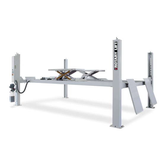
Rotary AR43-5MB Operating And Maintenance Manual
4-post lift
Hide thumbs
1
2
3
4
Table Of Contents
5
6
7
8
9
10
11
12
13
14
15
16
17
18
19
20
21
22
23
24
25
26
27
28
29
30
31
32
33
34
35
36
37
38
39
40
41
42
43
44
45
46
47
48
49
50
51
52
53
54
55
56
57
58
59
60
61
62
63
64
page
of
64
Go
/
64
Contents
Table of Contents
Troubleshooting
Bookmarks
Table of Contents
Table of Contents
1 Introduction
About this Operating Manual
Warning and Information Symbols
Intended Use
Incorrect Use, Incorrect Behavior
Internal Accident, Health and Safety, and Environmental Information
2 Safety
Operators
Basic Safety Requirements
Permitted Axle Loads and Weight Distribution
Ban on Unauthorized Modifications or Alterations
Experts, Competent Persons
Maintenance Contractors, Installation Staff
Safety Inspections by Competent Persons
3 The 4-Post Lift
Overview of Parts
General Workflow
Work Area, Danger Zones
Safety Mechanisms
Control Unit
4 Operation
Emergency Stop
Switch the Machine on
Determine the Vehicle Data
Driving on
Lifting/Lowering
Drive off
Switch the Machine off
5 Problems, Causes, Actions
Troubleshooting by the Operator
Troubleshooting by Authorized Maintenance Contractors
6 Authorized Lowering
Manually Lowering the Lift When There Is a Height Difference of > 50 MM
Leveling the Rolling Jacks
Emergency Manual Function
7 Technical Data
8 Cleaning
9 Maintenance and Repair
Qualification of Maintenance and Repair Staff
Maintenance and Repair Safety Regulations
Maintenance Work
Approved Hydraulic Oils
Check, Refill, Change the Hydraulic Oil
Repair Work (Repairs)
10 Transport, Storage
Transport
Offloading
Storage
11 Assembly
Assembly Safety Instructions
Quick Assembly Instructions
Site Specifications
Installation Preparations
Prepare the Runways
Prepare the Cross Beams
Set up the Cables
Fasten the Runways to the Cross Beams41
Insert the Latch Bars
Assemble the Lift Column
Attach the Latch Bars and Cables
Attach the Flexible Hose
Assemble the Hydraulics Module
12 Electrical Connections
Safety Instructions for Connecting Power Cables
Connect the Lift Power Supply
13 Commissioning
Test the Pneumatic and Hydraulic System
Test the Safety Mechanism
Align the Rolling Jacks
Leveling the Main Lift
14 Wheel Alignment Kit AK
Supplied Parts
Assembly
Adjustment Work
15 Disassembly
16 Disposal
Environmental Procedures for Disposal55
Packaging
Oils, Grease, and Other Chemical Substances
Metals / Electronic Waste
Advertisement
Quick Links
1
Lifting/Lowering
2
Technical Data
3
Assembly Safety Instructions
Download this manual
SM40, SM40-47BMW,SM40LT,
© Rotary Lift, 03/2013
4-Post Lift
AR43-5MB,
SM55-M51VAS, SM60
CO6941.3
LP20100
OM20121 Rev.D 03/2013
O
P
E
R
A
T
I
N
G
A
N
D
M
A
I
N
T
E
N
A
N
C
E
M
A
N
U
A
L
Table of
Contents
Previous
Page
Next
Page
1
2
3
4
5
Advertisement
Table of Contents
Troubleshooting
Problems, causes, actions
22
Troubleshooting by authorized maintenance contractors
24
Need help?
Do you have a question about the AR43-5MB and is the answer not in the manual?
Ask a question
Questions and answers
Related Manuals for Rotary AR43-5MB
Lifting Systems Rotary SM40-47 Operaton & Maintenance Manual
4 -post alignment lift (66 pages)
Scissor Lifts Rotary SM40 Operation & Maintenance Manual
(45 pages)
Lifting Systems Rotary SM40 Operation & Maintenance Manual
Four post surface lift (12 pages)
Lifting Systems Rotary 100 Series Operation And Maintenance Manual
Four post surface mounted lift (36 pages)
Lifting Systems Rotary 100 Series Installation Instructions Manual
Four post surface mounted lift (60 pages)
Lifting Systems Rotary AR14 Manual
(36 pages)
Lifting Systems Rotary AR40 Operation & Maintenance Manual
Four post surface lift (12 pages)
Lifting Systems Rotary AR55 Operation & Maintenance Manual
Four post surface lift (12 pages)
Lifting Systems Rotary SPOA7 Installation Instruction
(16 pages)
Lifting Systems Rotary SPOA10NB Operation And Maintenance Manual
(8 pages)
Lifting Systems Rotary SPOA7 Operation & Maintenance Manual
With movable pads, capacity 7,000 lbs. (12 pages)
Lifting Systems Rotary SL235MP Installation Instructions Manual
(30 pages)
Lifting Systems Rotary SPM40 Operation & Maintenance Manual
2 post lift (62 pages)
Lifting Systems Rotary 600 Series Operation & Maintenance Manual
Two post surface mounted lifts (16 pages)
Lifting Systems Rotary SPOA10NB Series Installation Instructions Manual
(60 pages)
Lifting Systems Rotary SPO12 Standard Installation Instructions Manual
(72 pages)
This manual is also suitable for:
Sm40lt
Sm40-47bmw
Sm40
Sm55-m51vas
Sm60
Table of Contents
Print
Rename the bookmark
Delete bookmark?
Delete from my manuals?
Login
Sign In
OR
Sign in with Facebook
Sign in with Google
Upload manual
Upload from disk
Upload from URL


Need help?
Do you have a question about the AR43-5MB and is the answer not in the manual?
Questions and answers