Table of Contents
Advertisement
Quick Links
Advertisement
Table of Contents

Related Manuals for Kathrein UFS 641si


Summary of Contents for Kathrein UFS 641si
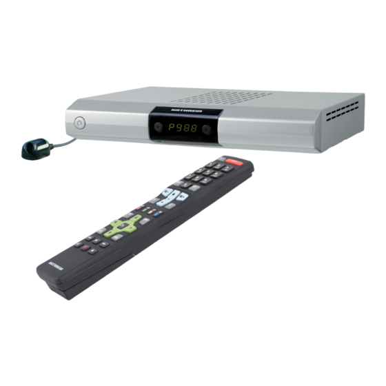
- Page 1 Operating Manual DVB Satellite Receiver UFS 641si...
-
Page 2: Preface
For shorter breaks, you can use the remote control to switch the receiver to standby, which uses only a minimal amount of energy. We wish you good reception and much pleasure using your new DVB satellite receiver. Your KATHREIN team... -
Page 3: Important Information
This unit makes use of legally protected technologies, which are protected by patents in the USA and also by other intellectual property rights in other countries. KATHREIN-Werke KG has obtained licences from Audio MPEG Inc. and Societa‘ Italiana per lo sviluppo dell‘elettronica, S.I.SV.EL, S.P.A to use these technologies. -
Page 4: Table Of Contents
CONTENTS ..........................2 PREFACE ...................... 3 IMPORTANT INFORMATION ..........................4 CONTENTS ................ 6 SAFETY INSTRUCTIONS - IMPORTANT NOTES ................8 RECEIVER FEATURES/SCOPE OF SUPPLY ................9 CONTROLS, DISPLAYS AND CONNECTIONS ..................... 10 CONNECTION AND SETUP ....................12 SUSPENDED INSTALLATION ................12 INSTALLATION ON A FIXED FLAT SURFACE ........................ - Page 5 CONTENTS ......................... 48 SKIP CHANNELS ........................ 49 LOCK CHANNELS ................49 COPY CHANNELS TO THE FAVOURITES LIST ............49 START BLOCKSELECTION (MARKING SEVERAL CHANNELS) ...................... 50 EDIT FAVOURITES LISTS ..................50 REMOVE FROM FAVOURITES LIST ........................ 51 LOCK CHANNELS ....................... 51 RENAME FAVORITELIST ............
-
Page 6: Safety Instructions - Important Notes
SAFETY INSTRUCTIONS - IMPORTANT NOTES These two pages contain important information about operation, installation location and connection of the unit. Read these instructions carefully before setting up the device. Mains cable Moisture, direct sunlight, heat, naked fl ames Make sure that the mains cable Protect the unit against moisture, (power supply cable) is not damaged. - Page 7 SAFETY INSTRUCTIONS - IMPORTANT NOTES Do not place any objects on top of Installation location the unit. Unless stated to the contrary All electronic equipment generates in the “Connection and Setup” and heat. temperature rise “Installation” sections in the manual this unit does however lie within included, maintain...
-
Page 8: Receiver Features/Scope Of Supply
RECEIVER FEATURES/SCOPE OF SUPPLY The UFS 641si receiver is suitable for the reception of digital satellite TV and radio channels. The HDMI interface offers the optimum capability for connecting the receiver to a fl at-screen TV set. The built-in up-scaler processes the picture optimally for fl at-screen TV sets. -
Page 9: Controls, Displays And Connections
CONTROLS, DISPLAYS AND CONNECTIONS This section provides a brief description of all the controls, displays and connections. VIEW OF FRONT PANEL (FLAP REMOVED)/REAR PANEL On/Off switch Video output (composite colour) Channel selection (P-) Digital data stream output (S/PDIF = Sony/ Philips Digital Interface Format) for Dolby 4-character display Digital AC 3 audio... -
Page 10: Connection And Setup
CONNECTION AND SETUP The following section is intended specifi cally for specialist dealers. You need not refer to this section unless you are carrying out the installation yourself. The “Connection examples” section provides a sample confi guration. Do not connect the receiver to the power supply until all installation work has been properly carried out. Refer to the information in the “Safety Instructions”... - Page 11 + and – markings are indicated inside the battery compartment. Slide the cover back into the housing until it locks in place. INSTALLING THE UFS 641si USING THE MOUNTING SUPPORT The mounting support supplied offers you the option not only of placing the receiver on a solid fl at surface, but also of mounting it suspended (e.g.
-
Page 12: Suspended Installation
CONNECTION AND SETUP SUSPENDED INSTALLATION Remove the wood screws supplied from their transport attachment on the top of the respective mounting piece (2 pieces). Place the two mounting pieces on your receiver as shown in Figures 1-3. During the process the following should be taken into account: Left (L) and Right (R) markings (see ↓... -
Page 13: Remote Control
REMOTE CONTROL Numeric entry for Power on/stand-by channels, timers etc. Teletext Open the main menu, leave the menu and return to the TV picture Open channel OSD/info Volume Channel selection Sound on/off up/down ... -
Page 14: First Installation
FIRST INSTALLATION: General Before using your receiver for the fi rst time, read the “Safety Instructions” and “Connection and Setup” sections. The “Connection examples” section provides a sample confi guration. Do not connect the receiver to the power supply until all installation work has been properly carried out. - Page 15 FIRST INSTALLATION: General The following on-screen display appears: Use the buttons here to select whether you want to use the pre-programmed channel list (select “No”) or generate a new channel list by searching (select “Yes” - you will be asked later in the ...
- Page 16 FIRST INSTALLATION: General Picture format Here you can select the type of screen display, depending on the setting of your TV aspect ratio: TV aspect ratio “4:3”: Pan & Scan or Letterbox TV aspect ratio “16:9”: “automatically” or “always 16:9” TV-SCART-Output Select the type of video signal at the TV Scart socket here.
- Page 17 FIRST INSTALLATION: DiSEqC™1.0 When selecting the satellite(s), make sure that your reception position aligned desired satellite(s)! Use the buttons here to switch to the “Number of Satellites” selection. Number of Satellites Press the button to select the number of satellites to be received. You can select a number from one to four satellites to be received.
- Page 18 FIRST INSTALLATION: DiSEqC™1.0 The following on-screen display appears (example): Satellite Use the buttons to set the desired satellite (selection from 17 pre-programmed options). LNB Type Here use the buttons to select the LNB type used in your system. The choice is between “Universal”...
- Page 19 FIRST INSTALLATION: LNB only Satellite Use the buttons to select the desired satellite whose signal is to be received by the tuner. When you have selected your desired satellite, buttons to switch to the selection of the “LNB Type”. LNB Type ...
- Page 20 If in your reception system you use a single-cable LNB (e.g. UAS 481 from Kathrein), please select here the setting “Wideband”. If you use a single-cable matrix (EXU 908) or a single- cable switching matrix (EXR 551 or EXR 552) from Kathrein, the LNB you use must be a “Universal LNB”!
- Page 21 FIRST INSTALLATION: One Cable System Universal: No further entry is required, since all necessary frequency ranges are covered by a universal LNB. Wideband: No further entry is necessary, since all frequency ranges are set by the wideband LNB. Single: If you are not using a universal or a wideband system, you must set the frequencies here. You can fi nd the necessary information in the documentation supplied with your system.
- Page 22 KATHREIN EXR 552 (single-cable switching matrix, max. four receivers) KATHREIN EXU 908 (single-cable matrix, max. eight receivers) EXR 4 subscriber (for future Kathrein single-cable (switching) matrices, max. four receivers) EXR 8 subscriber (for future Kathrein single-cable (switching) matrices, max. eight receivers) Selection “user-defi...
- Page 23 FIRST INSTALLATION: One Cable System Test connection When you have completed all the settings, press the buttons to switch to the “Test connection” selection fi eld and press the button. The receiver now tests whether a connection to the single- cable system can be established or not.
- Page 24 FIRST INSTALLATION: One Cable System Selection “UAS 481” or “EXR 551” When the UAS 481 single-cable feed system is being used, it is essential that the LNB is set to “Wideband”! When the EXR 551 single-cable switching matrix is being used, it is essential that the LNB is set to “Universal”! Transmission channel...
- Page 25 FIRST INSTALLATION: One Cable System Selection “EXR 552” When the “EXR 552” single-cable switching matrix is being used, it is essential that the LNB is set to “Universal”! Transmission channel Use the buttons to select a free available transmission channel. A maximum of two transmission channels are available (1400 and 1516 MHz).
- Page 26 FIRST INSTALLATION: One Cable System Selection “EXU 908” When “EXU 908” single- cable matrix is being used, it is essential that the LNB is set to “Universal”! Transmission channel Use the buttons to select a free available transmission channel. A maximum of eight transmission channels are available (1284, 1400, 1516, 1632, 1748, 1864, 1980 and 2096 MHz).
- Page 27 FIRST INSTALLATION: Channel Search Execute channel search Use the buttons to select (Yes or No) whether you want to start a channel search. It is not essential to start a channel search; instead you can use the factory pre-programmed channels. However the channels do change from time to time (e.g.
- Page 28 FIRST INSTALLATION: Channel Search/Date and Time Use the button to move to the next step of the fi rst installation. The following on-screen display appears: Local time offset Use the buttons to set the local time offset from UTC (formerly GMT) (e.g. for Germany +1 hour). ...
- Page 29 FIRST INSTALLATION: SOFTWARE UPDATE On completion of a successful fi rst installation (TV picture can be seen) we recommend having the receiver search for any available software update. It is a prerequisite that you have selected (included in the selection) the ...
-
Page 30: Common Interface
Inserting the CA module into the CI The Common Interface (CI) of the UFS 641si is suitable for insertion of a CA (Conditional Access) module and is located at the rear of the receiver. The CA module... -
Page 31: Operating Instructions
OPERATING INSTRUCTIONS MENU CONCEPT The structure of the menu concept is based on logical operating sequences. The programme showing on the current selected channel always appears in the top right-hand corner of the screen. You will fi nd detailed descriptions of the selected menu items in the relevant sections of the operating manual! Note: The selected menus, sub-menus and positions, as well as the parameters to be set,... -
Page 32: Menu Overview
OPERATING INSTRUCTIONS MENU OVERVIEW Main menu Open the menu by pressing button... -
Page 33: Alphanumeric Entries
OPERATING INSTRUCTIONS ALPHANUMERIC ENTRIES Use the displayed keypad (see fi gure to the right) for the entry of favourites names or search expressions by selecting numerals for the desired letters/digits. You can write with upper or lower case letters ( button). -
Page 34: On-Screen Displays (Osd)
ON-SCREEN DISPLAYS (OSD) CHANNEL OSDS TV CHANNEL OSD $ = encrypted Channel Selected Teletext Time name available channel favourites list Channel number from the overall list Number of soundtracks (yellow) button Time progression bar for Display of start time for current the current programme and next programmes Channel OSD is shown for a few seconds each time the channel is changed (this can be changed... -
Page 35: Option Selection
ON-SCREEN DISPLAYS (OSD) portal channel directly using the buttons, without having previously pressed the (yellow) button. OPTION SELECTION Press the (yellow) button once (twice for portal channels) to view further audio selection options, if these are transmitted by the channel provider. ... - Page 36 ON-SCREEN DISPLAYS (OSD) Underneath you can see the channel list with the sort order you selected. The channel list can display channels sorted by various selection and sorting criteria. Selection and sorting options: Press the (red) button to open the favourites list selection. The buttons allow you to scroll through the existing favourites lists ...
-
Page 37: Epg - Electronic Programme Guide
EPG - ELECTRONIC PROGRAMME GUIDE CALLING UP THE EPG The EPG is called up by pressing the button. Each time the EPG is opened, you will automatically be shown the “Current” view, irrespective of which view you were shown the last time you left the EPG. -
Page 38: Current" View
EPG - ELECTRONIC PROGRAMME GUIDE Selection options: (red) button Call up the timer list (display of all pre-programmed recordings) (yellow) button Call up the “EPG” view (green) button Call up the “Current” View button Channel selection from within the “EPG” view ... -
Page 39: Preview" View (Programme Listings)
EPG - ELECTRONIC PROGRAMME GUIDE Pressing the button displays the next programme (“Next” view); pressing the button returns you to the “Current” view. If you want to view the programme currently being shown on a channel, you need not exit the EPG, just select the desired channel. -
Page 40: Additional Information (I Button)
EPG - ELECTRONIC PROGRAMME GUIDE ADDITIONAL INFORMATION (i BUTTON) The additional information can always be called up by pressing the button whenever the “i symbol” appears in front of the programme name (see screenshot on the right). First however the channel must be selected. The following on-screen display appears (example): The additional information available for a programme is displayed in its own window. -
Page 41: Recording (Timer)
EPG - ELECTRONIC PROGRAMME GUIDE RECORDING (TIMER) (red dot) button allows you to set up a programme at any time for recording on an external recorder. The programme to be recorded can be selected in any of the EPG views, provided the ... -
Page 42: Recording Once
EPG - ELECTRONIC PROGRAMME GUIDE RECORDING ONCE Use the buttons to select the recording mode ”once” (see screenshot “Recording (timer)”). Use the buttons to switch to the “Date” fi eld and use the buttons to select the desired recording day. -
Page 43: Recording Weekly
EPG - ELECTRONIC PROGRAMME GUIDE RECORDING WEEKLY Remember that the day of the week for the desired programme is loaded in the recording list and you can make no further manual corrections to it! Therefore before pressing the (red dot) button, select the programme on the day of the week that in future you will want to make the weekly recording. -
Page 44: Timer List View
EPG - ELECTRONIC PROGRAMME GUIDE TIMER LIST VIEW The timer list view can be called up at any time in EPG by pressing the (red) button. The timer list view shows you all the recordings that are scheduled. buttons allow the recordings to be sorted into “once”... -
Page 45: Teletext
TELETEXT This symbol in the channel OSD shows you whether teletext is available for the selected channel. When you press the button, the receiver processes the teletext service data for your TV set to display, even when the signal is encrypted. When the search is fi... -
Page 46: Edit Channel List
EDIT CHANNEL LIST Select the “Edit TV-Channellist” menu using the button, the buttons on the main menu Also note the bars at the bottom on-screen display! These provide information on what to do next. Press the button to close the information display for editing channels and channel lists. -
Page 47: Editing Lists/Channels
EDIT CHANNEL LIST EDITING LISTS/CHANNELS When you have selected the channel or channel list to be edited, press the (red dot) button to open the edit menu. You have the following edit options: Move: Channel can be moved within the current list to another channel slot Delete: Delete the channel from the current list Skip:... -
Page 48: Last Function" Memory
EDIT CHANNEL LIST “LAST FUNCTION” MEMORY The last editing action performed is saved on the button, so by pressing the button you can apply the last selection to other channels without having to open the edit menu again. As soon as you leave the current on-screen display, this option is cleared and becomes available again only after the edit menu has been opened and an action selected. -
Page 49: Lock Channels
EDIT CHANNEL LIST LOCK CHANNELS Use the buttons to select the channel to be locked from the channel list you have selected. Press the button to open the edit menu and use the buttons to select the “Lock” function. ... -
Page 50: Edit Favourites Lists
EDIT CHANNEL LIST EDIT FAVOURITES LISTS When you have selected the favourites list to be edited (called up using the (red) button and selected using the buttons), press the (red dot) button to open the edit menu. You have the following edit options: Remove fromfavoritelist: The channel will be removed from the favourites list... -
Page 51: Lock Channels
EDIT CHANNEL LIST LOCK CHANNELS Use the buttons to select the channel to be locked in the favourites list you have selected. Press the button to open the edit menu and use the buttons to select the “Lock” function. ... -
Page 52: Search Channels (Channel Search)
SEARCH CHANNELS (CHANNEL SEARCH) Select the “Search Channels” menu using the button, the buttons in the main menu Also note the bars at the bottom of the on-screen display! These provide information on what to do next. You have three options for a channel search: Automatic Channel Search - all transponders for the satellite you selected will be searched Manual Channel Search - only the selected transponder for the satellite you selected will be searched... - Page 53 SEARCH CHANNELS (CHANNEL SEARCH) Satellite Select the satellite to be searched, using the buttons. Make sure your reception system is aligned to the selected satellite. You can search only one satellite at a time. If you have connected a multi-feed reception system (e.g. reception of ASTRA 19.2° East and HOTBIRD 13° East), you must repeat this procedure for each satellite.
-
Page 54: Manual (Channel) Search
SEARCH CHANNELS (CHANNEL SEARCH) Newly found channels are identifi ed with the designation “New” after the channel name. After completion of the search, you will see the following on-screen display (example): Press the button. You will be asked whether you want to save the changes or not. Use the ... - Page 55 SEARCH CHANNELS (CHANNEL SEARCH) buttons allow you to select different sets of parameters for the search. Satellite Use the buttons to select the satellite on which the transponder you want to search is located. Make sure your reception system is aligned to the selected satellite. You can search only one transponder at a time.
-
Page 56: Search With Service Id
SEARCH CHANNELS (CHANNEL SEARCH) After completion of the search, you will see the following on-screen display (example): Press the button. You will be asked whether you want to save the changes or not. Use the buttons to make the selection and confi rm the selection with the button. - Page 57 SEARCH CHANNELS (CHANNEL SEARCH) Transponder Frequency Use the buttons or the number pad to select the transponder frequency on which the channel being sought is transmitted. At the bottom right of the on-screen display, the receiver shows the current signal strength and signal quality of the selected transponder. ...
-
Page 58: Parental Control
PARENTAL CONTROL Select the “Parental Control” menu using the menu button , the buttons on the main menu . You are now prompted to enter the PIN code (factory default setting: 0000). After entering the PIN using the number pad you are shown the following on-screen display: Also note the bars at the bottom on-screen... -
Page 59: Define New Pin Code
PARENTAL CONTROL DEFINE NEW PIN CODE Press to replace the old PIN with a new one. Enter the new (four-digit) PIN. For security you must repeat the new PIN code once again. Confi rm the change of PIN code by pressing the button. -
Page 60: Settings
SETTINGS The selected menus, sub-menus and items, and also the parameters to be set, are each marked in colour. The menus are largely self-explanatory. Note the bar at the bottom of on-screen display! This provides information on what to do next. ... -
Page 61: Tv Settings (Tv, Video And Audio)
SETTINGS TV SETTINGS (TV, VIDEO AND AUDIO) TV ASPECT RATIO Here you can use the buttons to select the picture format for your TV. Either 4:3 or 16:9 format. PICTURE FORMAT Use the buttons here to select the type of screen display. •... -
Page 62: Suit Screen Menu
SETTINGS SUIT SCREEN MENU FUNCTIONAL RANGE Here you can confi gure the range of functions on your receiver. You can choose between “Complete”, “Simple” and “Medium”. The following table shows which functions are available at each confi guration step. ... -
Page 63: Date And Time
SETTINGS DATE AND TIME Local time offset Use the buttons to set the time zone variation from UTC (formerly GMT) (e.g. for Germany +1 hour). Use the buttons to switch to the “Automatic clock change” fi eld. Automatic clock change ... -
Page 64: Antenna Configuration
SETTINGS From this menu, your card and your PIN code allow you to access various channels from your Pay TV provider. “CryptoWorks” has been selected as an example here. The details can be different for each CA module. Always follow the instructions supplied by your Pay TV provider! Note: The module on-screen displays may be shown in English, even if you have selected German as the menu language, because the menu is generated directly by the module! -
Page 65: Service Menu
SERVICE MENU Select the “Service” menu using the button, the buttons in the main menu and The following on-screen display appears: Current software version Hardware version Last update run Date of the channel list SOFTWARE UPDATE You can also check manually whether new software is available. ... - Page 66 SERVICE MENU Also note the bars at the bottom on-screen display! These provide information on what to do next. Update Software If new software is available (but only then), use the buttons (No/Yes) to select whether you want to load the new software that is available. If you are unsure whether you want to load the new software, you can initially set the reply to “No”.
-
Page 67: Factory Reset
SERVICE MENU The following on-screen display appears (example): FACTORY RESET Select the “Service” menu using the button, the buttons in the main menu and Use the buttons to switch to “Factory Reset” and to call them up press the button. -
Page 68: Connecting To Video/Dvr
CONNECTING TO VIDEO/DVR For details of how to connect your external recorder to the receiver refer to the connection diagram provided at the end of this manual and the instructions for the external recorder. RECORDING In order to make a VCR recording (Record), the satellite receiver must be switched on or the timers must be pre-programmed (see “EPG”... -
Page 69: Using The Front Panel
USING THE FRONT PANEL If you have misplaced your remote control, or if the batteries are fl at, you can still operate your receiver from the front panel. BACKUP OPERATION There are two buttons on the front of the receiver: ▼... -
Page 70: Technical Appendix
TECHNICAL APPENDIX Type UFS 641si Order no./colour 20210158/silver RF properties Input frequency range 950-2150 Input level range dBμV 44-83 Reception threshold (Eb/No) < 4.5 TV system, video Modulation, FEC, demultiplexer DVB-S standard Video resolution CCIR 601 (720 x 576 lines), 576p, 720p, 1080i... -
Page 71: Scart Socket Assignment
TECHNICAL APPENDIX SCART SOCKET ASSIGNMENT Signal Pin no. VCR/AUX Right audio output Right audio input Left audio output Audio earth Blue earth Audio left input Blue signal Switching voltage Green earth Data signal Green signal Data signal Red earth Data earth Red signal (C) Blanking signal Video earth... -
Page 72: Connection Example
TECHNICAL APPENDIX CONNECTION EXAMPLE Hi-fi system Scart Infra-red receiver Infrarot-Empfänger (optional) (optional) Scart Digital audio AC 3 Digitalton AC 3 electrical elektrisch Dolby Digital system... -
Page 73: Sat If Connection Examples
TECHNICAL APPENDIX SAT IF CONNECTION EXAMPLES SINGLE SYSTEMS Sat IF COMMUNITY ANTENNA NETWORK SYSTEMS (4 X SAT IF) Sat IF Sat IF KAZ 11/KAZ 12 overvoltage protector... -
Page 74: Community Antenna Network Systems (8 X Sat If), Multi-Feed
TECHNICAL APPENDIX COMMUNITY ANTENNA NETWORK SYSTEMS (8 X SAT IF), MULTI-FEED Sat IF COMMUNITY ANTENNA NETWORK SYSTEMS (16 X SAT IF), MULTI-FEED Sat IF Sat IF KAZ 11/KAZ 12 overvoltage protector Sat IF... -
Page 75: Single Cable Systems
TECHNICAL APPENDIX SINGLE CABLE SYSTEMS Sat IF 4 connections per dwelling KAZ 11/KAZ 12 overvoltage protector... - Page 76 TECHNICAL APPENDIX Sat IF Sat IF KAZ 11/KAZ 12 overvoltage protector...
-
Page 77: Short Technical Glossary
SHORT TECHNICAL GLOSSARY AC 3 DiSEqC™ components Output for Dolby Digital signal If DiSEqC™ switching matrices are cascaded, the master receiver must transmit the DiSEqC™ ASTRA signal several times, so that all DiSEqC™ multi- SES (Société Européene des Satellites) satellite switches in the cascade receive their commands. - Page 78 SHORT TECHNICAL GLOSSARY HDCP – High-bandwidth Digital Content Protection channel identifi cation number also Encryption system which protects the HDMI and referred to as the Network ID or NIT. DVI interfaces for secure transmission of video and audio data. NTFS File system for storage media HDMI –...
- Page 79 SCR (Satellite Channel Router) that S-video signal are installed in the feed system or in the matrix. Kathrein single-cable system satisfi es 8PSK (8-Phase-Shift-Keying) the single-cable standard in accordance with Digital modulation process used for HDTV satellite EN 50494, i.e.
-
Page 80: Troubleshooting
TROUBLESHOOTING In the event of a malfunction, fi rst check all the cable connections and operating states: 1. Receiver and TV set power plugs are connected to wall socket 2. Antenna cables are connected to the receiver input 3. Receiver and TV set correctly connected by a Scart or cinch cable 4. -
Page 81: For Your Notes
FOR YOUR NOTES... - Page 82 FOR YOUR NOTES...
- Page 83 FOR YOUR NOTES...
- Page 84 Internet: http://www.kathrein.de KATHREIN-Werke KG • Anton-Kathrein-Straße 1 - 3 P.O. Box 100 444 • 83004 Rosenheim GERMANY...
Need help?
Do you have a question about the UFS 641si and is the answer not in the manual?
Questions and answers