Table of Contents
Advertisement
Quick Links
Advertisement
Table of Contents

Related Manuals for Kathrein UFS 640si


Summary of Contents for Kathrein UFS 640si
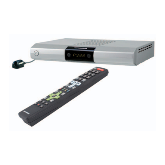
- Page 1 Operating manual DVB Satellite Receiver UFS 640si...
-
Page 2: Preface
For shorter breaks, you can use the remote control to switch the receiver to standby, which uses only a minimal amount of energy. We wish you good reception and much pleasure using your new DVB satellite receiver. Your KATHREIN team... -
Page 3: Important Information
This unit makes use of legally protected technologies, which are protected by patents in the USA and also by other intellectual property rights in other countries. KATHREIN-Werke KG has obtained licences from Audio MPEG Inc. and Societa‘ Italiana per lo sviluppo dell‘elettronica, S.I.SV.EL, S.P.A to use these technologies. -
Page 4: Table Of Contents
... 2 PREFACE IMPORTANT INFORMATION ... 4 CONTENTS SAFETY INSTRUCTIONS - IMPORTANT NOTES RECEIVER FEATURES / DELIVERY SCOPE CONTROLS, DISPLAYS AND CONNECTIONS CONNECTION AND SET-UP UNDER-SHELF MOUNTING MOUNTING ON A FIXED EVEN SURFACE ... 12 REMOTE CONTROL ... 13 FIRST INSTALLATION OPERATING INSTRUCTIONS ... - Page 5 ... 48 EDIT FAVOURITES LISTS REMOVE FROM THE FAVOURITES LIST ... 49 LOCK CHANNELS RENAME FAVOURITES LIST START BLOCKSELECTION (HIGHLIGHTING SEVERAL CHANNELS) SEARCH CHANNELS (CHANNEL SEARCH) AUTOMATIC (CHANNEL) SEARCH MANUAL (CHANNEL) SEARCH CHANNEL SEARCH WITH SERVICE ID ... 56 PARENTAL CONTROL ...
-
Page 6: Safety Instructions - Important Notes
SAFETY INSTRUCTIONS - IMPORTANT NOTES... -
Page 7: Receiver Features / Delivery Scope
12 V, as well as the accessories required for on-surface or under-shelf installation. A variety of features include: Kathrein EPG, guided fi rst installation with national programme lists, electrical audio output for Dolby Digital (AC 3), a video Cinch output and videotext with 800-page memory capacity. -
Page 8: Controls, Displays And Connections
CONTROLS, DISPLAYS AND CONNECTIONS This section provides a brief description of all the controls, displays and connections. VIEW OF FRONT PANEL (FLAP REMOVED) VIEW OF REAR PANEL Front Panel Controls and Displays On/Off switch (with mains disconnect) Channel select buttons - (▼▲) Display Rear Panel Controls and Displays LNB loop-through input... -
Page 9: Connection And Set-Up
The following section is intended specifi cally for specialist dealers. You need not refer to this section unless you are carrying out the installation yourself. The “Connection examples” section provides a sample confi guration. Do not connect the receiver to the power supply until all installation work has been properly carried out. Refer to the information in the “Safety instructions”... -
Page 10: Inserting Batteries Into The Remote Control
Slide the cover back into the housing until it locks in place. MOUNTING THE UFS 640SI WITH A MOUNTING SUPPORT The supplied mounting support enables you to not only place the receiver onto a fi rm, even surface but to fi x it onto or below this surface (under-shelf installation). -
Page 11: Under-Shelf Mounting
UNDER-SHELF MOUNTING Remove the supplied wooden screws from the transportation fi xing on the top of each fi xing bracket (2 each). Fix both mounting brackets to your receiver as illustrated in the illustrations 1-3. The fol- lowing is to be observed: Left(L) and right (R) markings (see ar- rows illustration 2) The notch spacings on the bottom side... -
Page 12: Remote Control
Numeric input for channels, timers etc. Open the main menu, leave the menu and return to the TV picture Volume Sound on/off FAV (red) Open favourites selection PIP (green) “Current” view in the EPG Open EPG (Electronic Programme Guide) Leave the menu step by step Changing channel in the programme preview (EPG) -
Page 13: First Installation
FIRST INSTALLATION: General Before using your receiver for the fi rst time, read the “Safety Instructions” and “Connection and Setup” sections. The “Connection examples” section provides a sample confi guration. Do not connect the receiver to the power supply until all installation work has been properly carried out. - Page 14 FIRST INSTALLATION: General The following display appears: Use the buttons here to select whether you wish to use the pre-programmed channel list (select “no”) or generate a new channel list by searching (select “yes” - you will be asked later in the fi rst installation to compile this list).
- Page 15 FIRST INSTALLATION: General Picture format Here you select the type of screen display, depending on the setting of your TV format: TV format “4:3”: Pan & Scan or Letterbox TV format “16:9”: “Automatic” or “Always 16:9” TV-Scart-Output Select the type of video signal at the TV Scart socket here. Select the signal that your TV set can process. FBAS - composite colour signal or RGB - Red/Green/Blue signal HDMI format...
- Page 16 FIRST INSTALLATION: DiSEqC™1.0 When selecting satellite(s), make sure that your reception position is aligned to the desired satellite(s)! Use the buttons here to switch to the “Number of Satellites” selection Number of Satellites Press the button to select the number of satellites to be received. You can select a number from one to four satellites to be received.
- Page 17 FIRST INSTALLATION: DiSEqC™1.0 The following display appears (example): Satellite and Position Use the buttons to set the desired satellite (selection from 17 pre-programmed options). LNB settings Use the buttons here to select the LNB type used in your system. The choice is between “Universal” and “user-defi...
- Page 18 FIRST INSTALLATION: Simple LNB Satellite and position Use the buttons to select the desired satellite whose signal is to be received by the tuner. When you have selected your desired satellite, use the to switch to the selection of the “LNB Type”.
- Page 19 LNB type used in your system. The choice is between “Universal”, “Wideband” and “Single”. If in your reception system you use a single-cable LNB (e.g. UAS 481 from Kathrein), please select here the setting “Wideband”. If you use a single-cable matrix (EXU 908) or a single-cable changeover matrix (EXR 551 or EXR 552) from Kathrein, the LNB you use must be a “Universal LNB”!
- Page 20 FIRST INSTALLATION: One Cable Universal: No further input is required, since all necessary frequency ranges are covered by a universal LNB. Wideband: No further input is necessary, since all frequency ranges are set by the Wideband LNB. Single: If you are not using a Universal or a Wideband system, you must set the frequencies here. You can fi nd the necessary information in the documentation supplied with your system.
- Page 21 FIRST INSTALLATION: Single-cable system (automatic) If one or more receivers are already present on the system and an additional receiver is to be connected, when assigning the transmission frequency for the new receiver make sure that no transmission frequencies are duplicated. No frequency can be used by more than one receiver.
- Page 22 KATHREIN EXR 552 (single-cable switching matrix, max. four receivers) KATHREIN EXU 908 (single-cable matrix, max. eight receivers) EXR 4 subscriber (for future Kathrein single-cable (switching) matrices, max. four receivers) EXR 8 subscriber (for future Kathrein single-cable (switching) matrices, max. eight receivers) Selection “user-defi...
- Page 23 FIRST INSTALLATION: single-cable system (manual) Test connection When you have completed all the settings, press the buttons to switch to the “Test connection” selection fi eld and press the button. The receiver now tests whether a connection to the single-cable system can be established or not.
- Page 24 FIRST INSTALLATION: single-cable system (manual) Selection “UAS 481” or “EXR 551” When the UAS 481 single-cable feed system is being used, it is essential that the LNB is set to “Wideband”! When the EXR 551 single-cable switching matrix is being used, it is essential that the LNB is set to “Universal”! Transmission channel...
- Page 25 FIRST INSTALLATION: single-cable system (manual) Selection “EXR 552” When the “EXR 552” single-cable switching matrix is being used, it is essential that the LNB is set to “Universal”! Transmission channel Use the buttons to select a free available transmission channel. A maximum of two transmission channels are available (1400 and 1516 MHz).
- Page 26 FIRST INSTALLATION: single-cable system (manual) Selection “EXU 908” When the “EXU 908” single-cable matrix is being used, it is essential that the LNB is set to “Universal”! Transmission channel Use the buttons to select a free available transmission channel. A maximum of eight transmission channels are available (1284, 1400, 1516, 1632, 1748, 1864, 1980 and 2096 MHz).
- Page 27 “free & encrypted”, “only free” or “encrypted only” channels. The UFS 640si does not allow encrypted channels to be viewed, because no Common Interface is fi tted for insertion of the necessary CA modules and smart cards.
- Page 28 FIRST INSTALLATION: Channel Search/Date and time Use the button to move to the next step of the fi rst installation. The following display appears: Local time offset Use the buttons to set the time zone variation from UTC (formerly GMT) (e.g. for Germany +1 hour).
-
Page 29: Operating Instructions
MENU CONCEPT The structure of the menu concept is based on logical operating sequences. The programme showing on the current selected channel always appears in the top right-hand corner of the screen. You will fi nd detailed descriptions of the selected menu items in the relevant sections of the operating manual. -
Page 30: Menu Tree
OPERATING INSTRUCTIONS MENU TREE Main Menu Open the menu by pressing the button... -
Page 31: Alphanumeric Inputs
OPERATING INSTRUCTIONS ALPHANUMERIC INPUTS Use the displayed keypad (see fi gure to the right) for entry of favourites names or search expressions by selecting numerals for the desired letters / digits. You can write with upper or lower case letters ( button). -
Page 32: On-Screen Displays (Osd)
ON-SCREEN DISPLAYS (OSD) CHANNEL MESSAGES TV CHANNEL MESSAGES $ = encrypted channel Channel number from the overall list Number of soundtracks (yellow) button Display of start time for current and next programmes Channel information is shown for a few seconds each time the channel is changed (this can be changed under “Settings”, “Customize screen menu”) or displayed continuously by pressing the RADIO CHANNEL MESSAGES The information for the current radio channel has the same layout. -
Page 33: Option Selection
ON-SCREEN DISPLAYS (OSD) Select the channel using the channel directly using the OPTION SELECTION Press the (yellow) button once (twice for portal channels) to view further audio selection options, if these are transmitted by the channel provider. Use buttons to scroll through the available selection options. - Page 34 ON-SCREEN DISPLAYS (OSD) Underneath you can see the channel list with the sort order you selected. The channel list can display channels sorted by various selection and sorting criteria. Selection and sorting options: Press the (red) button to open the favourites list selection. The through the existing favourites lists Press the (green) button to return to the overall list (all satellites).
-
Page 35: Epg - Electronic Programme Guide
EPG - ELECTRONIC PROGRAMME GUIDE CALLING UP THE EPG The EPG is opened by pressing the shown the “Current” view, irrespective of which view you were shown the last time you left the EPG. The following display appears (example): Current programme Note: If you selected a favourites list before opening the EPG, you will see in the EPG only the data for... -
Page 36: Current" View
EPG - ELECTRONIC PROGRAMME GUIDE Selection options: (red) button Open the timer list (display of all pre-programmed recordings) (yellow) button Open the “EPG” view (green) button Open the “Current” View button Changing the channel in the “EPG” view button Next programme in the “Current” view button (P+) jump forwards 24 hours in the EPG, (P-) jump backwards 24 hours... -
Page 37: Preview" View (Programme Listings)
EPG - ELECTRONIC PROGRAMME GUIDE Pressing the button displays the next programme (“Next” view); pressing the the “Current” view. If you wish to view the programme currently being shown on a channel, you need not exit the EPG, just select the desired channel. At the top right of the screen you will see the current TV picture for the selected channel. -
Page 38: Additional Information (I Button)
EPG - ELECTRONIC PROGRAMME GUIDE ADDITIONAL INFORMATION (i BUTTON) The additional information can always be called up by pressing button whenever the “i symbol” appears in front of the programme name (see screenshot on the right). First however the channel must be selected. The following display appears (example): The additional information available for a programme is displayed in its own window. -
Page 39: Recording (Timer)
EPG - ELECTRONIC PROGRAMME GUIDE RECORDING (TIMER) (red dot) button allows you to set up a programme at any time for recording on an external recorder. The programme to be recorded can be selected in any of the EPG views, provided the appears at the bottom of the screen display. -
Page 40: Record Once
EPG - ELECTRONIC PROGRAMME GUIDE RECORD ONCE Use the buttons to select the recording mode “once” (see screenshot “Recording (timer)” section). Use the buttons to switch to the selection fi eld “Date” and use the desired recording day. Use the buttons to switch to the selection fi... -
Page 41: Record Weekly
EPG - ELECTRONIC PROGRAMME GUIDE RECORD WEEKLY Remember that the day of the week for the desired programme is loaded in the recording list and you can make no further manual corrections to it! Therefore before pressing (red dot) button, select the programme on the day of the week that in future you will wish to make the weekly recording. -
Page 42: Plan Recording
EPG - ELECTRONIC PROGRAMME GUIDE PLAN RECORDING The “Recording schedule” view can be called up at any time in EPG by pressing the The timer list view shows you all the recordings that are scheduled. buttons allow the recordings to be sorted into “once” or “repeated” recordings. The cursor buttons ( The cursor buttons ( ) allow you to select a recording. -
Page 43: Videotext (Teletext)
This symbol in the channel notifi cation shows you whether Videotext/Teletext is available for the selected channel. When you press the button, the receiver processes the videotext/Teletext service data for your TV set to display, even when the signal is encrypted. When the search is fi... -
Page 44: Edit Channel List
Select the “Edit channel list” menu using the Also pay attention to the bars at the bottom of the on-screen display! These provide information on what to do next. Press the button to close the information display for editing channels and channel lists. When the menu is opened, the standard setting is for the receiver to show the “All Satellites”... -
Page 45: Editing Lists / Channels
EDITING LISTS / CHANNELS When you have selected the channel or channel list to be edited, press the edit menu. You have the following edit options: Move: Channel can be moved within the current list to another channel slot Delete: Delete the channel from the current list Skip: Channel will be skipped when zapping through the channels... -
Page 46: Last Function" Memory
“LAST FUNCTION” MEMORY The last editing action performed is saved on the the last selection to other channels without having to open the edit menu again. As soon as you leave the current display, this option is cleared and becomes available again only after the edit menu has been opened and an action selected. -
Page 47: Lock Channels
EDIT CHANNEL LIST LOCK CHANNELS Use the buttons to select the channel to be locked on the channel list you have selected. Press the button to open the edit menu and use the buttons to select the “Lock” function. Confi rm the command by pressing the button. -
Page 48: Edit Favourites Lists
EDIT FAVOURITES LISTS When you have selected the favourites list to be edited (called up using the using the buttons), press the edit options: Remove from favorites list: The channel will be removed from the favourites list Llock: Channel can be viewed only by entering a PIN Rename favorites list: The favourites list can be renamed Start Blockselection:... -
Page 49: Lock Channels
EDIT CHANNEL LIST LOCK CHANNELS Use the buttons to select the channel to be blocked in the favourites list you have selected. Press button to open the edit menu and use the buttons to select the “Lock” function. Confi rm the command by pressing the button. -
Page 50: Search Channels (Channel Search)
SEARCH CHANNELS (CHANNEL SEARCH) Select the “Channel search” menu using the Also pay attention to the bars at the bottom of the on-screen display! These provide information on what to do next. You have three options for a channel search. Automatic Channel Search –... - Page 51 SEARCH CHANNELS (CHANNEL SEARCH) Satellite Using the buttons, select the satellite to be scanned. Make sure your reception system is aligned to the selected satellite. You can search only one satellite at a time. If you have connected a multi-feed reception system (e.g.
-
Page 52: Manual (Channel) Search
SEARCH CHANNELS (CHANNEL SEARCH) Newly found channels are identifi ed with the designation “New” after the channel name. After completion of the search, you will see the following message (example): Press the button You will be asked whether you wish to save the changes or not. Use the buttons to make the selection and confi... - Page 53 SEARCH CHANNELS (CHANNEL SEARCH) buttons allow you to select different sets of parameters for the scan. Satellite Use the buttons to select the satellite on which the transponder you wish to scan is located. Make sure your reception system is aligned to the selected satellite. You can search only one transponder at a time.
-
Page 54: Channel Search With Service Id
SEARCH CHANNELS (CHANNEL SEARCH) After completion of the search, you will see the following message (example): Press the button You will be asked whether you wish to save the changes or not. Use the buttons to make the selection and confi rm the selection with the button. - Page 55 SEARCH CHANNELS (CHANNEL SEARCH) Make sure your reception system is aligned to the selected satellite. Press the button to move to the next selection item. Transponder frequency Use the buttons or the keypad to select the transponder frequency on which the channel being sought is transmitted.
-
Page 56: Parental Control
Select the “Parental Control” menu using the menu button menu and . You are now prompted to enter the PIN code (factory default setting: 0000). After entering the PIN using the keypad you are shown the following display: Also pay attention to the bars at the bottom of the on-screen display! These provide information on what to do next. -
Page 57: Define New Pin Code
DEFINE NEW PIN CODE Press to replace the old PIN with a new one. Enter the new (four digit) PIN. For security you must repeat the new PIN code once again. Confi rm the change of PIN code by pressing the Keep your PIN code in a safe place, so that you always have access to your channels should you ever forget it. -
Page 58: Settings
The selected menus, sub-menus and positions, as well as the parameters to be set, are each highlighted in colour. The menus are largely self-explanatory. Pay attention to the bar at the bottom of the on-screen display. These provide information on what to do next. -
Page 59: Tv Settings (Tv, Picture And Sound)
TV SETTINGS (TV, PICTURE AND SOUND) TV ASPECT RATIO Here you can use the 4:3 or 16:9 format. PICTURE FORMAT Use the buttons here to select the type of screen display. • Pan & Scan • Letterbox • Full-screen image TV-SCART-OUTPUT Here you can use the the signal that your TV set can process. -
Page 60: Customize Screen Menu
CUSTOMIZE SCREEN MENU FUNCTIONAL RANGE Here you can confi gure the functional scope of your receiver. You can choose between “Complete”, “Simple” and “Medium”. The following table shows which functions are available at each confi guration step. - (red) button High Select favourites Not assigned... -
Page 61: Date And Time
SETTINGS DATE AND TIME Local time offset Use the buttons to set the time zone variation from UTC (formerly GMT) (e.g. for Germany +1 hour). Use the buttons to switch to the “Automatic clock change” fi eld. Automatic clock change Use the buttons to select whether the receiver should automatically change over to and from summer and winter time. -
Page 62: Service Menu
SERVICE MENU Select the “Service” menu using the button, the buttons in the main menu and . The following display appears: Current software version Hardware version Last update run Date of the channel list UPDATING SOFTWARE You can also check manually whether new software is available. Use the buttons to switch to “Software Update”... - Page 63 Also pay attention to the bars at the bottom of the on-screen display! These provide information on what to do next. Updating software If new software is available (but only then), use the load the new software that is available. If you are unsure whether you wish to load the new software, you can initially set the reply to “No”.
-
Page 64: Restore Factory Settings
SERVICE MENU The following display appears (example): RESTORE FACTORY SETTINGS Select the “Service” menu using the button, the buttons in the main menu and . Use the buttons to switch to “Restore factory settings” and to call them up press the button. -
Page 65: Connecting Up The Video/Dvr
(see “EPG” “Recording (timer)” section). PLAYBACK For VCR/DVR playback you must have previously set the UFS 640si Scart socket to “VCR mode” (Scart changeover), using the button, so that the signal path is set up from the VCR or DVR/AUX Scart socket to the TV Scart socket. -
Page 66: Using The Front Panel/Service
USING THE FRONT PANEL/SERVICE If you have misplaced your remote control, or if the batteries are fl at, you can still operate your receiver from the front panel. BACKUP OPERATION There are two buttons on the front of the receiver. ▼... -
Page 67: Technical Appendix
TV set for optimal viewing comfort Upscaler to upscale Pal signals (576i) to 576p, 720p and 1080i 4-digit display Kathrein EPG with timer programming ¹ Antenna level shown on TV (optically and acoustically) for manual align-ment of a parabolic refl ector (Sat Finder) Guided fi... - Page 68 Perm. ambient temperature Dimensions Weight TECHNICAL APPENDIX dBµV CCIR 601 (720 x 576 lines), 576p, 720p, 1080i MSymb/s V/mA 22; DiSEqC °C UFS 640si 20210138/silver 950-2,150 44-83 < 4.5 DVB-S standard 2-45 > 53 MPEG-1 and MPEG-2, Layer 1 and 2 32/44.1/48 >...
-
Page 69: Scart Socket Assignment
SCART SOCKET ASSIGNMENT Signal Right audio output Right audio input Left audio output Audio earth Blue earth Audio left input Blue signal Switching voltage Green earth Data signal Green signal Data signal Red earth Data earth Red signal (C) Blanking signal Video earth Blanking signal earth Video output (FBAS/Y) -
Page 70: Connection Example
CONNECTION EXAMPLE Scart Digital audio AC Digitalton AC 3 3 electrical elektrisch TECHNICAL APPENDIX Dolby digital system Hi-fi system Infra-red receiver Infrarot-Empfänger (optional) (optional) Scart... -
Page 71: Examples Of Single-Cable Systems
EXAMPLES OF single-cable systems EXR 501/551/552 Single-cable switching matrices ESU 33 ERA 14 Single RTL Television ESU 33 ERA 14 Single RTL Television TECHNICAL APPENDIX ESU 33 ESU 33 Single Single RTL Television RTL Television ERA 14 ESU 33 Single RTL Television Terrestrial Terrestrische... - Page 72 TECHNICAL APPENDIX UAS 481 Single-cable feed system ERA 14 ERA 14 ERA 14...
- Page 73 EXU 908 Single cable matrix ESU 33 ESU 33 ERA 14 Single RTL Television RTL Television ESU 33 ERA 14 Single RTL Television TECHNICAL APPENDIX UAS 484/ Quatro-LNB UAS 584 UAS 484 ESU 33 ESU 33 Single Single Single RTL Television RTL Television ESU 33 ESU 33...
-
Page 74: Short Technical Guide
SHORT TECHNICAL GUIDE CHANNEL PACKAGE The channel package for a digital transponder normally includes several TV and radio channels. Each channel package has a fi xed assignment for the transponder transmission frequency, for polarisation (horizontal or vertical), for the symbol rate and for the Viterbi rate or error rate. DISEQC™... -
Page 75: Symbol Rate
SHORT TECHNICAL GUIDE The PID (Packet IDentifi cation) number is an identifi cation number for video signals and audio signals in the digital data stream of DVB-MPEG -2 signals. The receiver uses the PID number to create a unique assignment for the video and audio data transmission. The PCR PID is the identifi cation number for the synchronisation signal. -
Page 76: Glossary
GLOSSARY AC 3 Output for Dolby Digital signal Audio output Sound output on the receiver AV programme pos. Preferred programme position on TV set for Scart input Conditional Access (for decoding encrypted programmes) Internationally standardised interface for CA modules Decoder Decoder for Pay TV DiSEqC™... -
Page 77: Troubleshooting
In the event of a malfunction, fi rst check all the cable connections and operating states: 1. Receiver and TV set power plugs are connected to wall socket 2. Antenna cables on receiver input 3. Receiver and TV set correctly connected by a Scart or cinch cable 4. -
Page 78: For Your Notes
FOR YOUR NOTES... - Page 79 FOR YOUR NOTES...
- Page 80 Internet: http://www.kathrein.de KATHREIN-Werke KG • Anton-Kathrein-Straße 1 - 3 P.O. Box 100 444 • 83004 Rosenheim • GERMANY...
Need help?
Do you have a question about the UFS 640si and is the answer not in the manual?
Questions and answers