Table of Contents
Advertisement
Advertisement
Table of Contents

Related Manuals for Hillrom Centuris P750


Summary of Contents for Hillrom Centuris P750
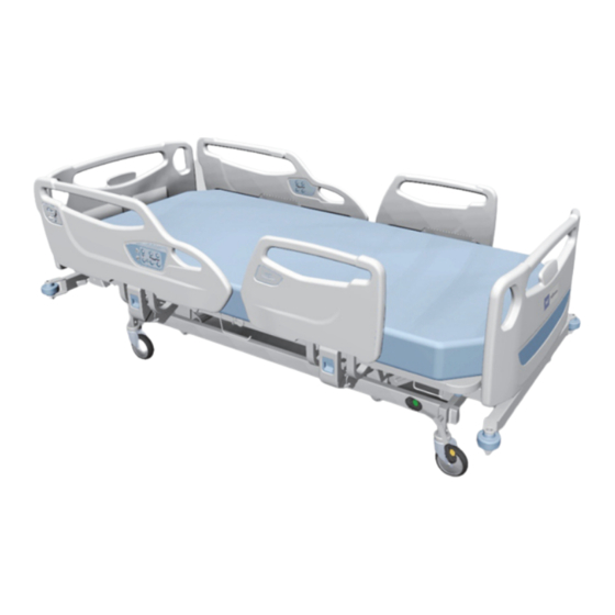
- Page 1 Centuris™ Bed System Instructions for Use Product No. P750...
-
Page 3: Revision
© 2021 by Hill-Rom Services PTE. Ltd. ALL RIGHTS RESERVED PATENTS / PATENT hillrom.com/patents May be covered by one or more patents. See the Internet address above. The Hillrom companies are the proprietors of European, US, and other patents and pending patent applications. - Page 4 Replace this manual (179643) if it is damaged and/or can not be read. For product support or to order additional copies of this manual (179643), contact your distributor, local Hillrom representative, or go to hillrom.com. Reference Documents Centuris™ Bed Service Manual (179644) Centuris™...
-
Page 5: Table Of Contents
Table of Contents Revision..................i Intended Use . - Page 6 Table of Contents Patient Controls ................1 - 17 Frame Features .
- Page 7 Table of Contents Decommissioning and Disposal Instructions..........1 - 31 Expected Life.
- Page 8 Table of Contents NOTES: Centuris™ Bed System Instructions for Use (179643 REV 8)
-
Page 9: Intended Use
Intended Use INTENDED USE The Centuris™ Bed System is intended for use in healthcare environments such as acute care and critical care. Bed safe working load—204 kg maximum, this includes patient weight, mattress, IV pumps, poles, bags, and other equipment. NTENDED ATIENT OPULATION... -
Page 10: Symbols
Symbols SYMBOLS OCUMENT YMBOLS This manual uses different typefaces and symbols to make the content easier to read and understand: • Standard text—used for regular data. • Boldface text—emphasizes a word or phrase. • NOTE:—sets apart special data or important instruction clarification. •... - Page 11 Symbols Symbol Description Do Not Use with Oxygen Tents—use oxygen administering equipment of the nasal, mask, or ventilator type only. Alternating current Safe working load—for the bed and accessories Total bed weight including the safe working load Maximum patient weight Duty cycle Dangerous voltage Fuse...
- Page 12 Symbols Symbol Description Environmental Protection: Waste electrical products should not be disposed of with household waste. Please recycle where facilities exist. Check with your Local Authority or a retailer for recycling advice. (Applicable on the backup battery) Batteries should not be disposed of with household waste.
- Page 13 Symbols Symbol Description Indicates handle for lowering the backrest in an emergency to do cardiopulmonary resuscitation (CPR). Indicates Neutral and Brake position of the brake/steer pedal (individual brake caster beds only). Indicates Neutral/Brake/Steer position of the brake steer pedal (foot end brake/steer beds only).
-
Page 14: Safety Information
Safety Information SAFETY INFORMATION WARNING: WARNING: Obey all warnings throughout the manual and also those below to help prevent injury and/or equipment damage: • Warning—Make sure the bed is connected to AC power and works correctly before you put a new patient on the bed. -
Page 15: Siderails
Siderails are intended to be a reminder to the patient of the unit’s edges, not a patient-restraining device. When appropriate, Hillrom recommends that medical persons determine the correct methods necessary to make sure that the patient remains safely in bed. -
Page 16: Electrical Safety
• Warning—To reduce the risk of electric shock, the bed should only be connected to supply mains with a power cord with protective earth, supplied by Hillrom. • Warning—Incorrect use or handling of the power cord may cause damage to the power cord. If damage has occurred to the power cord, immediately remove the bed from service, and contact the applicable maintenance persons. -
Page 17: Transport
Safety Information RANSPORT WARNING: WARNING: To help prevent injury and/or damage to the equipment during transportation, obey these warnings: • Warning—The bed is intended to be used to transport patients with the foot end or head end of the bed forward. Before transport, correctly store the power cord to help prevent tripping. Use only the end panels to move the bed during transport. -
Page 18: Features
Features FEATURES Item Description Equipment sockets Head angle indicator Power cord storage End panel—Headboard Patient controls Siderails End panel—Footboard Corner bumpers Casters, 12.5 cm Four-corner brake pedal or foot-end brake and steer bar Siderail release lever Bed angle indicator Drainage holder Caregiver controls Emergency CPR handle Centuris™... -
Page 19: Caregiver Controls
Caregiver Controls These features may or may not be on the Centuris™ Bed System: • Battery backup function • Four DC motors • Complete bed articulation: bed, head, and knee up/down, Trendelenburg/Reverse Trendelenburg, and Auto Contour™ Feature • Lockout controls CAREGIVER CONTROLS This section describes the bed controls that are intended to be used by the caregiver. -
Page 20: Raise And Lower The Siderails
Caregiver Controls AISE AND OWER THE IDERAILS WARNING: WARNING: Warning—Evaluate patients for entrapment risk in accordance with facility protocol, and monitor patients appropriately. Make sure all siderails are fully latched when in the raised position. Failure to do either of these could cause serious injury or death. NOTE: Siderails are intended to be a reminder to the patient of the unit’s edges, not a patient-restraining device. -
Page 21: Caregiver Siderail Controls
Caregiver Controls AREGIVER IDERAIL ONTROLS NOTE: Caregiver siderail controls are not available on configurations shipped with the caregiver pendant controls. WARNING: WARNING: Warning—Before you lower the bed, look under the bed to make sure there are no people or obstructions between the lower and upper frames of the bed. Failure to do so could cause serious injury or equipment damage. -
Page 22: Raise And Lower The Knee Section
Caregiver Controls Raise and Lower the Knee Section Knee Up Press and hold the Knee Up control to raise the knee section. The knee section can rise to 25°. When the knee section goes up or down, the foot section will also go up or down. Press and hold the Knee Down control to lower the knee section. -
Page 23: Lockout Controls
Caregiver Controls Lockout Controls WARNING: WARNING: Warning—Locking the controls can significantly reduce the potential for unintentional movement. If a patient’s condition is such that injury could occur from unintentional movement, lock out the patient controls. Failure to do so could result in patient injury or equipment damage. To lock—... -
Page 24: Lockout Pendant Controls
Caregiver Controls To remove from the siderail— • Pull the pendant straight up. • Turn the pendant clockwise or counterclockwise until the mount clip disengages from the siderail or footboard. To store— WARNING: WARNING: Warning—The pendant should not be stored under the mattress. -
Page 25: Patient Controls
Patient Controls PATIENT CONTROLS The patient controls are on the inside of the head-end siderails. They function in the same way as the caregiver controls. See “Caregiver Siderail Controls” on page 13. NOTES: • Caregivers shall provide the necessary instructions and warnings to the patient or visitor on how to use the bed safely. -
Page 26: Frame Features
Frame Features FRAME FEATURES QUIPMENT OCKETS An IV pole can be installed in any of the four equipment sockets located at the four corners of the bed. ANELS EADBOARD AND OOTBOARD The bed has mount holes for the bed end panels. WARNING: WARNING: Warning—When you install the end panels, make... -
Page 27: Drainage Bag Holders
Frame Features RAINAGE OLDERS Drainage bag holders are on both sides of the bed. Each drainage bag holder can support up to 4 kg. RAKE TEER There are two configurations of brake and steer: Foot-end and Individual. WARNING: WARNING: Warning—Except for transporting a patient, always set the brakes when the bed is occupied. Make sure that the brakes are set before you move the patient from the bed. -
Page 28: Patient Restraint Straps
When the battery charge level is not sufficient enough to operate the bed, and a control is pressed, an alarm sounds. Connect the bed to AC power to recharge the battery. 1. The mattress foot extender pad is not sold with this product. Contact Hillrom Technical Support for compatible foot extender pads. - Page 29 Warning— Exposure of the battery to an impact (for example, a collision, a powerful stroke or dropping it on the floor) may lead to an explosion when the battery is in use. Remove the bed from service immediately and contact Hillrom Technical Support. •...
-
Page 30: Battery Disposal
Before the bed is used for the first time, charge the battery for at least 24 hours or longer. Battery Disposal The battery backup power comes from a lead acid battery.Hillrom recommends replacing the battery every three years. Recycle the battery in accordance to your local regulations. -
Page 31: Mattress Retainers
Frame Features ATTRESS ETAINERS There are three mattress retainers on the bed. One on each side of the sleep deck and one at the foot end of the sleep deck. The retainers help the mattress to stay in the correct position on the bed. OWER ANAGEMENT WARNING:... -
Page 32: Adjustable Foot Panel
Frame Features DJUSTABLE ANEL The foot panel can be placed in two different positions and is held in place by the mechanical notches. Position 1: The foot panel is leveled. Position 2: The foot panel is inclined. Centuris™ Bed System Instructions for Use (179643 REV 8) -
Page 33: Accessories
Accessories ACCESSORIES WARNING: WARNING: Warning—Use of accessories that are not listed below might lead to patient injury or equipment damage. Caregivers shall perform the risk assessment and mitigation based on the facility protocol. Accessories Part Number Description P1445A Removable IV pole P145920 Removable IV pole (offset style) P145910... -
Page 34: Removable Iv Pole (P145920-Offset Style)
Accessories Removable IV Pole (P145920—Offset Style) Each hook on the IV pole (P145920—Offset Style) can hold a weight of 2 kg. To install— 1. Insert the IV pole vertically into any of the equipment sockets at either the head end or foot end of the bed. 2. -
Page 35: Patient Helper (P145911)
Accessories (P145911) ATIENT ELPER The Patient Helper installs in the center equipment socket at the head end of the bed. WARNING: WARNING: Warning—Do not exceed the load capacity of the Patient Helper. If the Patient Helper is overloaded, injury or equipment damage may occur. -
Page 36: Cleaning And Disinfecting
The trainer should supervise the trainee until the trainee can clean and disinfect the bed as instructed. Hillrom recommends to clean and disinfect the bed and mattress before first use, between patient use, and regularly during extended patient stays. -
Page 37: Cleaning And Disinfection
Cleaning and Disinfecting LEANING AND ISINFECTION Cleaning and disinfection are distinctly different processes. Cleaning is the physical removal of visible and non-visible soil and contaminants. Disinfection is intended to kill microorganisms. Recommended Cleaning/Disinfectants Solutions Chemical Class Active Ingredient Quaternary ammonium chloride Didecyl dimethyl ammonium chloride Alkyl dimethyl benzyl ammonium chloride Quaternary ammonium... -
Page 38: Step 2: Disinfection
• Zipper closure d. If any of these items are damaged, replace the mattress. See “Compatible Mattresses from Hillrom” on page 22. STEP 2: Disinfection a. With a new or clean wiping cloth soaked in a recommended cleaner/disinfectant, use light pressure to wipe all exterior surfaces of the bed previously cleaned. -
Page 39: Maintenance
• If the decommissioned bed or accessory is not fit for use, Hillrom recommends dismantling the bed in accordance with the instructions provided in the service manual. Hillrom recommends that all oil and hydraulic fluids are removed from the product before recycling or disposal, if applicable. -
Page 40: Expected Life
Other components, such as electronic components, plastics and metals, are recyclable in many local jurisdictions. Hillrom recommends recycling all components that can be recycled locally. Components which cannot be recycled can be disposed of via standard waste disposal procedures. -
Page 41: Technical Specifications
Technical Specifications TECHNICAL SPECIFICATIONS Product Identification Product Number Description P750 Centuris™ Bed System Dimensions Feature Dimension Length—fully retracted 220 cm Length—fully extended 230 cm Sleep deck length 196 cm Minimum width—with siderails raised 100 cm Maximum width—with siderail stored 105.5 cm Sleep deck width 86.4 cm Maximum head end panel height... - Page 42 Technical Specifications Environmental Conditions for Transport and Storage Condition Range Temperature -40°C to 70°C ambient temperature Relative humidity (RH) 20% to 95%, non-condensing Pressure 50 kPa to 106 kPa Environmental Conditions for Use Condition Range Temperature 5°C to 40°C ambient temperature Relative humidity (RH) 30% to 90%, non-condensing Atmospheric pressure...
-
Page 43: Electromagnetic Compatibility
Technical Specifications Application Environments: Environments 1 and 2 as per EN and IEC 60601-2-52 Classification according to European Union Class I Medical Device Regulation (EU) 2017/745 Degree of protection against the presence of Not for use with flammable anesthetics. flammable anesthetic mixtures IPX classification IPX4—According to IEC 60529, rating for protection against fluid ingress and identified as equipment that... - Page 44 Technical Specifications Electromagnetic Emissions Guidance Guidance and Manufacturer's Declaration—Electromagnetic Emissions The P750 is intended for use in the electromagnetic environment specified below. The customer or the user of the P750 should make sure it is used in such an environment. Emissions Test Compliance Electromagnetic Environment—Guidance...
- Page 45 Technical Specifications Guidance and Manufacturer's Declaration - Electromagnetic Immunity The P750 is intended for use in the electromagnetic environment specified below. The customer or the user of the bed should make sure it is used in such an environment. Immunity Test IEC 60601-1-2 Test Level Compliance Level Power frequency...
- Page 46 Technical Specifications NOTES: Centuris™ Bed System Instructions for Use (179643 REV 8)
Need help?
Do you have a question about the Centuris P750 and is the answer not in the manual?
Questions and answers