
Related Manuals for Videotec MAXIMUS MVX


Summary of Contents for Videotec MAXIMUS MVX
- Page 1 ENGLISH MAXIMUS MVX, MAXIMUS MVXT, MAXIMUS MVXHD Ex-proof stainless steel housing anual English - Instruction manual...
-
Page 3: Table Of Contents
Contents E N G L I S H 1 About this manual ........................7 1.1 Typographical conventions ..............................7 2 Notes on copyright and information on trademarks ............7 3 Safety rules ..........................7 3.1 ATEX-IECEx certificate details............................10 3.1.1 Temperature ......................................10 3.1.2 Characteristics of installable cameras ............................10 3.1.3 Installation instructions ..................................10 3.1.4 Installation options .................................... - Page 4 13.2 Cleaning the germanium window..........................32 13.3 Cleaning the product ...............................32 14 Information on disposal and recycling ................33 15 Troubleshooting ........................33 16 Technical data ........................34 16.1 MAXIMUS MVX ..................................34 16.1.1 Mechanical ......................................34 16.1.2 Cable glands ......................................34 16.1.3 Housing's window....................................34 16.1.4 Electrical........................................34 16.1.5 Network ........................................34...
- Page 5 16.2.5 Network ........................................36 16.2.6 Serial communications ..................................36 16.2.7 I/O interface ......................................37 16.2.8 Cameras ........................................37 16.2.9 Environment ......................................37 16.2.10 Certifications ......................................37 16.3 MAXIMUS MVXHD ................................38 16.3.1 Mechanical ......................................38 16.3.2 Cable glands ......................................38 16.3.3 Housing's window ....................................38 16.3.4 Electrical .........................................38 16.3.5 Network ........................................38 16.3.6 I/O interface ......................................38 16.3.7 Cameras ........................................38 16.3.8 Environment ......................................38...
- Page 6 MNVCMVXTHD_2222_EN...
-
Page 7: About This Manual
1 About this manual 3 Safety rules Read all the documentation supplied carefully CAUTION! The external equipotential before installing and using this product. Keep the connections must be set up through the manual in a convenient place for future reference. eyelet on the outside of the product. - Page 8 • Device shall be supplied by PS2 energy source. CAUTION! This device must be connected • To feed the product use a safety transformer to an earth conductor (protective earth). and/or a voltage isolated power supply with the The connection must be made only appropriate characteristics.
- Page 9 • This device was designed to be permanently • Installation category (also called Overvoltage secured and connected on a building or Category) specifies the level of mains voltage on a suitable structure. The device must be surges that the equipment will be subjected permanently secured and connected before any to.
-
Page 10: Atex-Iecex Certificate Details
3.1 ATEX-IECEx certificate details 3.1.1 Temperature The relation between ambient temperature range, gas group and Ex code is as follows: MARKING DETAILS Ambient temperature ATEX marking IECEx marking -60°C≤ Ta≤+65°C II 2 G Ex db IIC T5 Gb Ex db IIC T5 Gb II 2 D Ex tb IIIC T100°C Db IP66/IP68 Ex tb IIIC T100°C Db IP66/IP68 -50°C≤... -
Page 11: Installation Options
• The cameras to be installed shall not contain cells The MAXIMUS MVX housing are made of micro shot or batteries. peened AISI 316L stainless steel. • The cameras must have basic geometric shapes. -
Page 12: Product Marking Label
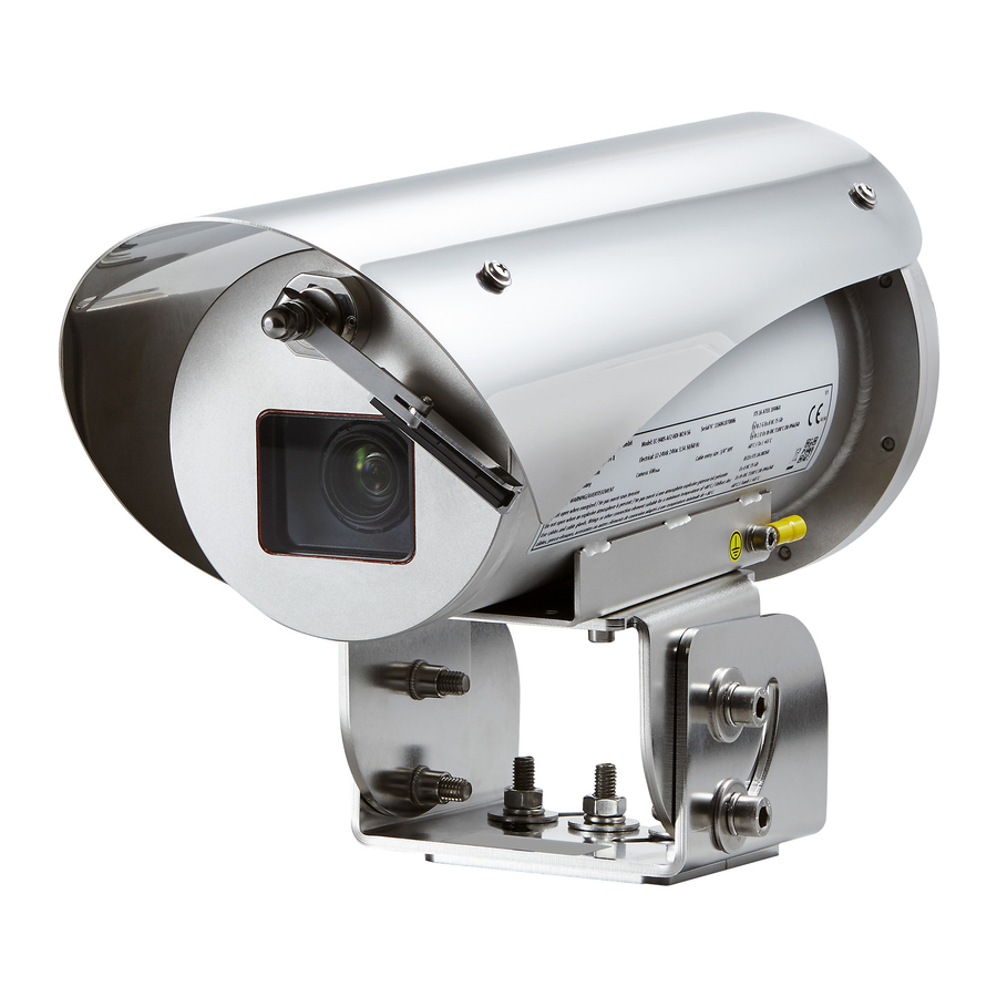
4.2 Product marking label Fig. 2 CE mark and number of notified body that carries out production checks. Manufacturer’s name and address. Model identification code. Ambient temperature of use referring to model identification code Serial number (the second and the third digits define the year of manufacture) Supply voltage (V) Current consumption (A) Frequency (Hz) - Page 13 11. IECEx certification: • IECEx certificate number • Classification for zone type, protection method and temperature class for which this product may be used in compliance with the IECEx standard IECEX MARKING Ambient temperature Gas marking Dust marking -60°C to +65°C Ex db IIC T5 Gb Ex tb IIIC T100°C Db -50°C to +65°C...
-
Page 14: Product Coding
EN - English - Instruction manual 5 Product coding MAXIMUS MVX - PRODUCT CODING Voltage Camera Accessories Connection Video output Model Release 12Vdc-24Vdc/24V Without camera Without accessori- Without cable, Analog T5 -60°C/+65°C First release without cable gland Pre-installed With wiper Connection IP H.264... - Page 15 MAXIMUS MVXHD - PRODUCT CODING Voltage Camera Accessories Connection Video output Model Release MVXHD 12Vdc-24Vdc/24V Without camera Without accessori- Without cable, Without video T5 -60°C/+65°C First release without cable encoder gland Pre-installed With wiper Connection IP H.264 T5 -50°C/+65°C Second release camera devices T6 -60°C/+55°C...
-
Page 16: Versions
6 Versions 6.3 Germanium window 6.1 Tempered glass When the unit is working the protection grid must always be installed. Failure to The product can be equipped with tempered glass. follow this instruction may create serious safety hazards for people and for the installation, and will also invalidate the warranty. -
Page 17: Preparing The Product For Use
7 Preparing the product for Make connections and tests in the laboratory before carrying out installation on site. Use appropriate tools for the purpose. Any change that is not expressly approved by the manufacturer will invalidate both Before proceeding with any operations, the warranty and certification. -
Page 18: Unpacking
7.2 Unpacking 7.5 Preparatory work before installation When the product is delivered, make sure that the package is intact and that there are no signs that it Use appropriate tools for the installation. has been dropped or scratched. The particular nature of the site where the If there are obvious signs of damage, contact the device is to be installed may mean special supplier immediately. -
Page 19: Parapet Mounting
7.5.1 Parapet mounting 7.5.2 Fixing with wall mount bracket First of all secure the base of the adapter to the final The bracket can be fixed to the vertical wall. Use destination. Use screws that can bear at least 4 times screws and wall fixing devices that can bear at least the weight of the unit. -
Page 20: Fixing The Unit To The Pole Mount Adapter Or Corner Mount Adapter
7.5.3 Fixing the unit to the pole mount 7.5.3.2 Fixing with corner adapter adapter or corner mount adapter Fix the wall bracket to the corner mount adapter using 4 washers, 4 stainless steel grower washers To install the product on a pole or at a wall corner, 4 hexagon stainless steel bolts (A4 class 70) first of all fix the unit to the wall bracket (7.5.2 Fixing M10x30mm. -
Page 21: Assembly
The housing can be installed in any position. The cameras to be installed shall not contain cells or batteries. VIDEOTEC strongly recommend to test Fig. 12 the device configuration and performance before putting it in the final installation site. -
Page 22: Control Board Description
8.3 Control board description 8.4 Connector board description BOARD DESCRIPTION BOARD DESCRIPTION Connector/ Function Connector/ Function Terminal Terminal Power supply line/Video signal (analog Video output (digital) camera) Video output (camera) Wiper sensors Power supply line (IP video encoder) Relays and alarm (camera) Power supply line (housing) Power supply line (blower) Video output (analogic) -
Page 23: How To Install The Camera
8.5 How to install the camera 8.6 Connection of the camera CONNECTION OF THE CAMERA The cameras to be installed shall not contain cells or batteries. Version Power supply Video signal Communica- tion lines For additional information on installable Generic IP J13 (connec- Camera –... -
Page 24: Installation
The cameras to be installed shall not atmosphere. contain cells or batteries. Make sure that all the equipment are VIDEOTEC strongly recommend to test certified for the application and for the device configuration and performance the environment in which they will be before putting it in the final installation installed. -
Page 25: Connection Of The Connector Board
9.2 Connection of the connector Earth cable should be about 10mm longer board than the other two, so that it will not be disconnected accidentally if pulled. 9.2.1 Connecting the power supply The power supply cable must be covered Electrical connections must be performed by the silicone sheath (01) supplied. -
Page 26: Video Cable Connection
9.2.2 Video cable connection 9.2.3 I/O cable connection CAUTION! In order to reduce the risk of CAUTION! TNV-1 installation type. The fire, only use cables with sections greater installation is type TNV-1, do not connect it than or equal to 0.14mm² (26AWG). to SELV circuits. -
Page 27: Relays Connection
9.3 Ground connection 9.2.3.2 Relays connection The relay can be used with the CAUTION! The external equipotential specifications outlined below. Working connections must be set up through the voltage: up to 30Vac or 60Vdc. Current: 1A eyelet on the outside of the product. Do max. -
Page 28: Housing Closure
9.4 Housing closure The screws must always be fixed using the provided washers. Test system operation for positive results before closing the product and allowing Pay attention to the fixing. Tightening the presence of a hazardous atmosphere. torque: From 8Nm up to 9Nm. During opening and closure operations of the product, pay attention not to damage the flameproof joint. -
Page 29: Instructions For Safe Operation
The device must be installed only and exclusively by carefully before starting the installation. qualified technical personnel. VIDEOTEC strongly recommend to test the device 10.1.3 Explosion prevention rules configuration and performance before putting it in Use appropriate tools for the area in which you are the final installation site. -
Page 30: Switching On
VIDEOTEC. Make sure that all parts are fastened down Whenever replacing the parts as indicated, firmly and safely. always use VIDEOTEC original spare parts and meticulously follow the maintenance instructions supplied with every spare parts kit. Contact the manufacturer for information on the dimensions of the explosion proof joint. -
Page 31: Fuses Replacement
In the event of o-ring gasket deterioration replace type and rating of fuse. Fuses must be it using the gasket supplied. Use only VIDEOTEC replaced only by service personnel. original spare parts. -
Page 32: Cleaning
13 Cleaning Remove the protective grid unscrewing the screws and washers on the front of the enclosure using a a spark-proof tool. Frequency will depend on the type of environment in which the product is used. 13.1 Cleaning the glass window The product must be cleaned with water or with another liquid detergent that does not create a hazard. -
Page 33: Information On Disposal And Recycling
14 Information on disposal 15 Troubleshooting and recycling Contact an authorised support centre if the problems persist or you have any other The European Directive 2012/19/EU on Waste issues that are not described here. Electrical and Electronic Equipment (WEEE) mandates that these devices should not be disposed of in the normal flow of municipal solid waste, but PROBLEM The product does not turn... -
Page 34: Technical Data
16 Technical data 16.1.5 Network Ethernet connection: 10 Base-T/100 Base-T or 100 16.1 MAXIMUS MVX Base-TX Connector: RJ45 16.1.1 Mechanical Cable length: 100m max Sunshield 16.1.6 Serial communications Integrated wiper Serial interface Unit weight: • RS-485 line, half-duplex • 6kg (13.3lb) (housing only) •... -
Page 35: Cameras
16.1.8 Cameras 16.1.10 Certifications Power consumption (assembly, camera and lens) ATEX (EN 60079-0, EN 60079-1, EN 60079-31) • Without video encoder IP: 8W b b II 2 G Ex db IIC T5 Gb b b II 2 D Ex tb IIIC T100°C Db IP66/IP68 •... -
Page 36: Maximus Mvxt
16.2 MAXIMUS MVXT 16.2.4 Electrical Supply voltage/Current consumption (heating 16.2.1 Mechanical switched on, Ton 15°C±3°C (59°F ±5°F), Toff 22°C±3°C Sunshield (72°F±5°F)): Unit weight: • 24Vac ±10%, 2.2A, 50/60Hz • 6kg (13.3lb) (housing only) • 24Vdc ±5%, 2.2A • 8.5kg (18.7lb) (housing with 4m (13ft) armoured •... -
Page 37: I/O Interface
16.2.7 I/O interface 16.2.10 Certifications I/O alarm board ATEX (EN 60079-0, EN 60079-1, EN 60079-31) • Alarm inputs: 1 b b II 2 G Ex db IIC T5 Gb b b II 2 D Ex tb IIIC T100°C Db IP66/IP68 •... -
Page 38: Maximus Mvxhd
16.3 MAXIMUS MVXHD 16.3.7 Cameras Power consumption (assembly, camera and lens) 16.3.1 Mechanical • Without video encoder IP: 8W Sunshield • With video encoder IP: 6W Integrated wiper Minimum distance between camera and housing's Unit weight: window: 4mm (0.16in) • 6kg (13.3lb) (housing only) Cameras dimensions/Lenses that can be installed •... -
Page 39: Technical Drawings
WITH VIDEO ENCODER IP USABLE USABLE AREA AREA 51.5 A - A USABLE AREA B - B Fig. 29 MAXIMUS MVX. Ø 101.5 WITHOUT VIDEO ENCODER IP WITH VIDEO ENCODER IP USABLE USABLE AREA AREA Ø 57 Ø 40 A - A... - Page 40 AREA 51.5 A - A USABLE AREA B - B Fig. 31 MAXIMUS MVXHD. Headquarters Italy VIDEOTEC s.r.l. Via Friuli, 6 - I-36015 Schio (VI) - Italy Tel. +39 0445 697411 - Fax +39 0445 697414 Email: info@videotec.com www.videotec.com MNVCMVXTHD_2222_EN...
Need help?
Do you have a question about the MAXIMUS MVX and is the answer not in the manual?
Questions and answers