
Related Manuals for ISOIL ISOMAG MV800


Summary of Contents for ISOIL ISOMAG MV800
- Page 1 OPERATING AND MAINTENANCE MANUAL MV800 ISOIL MAN_MV800_EN_IT_IS_R04_1.02.XXXX...
- Page 2 Release number: MAN_MV800_EN_IT_IS_R04_1.02.XXXX - The characters of file name in bolt type indicate the software version which the manual refers to; it is visualized at the instrument start up, or by specific function on DIAGNOSTIC menu. The reproduction of this manual and any supplied software is strictly forbidden.
- Page 3 ISOIL MAN_MV800_EN_IT_IS_R04_1.02.XXXX...
- Page 4 INDEX INTRODUCTION SAFETY INFORMATION TECHNICAL CHARACTERISTICS OVERALL DIMENSIONS WITH CONNECTOR OVERALL DIMENSIONS WITH CABLE GLAND TORQUES MV800 EXPLODED LAYOUT ELECTRICAL CONNECTIONS GROUNDING POWER SUPPLY OUTPUTS WIRING DISPLAY VISUALIZATION ACCESS TO THE CONFIGURATION MENU START VISUALIZATION PAGES ON MCP INTERFACE MEANING OF FLAGS ON MCP INTERFACE QUICK START MENU FLOW RATE AND TOTALIZER VISUALIZATION CONVERTER ACCESS CODE...
- Page 5 MENU 9 - DISPLAY MENU 11 - FUNCTION MENU 12 - DIAGNOSTIC MENU 13 - SYSTEM MENU 15 - PROCESS DATA (ONLY MCP) ALARM MESSAGES (CAUSES AND ACTIONS TO BE TAKEN) MANUAL REVIEWS ISOIL MAN_MV800_EN_IT_IS_R04_1.02.XXXX...
-
Page 6: Safety Information
‰ The specialists must have read and understood these Operating Instructions and must follow the instructions it contains. If something isn’t clear to you in these Operating Instructions, you must call the ISOIL service. The Operating Instructions provide detailed information about the instrument. - Page 7 ‰ The suitable tightness of the sealing elements ‰ The front panel integrity (display and keyboard) ‰ The mechanical fixing of the converter to the pipe or wall stand SAFETY CONVENTION DANGER ELECTRIC WARNING PRECAUTIONS ATTENTION SHOCK ISOIL MAN_MV800_EN_IT_IS_R04_1.02.XXXX 3 di 52...
-
Page 8: Technical Characteristics
TECHNICAL CHARACTERISTICS ELECTRIC CHARACTERISTICS Instrument classification: class I, IP67/IP68 installation category II, rated pollution degree 2. Power supply voltage Power Max min10 / max30 V ‰ Voltage variations must not exceed ±10% of the nominal one. ‰ Digital input/outputs are insulated up to 500V. ‰... -
Page 9: Data Plate
Sens s/n: Sensor serial number DN: Nominal diameter PN: Nominal pressure IP: Protection grade Fittings : Process connections Lining: Sensor lining Max Temp.: Maximum liquid temperature Electrodes: N° electrodes and materials KA: KA ITEM: Free for user ISOIL MAN_MV800_EN_IT_IS_R04_1.02.XXXX 5 di 52... - Page 10 OVERALL DIMENSIONS WITH CONNECTOR PG9 PLUG 5 POLES PLUG DISPLAY USB MINI-B MAN_MV800_EN_IT_IS_R04_1.02.XXXX 6 di 52...
- Page 11 OVERALL DIMENSIONS WITH CABLE GLAND 2 METERS OF CABLE PG9 PLUG DISPLAY USB MINI-B ISOIL MAN_MV800_EN_IT_IS_R04_1.02.XXXX 7 di 52...
- Page 12 TORQUES POS. DESCRIPTION TIGHTENING TORQUE Nm SCREW M6x16 PG9 PLUG CABLE GLAND PG11 MAN_MV800_EN_IT_IS_R04_1.02.XXXX 8 di 52...
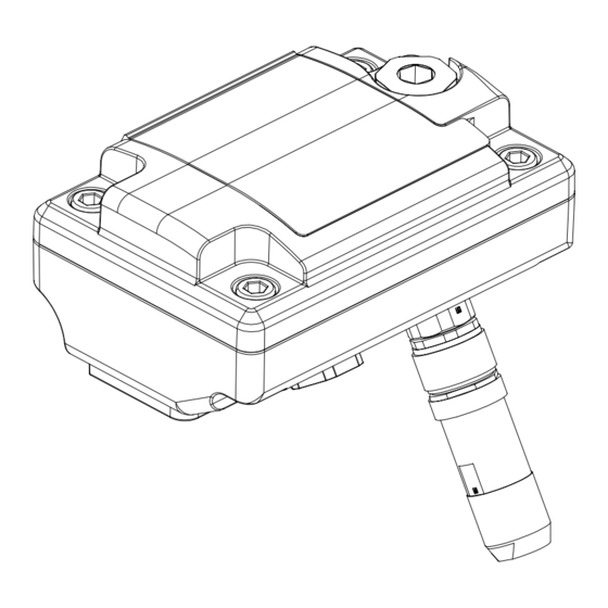
- Page 13 SCREW M4X6 TC GROWER Ø 4 FLAT CABLE MV800 PCB Housing in painted aluminum Housing in AISI 304 JB RAW Housing in AISI 304 JB POLISHED PG9 PLUG CABLE GLAND PG11 5 POLES CONNECTOR COMPLETE OF PLUG ISOIL MAN_MV800_EN_IT_IS_R04_1.02.XXXX 9 di 52...
-
Page 14: Electrical Connections
ELECTRICAL CONNECTIONS Version with cable 1 (+) POWER SUPPLY 2 (+) OUTPUT 1 / INPUT 3 (+) OUTPUT 2 (OPTIONAL) 4 (+) 4-20mA max load: 500Ω OUTPUT (OPTIONAL) 5 (-) POWER SUPPLY / OUTPUTS / INPUT 6 SHIELD (CONNECT TO GROUND) PIN 5-6 TO BE CONNECT TO THE GROUND Version with connector 1 (+) POWER SUPPLY... -
Page 15: Power Supply
‰ Ensure that the component complies with the requirements of the standard for electrical safety distance. ‰ Check chemical compatibility of materials used in the connection security systems in order to minimize electrochemical corrosion. ISOIL MAN_MV800_EN_IT_IS_R04_1.02.XXXX 11 di 52... -
Page 16: Outputs Wiring
OUTPUTS WIRING DIGITAL OUTPUTS 2 (Out1) ‰ Opto-insulated output 3 (Out2) ‰ Maximum switching voltage: 30V ‰ Maximum switching current: 100mA @ 25 °C ‰ Maximum saturation voltage between collector and emitter @100mA: 1.2V ‰ Maximum switching frequency (load on the collector or emitter, RL=470, VOUT=24V ): 1250Hz... -
Page 17: Data Transmission
The direct exposure of the converter to the solar rays, could damage the liquid crystal display. No display pages are provided. EMPTY PIPE WARNING ALARM WARNING PROCESS ALARM DATA m³/h TRANSMISSION gal/min m³ FLOW DIRECTION ACTIVE FLOW RATE FLOW RATE UNIT m³/h OF MEASURE gal/min m³ TOTALIZER UNIT OF MEASURE ISOIL MAN_MV800_EN_IT_IS_R04_1.02.XXXX 13 di 52... -
Page 18: Access To The Configuration Menu
ACCESS TO THE CONFIGURATION MENU You can access the device configuration menu only by MCP interface. MCP is a software that can be installed on Microsoft Windows® and allows you to set all the functions of the converter and customize the menu. To use the MCP interface, see the user manual . - Page 19 Flow speed % full scale Flow rate graph Flow rate value Flow rate trend Alarms list page Partial net totalizer Total net totalizer Reverse total totalizer Direct total totalizer Reverse partial totalizer Direct partial totalizer ISOIL MAN_MV800_EN_IT_IS_R04_1.02.XXXX 15 di 52...
- Page 20 MEANING OF FLAGS ON MCP INTERFACE FLAG DESCRIPTION EMPTY PIPE FILE UPLOAD FILE DOWNLOAD FLOW RATE SIMULATION (FLASHING) CALIBRATION (FLASHING) GENERIC ALARM (FLASHING) SIGNAL ERROR EXCITATION ERROR MIN FLOW ALARM MAX FLOW ALARM VIDEO TERMINAL CONNECTED FLOW RATE OVERFLOW PULSE 1 OVERFLOW PULSE 2 OVERFLOW MAN_MV800_EN_IT_IS_R04_1.02.XXXX...
-
Page 21: Quick Start Menu
POS. 9.8 see page 23. The quick start menu is only displayed by MCP interface. Access to all functions See programming functions section ISOIL MAN_MV800_EN_IT_IS_R04_1.02.XXXX 17 di 52... - Page 22 CONVERTER ACCESS CODE The access for programming the instrument is regulated by six access levels logically grouped. Every level is protected by a different code. ‰ Access Levels 1-2-3-4 Freely programmable by user Access Code Set : Menu 13 System The CODE is inserted by keyboard or MCP interface.
- Page 23 2 2 3 7 Press the enter button to confirm the changed value Press the esc key to exit from to the “quick start menu” and return to the main page 2 2 3 9 Main Page ISOIL MAN_MV800_EN_IT_IS_R04_1.02.XXXX 19 di 52...
- Page 24 EXAMPLE: modifying the full scale value from 4.0 L/s to 5.0dm3/s, from the “Main Menu” (quick start menu enabled) Press enter key to access in the Use the right-left arrow keys to select the “Quick Start menu” character and the up-down arrow key to assign the numeric value of the access code Press the enter key to confirm the access code Select the Main Menu function with the arrow...
-
Page 25: Functions Menu
T e m p . u n i t ° C 2.14 Mass units enabling M a s s u n i t s 2.15 Specific gravity coefficient S g = k g / d m 3 1 . 0 0 0 0 ISOIL MAN_MV800_EN_IT_IS_R04_1.02.XXXX 21 di 52... - Page 26 The physical display provides the following units of measure: l/s, m /h, gal/mln, m³, gal. Other units available are selectable and visible only by MCP. If you choice one of this unit of measure, it will not be displayed on the physical display, but will be visible only its numeric value. S C A L E S Full scale flow rate for range 1 F S 1 g / s...
- Page 27 Save sensor factory default val. Save Sens . f. def 11.8 Save converter factory default val. Save Conv . f. def 11.9 Internal circuit calibration C a l i b r a t i o n ISOIL MAN_MV800_EN_IT_IS_R04_1.02.XXXX 23 di 52...
- Page 28 D I A G N O S T I C 12.1 Self test diagnostic function S e l f t e s t 12.2 Sensor verify diagnostic function S e n s . v e r i f y 12.3 Flow rate simulation enabling F l o w s i m .
-
Page 29: Functions Description
Function shown on device display MCP command acronym The following picture describes where to find the name of the MCP functions in MCP-software. More info see MCP manual. Line editor for the insertion and execution of MCP commands. ISOIL MAN_MV800_EN_IT_IS_R04_1.02.XXXX 25 di 52... - Page 30 MENU 1 - SENSOR (POS. 1.1) Sensor MODeL [S. model xxx] [SMODL] Enter the first two characters of the serial number of the sensor as on the sensor label. (POS. 1.2) LIning MAterial Type [Lining= UNSPEC.] [LIMAT] Flow sensor lining material type. (PFA; PU-TDI; ALON; PEEK; HR; PP; PA-11; PTFE-HT; PTFE) (POS.
- Page 31 Delay before generating error. This function is useful to prevent unexpected lock to zero of measure caused by sporadic events (empty pipe, excitation error, signal error) (POS. 1.22) Automatic Sensor VeriFy Enable [Sens. verify= OFF] [ASVFE] Enable the Automatic sensor verification (see BIV optional function). ISOIL MAN_MV800_EN_IT_IS_R04_1.02.XXXX 27 di 52...
- Page 32 (POS. 1.23) CoeFFicient KL [KL=XX +/- XXXXXXXXX] [SETKL] Linearization coefficient for negative flow, reserved to the service. This command is only showed if SMODL = 000. (POS. 1.24) SET KJ value [Zero point cal.] [SETKJ] This feature appears only when the process conditions are as follow: ‰...
-
Page 33: Menu 2 - Units
This function changes the values unit of measure on POS. 2.10 see page 21. It is visualized on visualization pages. (POS. 2.10) Totalizer Total Negative Unit of measure [T- unit= m³] [TTNUM] Setting total reverse totalizer unit of measure. This function visualized on visualization pages. ISOIL MAN_MV800_EN_IT_IS_R04_1.02.XXXX 29 di 52... - Page 34 (POS. 2.11) Totalizer Partial Negative Unit of measure Type [P- unit= METRIC] [TPNUT] This function is active with POS. 9.5 see page 23 , enable. Setting partial reverse totalizer unit of measure type: metric or not metric (Imperial units). This function changes the values unit of measure on POS.
- Page 35 If the sensor is insertion type and the diameter is zero, the only possible unit is m/s if the flow rate were chosen metric units, else f/s for the unit of measurement non metric. ISOIL MAN_MV800_EN_IT_IS_R04_1.02.XXXX...
- Page 36 (POS. 3.3-3.5) Output Pulse 1-2 [Pls1-2= dm³ x.xxxxx] [OP1PV-OP2PV] Pls1 and Pls2 are activated with POS. 7.1 see page 23 and POS. 7.2 see page 23 enabled and set to pulse value. This function allows the user to set a signal (a pulse) to be given from the converter when a defined amount of volume has passed through the sensor.
-
Page 37: Menu 4 - Measure
FILTERS flow rate. Increasing the parameter of damping >>>> >>>> Damping= from 0.2s to 1000s FLOW RATE MEASURE increases the stability of the measurement. TIME (Sec) ISOIL MAN_MV800_EN_IT_IS_R04_1.02.XXXX 33 di 52... - Page 38 (POS. 4.2) Measure Filter CUt-off Threshold [Cut-off=% xxx] [MFCUT] Setting the low flow cutoff threshold. This function is useful to avoid increasing of the totalizers that flows close to zero, due to the electrical noises from tiny movements of liquid (due for example to vibrations of the pipe). The allowed range for this function is 0-25% of full scale set.
-
Page 39: Menu 5 - Alarms
‰ 0% Hz * frequency * 100% f.s.: normal working range; ‰ 100% f.s. < frequency * 110% f.s.: overflow, measure above the 100% of the f.s.; ‰ 115% f.s. * frequency * 125% f.s.: hardware alarm condition. ISOIL MAN_MV800_EN_IT_IS_R04_1.02.XXXX 35 di 52... -
Page 40: Menu 7 - Outputs
MENU 7 - OUTPUTS (POS. 7.1) OUTput 1 Function [Out1=XXXXXX] [OUT1F] Function choice corresponding to digital Output 1. The functions are listed in the table below. (POS. 7.2) OUTput 2 Function [Out2=XXXXXX] [OUT2F] Function choice corresponding to digital Output 2. The functions are listed in the table below. FUNCTIONS FOR OUTPUTS 1 AND 2 ‰... - Page 41 +100% F.S. +110% F.S. zero zero (POS. 7.4) Analog Output 1 Full Scale [A1S= dm/s x.xxxx] [AO1FS] It allows to set the full scale value for analog output 1 independently from the main scale of the instrument. ISOIL MAN_MV800_EN_IT_IS_R04_1.02.XXXX 37 di 52...
-
Page 42: Menu 9 - Display
MENU 9 - DISPLAY (POS. 9.1) Layout LANGuage [Language= GB/...] [LLANG] Choice of the language. There are 2 languages available: GB = English, IT = Italian, TR = Turkish, PL = Polish, DE = German, FR = French, PT = Portuguese, ES = Spanish. (POS. - Page 43 4. S. Freq. -> Menu Sensor 1 To check the calibration status, active or inactive, type the command MCP Calic? and check as follows: CALIC = 1 calibration in progress CALIC = 0 calibration terminated ISOIL MAN_MV800_EN_IT_IS_R04_1.02.XXXX 39 di 52...
-
Page 44: Menu 12 - Diagnostic
MENU 12 - DIAGNOSTIC (POS. 12.1) AutoTeSt Immediate Command [Self Test] [ATSIC] Meter auto-test function. This function stops the normal functions of the meter and performs a complete test cycle on the measure input circuits and on the excitation generator. To activate this function, after selecting it, push the Enter key, at the question: “CONFIRM EXEC.?”... - Page 45 This function displays graphs of input Z, C. current, C. Volt, C.Load, Input 1, Input 2, Input1-Input 2, Analog to Digital Converter. (POS. 12.7) Generic sensor set [ Gen.sens. set ] NO MCP COMMAND Automatic finding of a parameter set for a generic sensor. ISOIL MAN_MV800_EN_IT_IS_R04_1.02.XXXX 41 di 52...
- Page 46 (POS. 12.8) MODel and Software Version [Firmware info] MODSV Firmware info version/revision (POS. 12.9) SeRial NUMber [ S/N= xxxxxx ] [SRNUM?] View Board serial number. (read only) (POS. 12.10) Total WorKing TiMe [ WT= xxxx: xx: xx: xx ] [TWKTM?] View Total working time instrument.
- Page 47 DEVICE IP PC/SERVER ADDRESS (POS. 13.11) CoeFFicient KT [KF=X.XXXXX] [CFFKT] Gain correction coefficient (calculated automatically) (POS. 13.12) CoeFFicient KS [KF=X.XXXXX] [CFFKS] Correction coefficient constant flowmeter (POS. 13.13) CoeFFicient KR [KR=X.XXXXX] [CFFKR] Correction coefficient constant flowmeter ISOIL MAN_MV800_EN_IT_IS_R04_1.02.XXXX 43 di 52...
- Page 48 DIGITAL ANALOG CONVERTER (Correction Parameters)(13.17-18-19-20) The diagram shows how the DAC4-4-20mA max load:500Ω parameters are setup. The DAC1 value corresponds to 4 mA corresponding to a zero flow rate, while the value of 20mA corresponds to a 100% of the flow rate. (POS.
- Page 49 View compact list of all available converter functions. Functions Menu SELection [MCP ONLY] [FMSEL] Select menu for functions list ConFiguration LiST [MCP ONLY] [CFLST] Configuration parameter list. The list with the status / values of the converter parameters ISOIL MAN_MV800_EN_IT_IS_R04_1.02.XXXX 45 di 52...
- Page 50 Volume Totalizer Total Positive Set [MCP ONLY] [VTTPS] This function allows to set the value of total positive totalizer. Volume Totalizer Partial Positive Set [MCP ONLY] [VTPPS] This function allows to set the value of partial positive totalizer. Volume Totalizer Total Negative Set [MCP ONLY] [VTTNS] This function allows to set the value of total negative totalizer.
- Page 51 Volume Totalizer Total Positive Overflow [MCP ONLY] [VTTPO] Totalizer T+ number of overflows Volume Totalizer Partial Positive Overflow [MCP ONLY] [VTPPO] Totalizer P+ number of overflows Volume Totalizer Total Negative Overflow [MCP ONLY] [VTTNO] Totalizer T- number of overflows ISOIL MAN_MV800_EN_IT_IS_R04_1.02.XXXX 47 di 52...
- Page 52 Volume Totalizer Partial Negative Overflow [MCP ONLY] [VTPNO] Totalizer P- number of overflows CPU TemPerature [MCP ONLY] [CPUTP] CPU temperature LiQuid VELocity [MCP ONLY] [LQVEL] Liquid velocity (m/s) AVeraGe process data Samples Number [MCP ONLY] [AVGSN] Number of samples for averaged values ALARM status [MCP ONLY] [ALARM]...
- Page 53 [017] CALIBR.ERROR Calibration Error Contact the service [018] SYSTEM FREQ. System Freq. Error Contact the service [019] B.DATA NOT INIT Uninitialized data system Contact the service [020] FL.SENSOR Flow rate sensor error Contact the service ERROR ISOIL MAN_MV800_EN_IT_IS_R04_1.02.XXXX 49 di 52...
- Page 54 MANUAL REVIEWS REVIEW DATE DESCRIPTION MV800_EN_IT_R0_1.00.0 09/10/2017 First edition MV800_EN_IT_R1_1.00.0 02/11/2017 Insert ground reference on electrical wiring MV800_EN_IT_R2_1.02.0 06/07/2020 Software upgrade and graphics changes Changes on functions descriptions, tightening torque added, 4-20 MV800_EN_IT_R3_1.02.0 08/04/2021 output graph added, graphic update MAN_MV800_EN_IT_IS_ 07/10/2021 changes to data relating to digital output...
- Page 55 At the end of its lifetime, this product shall be disposed of in full compliance with the environmental regulations of the state in which it is located. ISOIL MAN_MV800_EN_IT_IS_R04_1.02.XXXX 51 di 52...
- Page 56 ISOIL INDUSTRIA S.p.A. HEAD OFFICE SERVICE Via Fratelli Gracchi, 27 service@isoil.it 20092 Cinisello Balsamo (MI) Tel +39 02 66027.1 Fax +39 02 6123202 vendite@isoil.it If you want to find the complete list of our distributors access at the following link: http://www.isoil.it/en...
Need help?
Do you have a question about the ISOMAG MV800 and is the answer not in the manual?
Questions and answers