Table of Contents
Advertisement
Quick Links
Advertisement
Table of Contents

Related Manuals for ISOIL ISOMAG CS8100


Summary of Contents for ISOIL ISOMAG CS8100
- Page 1 OPERATING AND MAINTENANCE MANUAL CS8100 8100_EN_IT_IS_R0_1.0X...
- Page 2 Release number: 8100_EN_IT_IS_R0_1.0X - The characters of file name in bolt type indicate the software version which the manual refers to; it is visualized at the instrument start up, or by specific function on DIAGNOSTIC menu. The reproduction of this manual and any supplied software is strictly forbidden.
-
Page 3: Table Of Contents
INDEX SAFETY INFORMATION ________________________________________________________________ 1 SAFETY CONVENTION _________________________________________________________________ 2 ENVIRONMENTAL USE CONDITIONS ______________________________________________________ 3 ELECTRIC CHARACTERISTICS ___________________________________________________________ 3 DATA PLATE _________________________________________________________________________ 3 OVERALL DIMENSIONS ________________________________________________________________ 4 SHREWDNESS AND PRECAUTIONS _______________________________________________________ 5 TIGHTENING TORQUE _________________________________________________________________ 6 OUTPUT WITH CONNETCTOR ____________________________________________________________ 7 ELECTRICAL CONNECTIONS ____________________________________________________________ 7 OUTPUT WITH CABLE__________________________________________________________________ 7 OUTPUTS WIRING ____________________________________________________________________ 8... -
Page 4: Safety Information
If you are unclear on anything in these Operating Instructions, you must call the ISOIL service. The Operating Instructions provide detailed information about the instrument. ‰ The flow meter should only be installed after having verified technical data provided in this operating instructions and on the data plate. -
Page 5: Safety Convention
SAFETY CONVENTION DANGER ELECTRIC SHOCK WARNING PRECAUTIONS ATTENTION 8100_EN_IT_IS_R0_1.0X 2 di 45... -
Page 6: Electric Characteristics
ELECTRIC CHARACTERISTICS Converter classification: class I, IP67/IP68 for noryl housing, installation category (overvoltage) II, rated pollution degree 2. Power supply voltage Power min10 / max30V ‰ Voltage variations must not exceed ±10% of the nominal one. ‰ Output insulated up to 500V. ‰... -
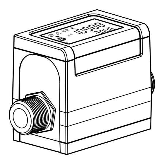
Page 7: Overall Dimensions
OVERALL DIMENSIONS ØD FITTINGS 1/2” GAS UNI338/NPT 3/4” GAS UNI338/NPT FITTINGS SOCKET FOR USB ACCESS (PROGRAMMING PORT) 5 POLES PLUG (available only on connector version) Ø D CABLEGLAND PG7 5 POLES CABLE VERSION 5 POLES CONNECTOR VERSION 8100_EN_IT_IS_R0_1.0X 4 di 45... -
Page 8: Shrewdness And Precautions
SHREWDNESS AND PRECAUTIONS Per installazioni verticali è preferibile il flusso ascendente. Per installazioni verticali con moto discendente In vertical installations an ascending flow is preferable. For vertical installations with descending flow direction contact the manufacturer contattare la fabbrica For installations in long pipe lines, please use anti vibration joints Per installazioni su lunghe tratte di condotte inserire dei giunti anti vibranti ANTIVIBRATION LONG PIPE... -
Page 9: Tightening Torque
TIGHTENING TORQUE ‰ Tightening torque: 20Nm ‰ Do not apply tension on the threaded connections when installing the flowmeter in the pipe line 8100_EN_IT_IS_R0_1.0X 6 di 45... -
Page 10: Output With Connetctor
ELECTRICAL CONNECTIONS OUTPUT WITH CONNETCTOR 1 (+) POWER SUPPLY 2 (+) OUTPUT 1 3 (+) OUTPUT 2 (OPTIONAL) 4 (+) 4-20mA max load: 500 Ω OUTPUT (OPTIONAL) 5 (-) POWER SUPPLY / OUTPUTS PIN 5 TO BE CONNECT TO THE GROUND OUTPUT WITH CABLE 1 (+) POWER SUPPLY 2 (+) OUTPUT 1... -
Page 11: Outputs Wiring
OUTPUTS WIRING DIGITAL OUTPUTS 2 (out1) 3 (out2) ‰ Maximum switching voltage:: 30VDC ‰ Maximum switching current:: 50mA 5 (-) ANALOG OUTPUT +24V INTERNAL ‰ Opto-insulated output ‰ The maximum load depends on the supply voltage and the values are as follows: 4 (+) 1000 ohm @30Vdc 800 ohm @24Vdc... -
Page 12: Flow Direction
The direct exposure of the converter to the solar rays, could damage the liquid crystal display. The visualization pages can be change according to instrument’s setup. m³/h gal/min m³ EMPTY PIPE WARNING ALARM WARNING PROCESS ALLARM DATA TRASMISSION FLOW DIRECTION ACTIVE FLOW RATE FLOW RATE MEASURE UNIT m³/h... -
Page 13: User Interface
U S E R I N T E R F A C E You can access the drive configuration menu only by MCP interface for CS8100. It is a software that can be installed on Microsoft Windows® and allows you to set all the functions of the converter and customize the menu. - Page 14 START VISUALIZATION PAGES ON MCP INTERFACE Electrode 2 resistance Electrode 1 resistance Video term. connected Flow speed % full scale Flow rate graph Flow rate value Flow rate trend Alarms list page Partial net totalizer Total net totalizer Reverse total totalizer Direct total totalizer Reverse partial totalizer Direct partial totalizer...
-
Page 15: Meaning Of Flags On Mcp Interface
MEANING OF FLAGS ON MCP INTERFACE FLAG DESCRIPTION EMPTY PIPE FILE UPLOAD FILE DOWNLOAD FLOW RATE SIMULATION (FLASHING) CALIBRATION (FLASHING) GENERIC ALARM (FLASHING) GENERAL ALARM ONLY ON PHYSICAL DISPLAY (FLASHING) SIGNAL ERROR EXCITATION ERROR MIN FLOW ALARM MAX FLOW ALARM VIDEO TERMINAL CONNECTED FLOW RATE OVERFLOW PULSE 1 OVERFLOW... -
Page 16: Flow Rate And Totalizer Visualization
FLOW RATE AND TOTALIZER VISUALIZATION m³/h gal/min m³ The CS8100 can show a 5 digits display on flow rate field value; this mean the maximum and minimum flow rate values that can be shown on display are: METRIC Measure Units Minimum Maximum 0.0267... -
Page 17: Access Code Set : Menu 13 System
CONVERTER ACCESS CODE The access for programming the instrument is regulated by six access levels logically grouped. Every level is protected by a different code. Access Level 1-2-3-4-5-6 Freely programmable by user 13 S CCESS ySTEM The CODE is Settable by MCP interface. Depending on the level of access different display functions will be visible. - Page 18 The following example shows how to change the Full scale by Quick Start menu; the second illustrates how to change the function by the Main menu. EXAMPLE: modifying the full scale value from 4L/s to 5L/s, from the “Quick start menu” Press enter key to access in the Use the right-left arrow keys to select the character and “Quick Start menu”...
- Page 19 EXAMPLE: modifying the full scale value from 4l/s to 5l/s, from the “Main Menu” (quick start menu enabled) Press enter key to access in the Use the right-left arrow keys to select the “Quick Start menu” character and the up-down arrow key to assign the numeric value of the access code Press the enter key to confirm the access code Select the Main Menu function with the arrow keys...
-
Page 20: Functions Menu
FUNCTIONS MENU The main menu is selected from the Quick start menu by pressing enter in your key board and entering the access code. Note: Functions in grey here below are displayed only with other functions active, or with optional modules. Sensors model: Enter the first two characters of the serial number of the sensor Type of measure units for sensor parameter: metric or imperial Calibration data of sensor... - Page 21 Measure filter Low flow zero threshold: 0-25% of full scale value Automatic calibration verify Maximum value alarm set for direct flow rate Maximum value alarm set for reverse flow rate Minimum value alarm set for direct flow rate Minimum value alarm set for reverse flow rate Hysteresis threshold set for the minimum and maximum flow rate alarms Current output value in case of failure Frequency output value in case of alarms...
- Page 22 11.1 Execute immediate reset of total direct totalizer 11.2 Execute immediate reset of partial direct totalizer 11.3 Execute immediate reset of total reverse totalizer 11.4 Execute immediate reset of partial reverse totalizer 11.5 Load sensor factory default 11.6 Load converter factory default 11.7 Save sensor factory default values 11.8...
-
Page 23: Functions Description
FUNCTIONS DESCRIPTION Find bellow a description of the menu rows. Menu visualized on the converter (from 1 to 13) MENU 1 - SENSOR Sensor Model (POS. 1.1) [S. model xxx] [SMODL] Access level MCP command Convert request1 Synthetic description of the function The following picture describes where to find the name of the MCP functions in MCP-software. -
Page 24: Menu 1 - Sensor
MENU 1 - SENSOR Sensor model (POS. 1.1) [S. model xxx] [SMODL] Enter the first two characters of the serial number of the sensor as on the sensor label. Unit type (POS. 1.2) [U.type= METRIC] [SUTYP] Select type of measure unit of sensor’s parameter. Values metric or imperial (inch). (POS. - Page 25 Coefficient KL (POS. 1.14) [KL=XX +/- XXXXXXXXX] [SETKL] Linearization coefficient for negative flow, reserved to the service. This command is only showed if SMODL = 000. Signal error delay (POS. 1.15) [S.err.delay=m xxx] [SEALT] Delay before generating error. This function is useful to prevent unexpected lock to zero of measure caused by sporadic events (empty pipe, excitation error, signal error) MENU 1 - SENSOR: ONLY MCP FUNCTIONS Coefficient KZ...
-
Page 26: Menu 2 - Units
MENU 2 - UNITS WARNING: The totalizer value is updated and changed depending on the setting of unit value. The scale change may cause accuracy loss depending of rounding up. For example, if T +=0,234 liters with 3 decimals, it become T +=0.001 m³ losing 0.234 liters in rounding up. Flow rate unit of m. - Page 27 Part. reverse unit of m. type (POS. 2.10)Total. [P- unit= METRIC] [TPNUT] This function is active with POS.9.5 see page 18, enable. Setting partial reverse totalizer measure unit type: metric or not metric (Imperial units). This function changes the values measure unit on POS.2.11 see page 17 It is visualized on visualization pages.
-
Page 28: Menu 3 - Scale
MENU 3 - SCALE Flow Rate Full Scale 1 (POS. 3.1) [FS1= l/s xxxx.x] [FRFS1] The full scale is used to indicate to the maximum meter’s flow rate. The full scale should be chosen carefully as it’s parameters are used for several other parameters.There are two fields to fill in order to set this parameter, from left to right: 1) measure unit, 2) numeric value. -
Page 29: Menu 4 - Measure
MENU 4 - MEASURE Damping (POS. 4.1) [Damping=OFF/SMART/(TIME)] [MFDMP] This section of manual is extremely important because the correct setting of the filters allows to obtain a proper response of the instrument to the measured flow rate and the specific requirements of use; as a general rule, consider that, starting from Damping = OFF (no filter applied to the measure), successive values, introduce increasing damping. - Page 30 Cut-off threshold (POS. 4.2) [Cut-off=% xxx] [MFCUT] Setting the low flow cutoff threshold. This function is useful to avoid that flows close to zero, due to the electrical noises from tiny movements of liquid (due for example to vibrations of the pipe) which cause an increasing of the totalizers.
-
Page 31: Menu 5 - Alarms
MENU 5 - ALARMS Maximum direct flow rate threshold (POS. 5.1) [Max. thr+=% XXX] [FRAXP] Maximum value alarm set for direct flow rate set. When the flow rate value exceeds such a threshold, then an alarm message is generated. The value of this parameter is expressed as percentage of the full scale value and may be set from 0 to 125%. - Page 32 Frequency output value in case of failure (POS. 5.7) [Hz V.alarm=%XXX] [OFACV] This function is active with POS. 7.1-7.2 enable to ( FREQ.+, FREQ.-, FREQ.±) To set the frequency value assigned to the on/off output in one or more of the following failure cases: Empty pipe;...
-
Page 33: Menu 7 - Outputs
MENU 7 - OUTPUTS Output 1 function selection (POS. 7.1) [Out1=XXXXXX] [OUT1F] Function choice corresponding to digital Output 1. The functions are listed in the table below. Output 2 function selection (POS. 7.2) [Out2=XXXXXX] [OUT2F] Function choice corresponding to digital Output 2. The functions are listed in the table below. FUNCTIONS FOR OUTPUTS 1 AND 2 ‰... - Page 34 CURRENT VALUES IN mA ASSOCIATE TO THE % FULL SCALE VALUE REVERSE FLOW POSSIBLE FIELD ZERO DIRECT FLOW VALUE VALUE ≤-110% -100% +100% ≥+110% Out.mA = 0 ÷ 20 + Out.mA = 0 ÷ 22 + Out.mA = 4 ÷ 20 + *Out.mA = 4 ÷...
-
Page 35: Menu 9 - Display
MENU 9 - DISPLAY Language for all msn (POS. 9.1) [Language= ITA/EN] [LLANG] Choice of the language. There are 2 languages available: EN = english, IT = Italian. Display Contrast (POS. 9.2) Contrast (POS. 9.2) [Contrast= [Contrast= [DCNTR] Display contrast set. The contrast can change according to the room temperature. The allowed range is from 0 to 9. -
Page 36: Menu 11 - Function
MENU 11 - FUNCTION The following functions are activated by first pressing the “ENTER” and then the “ESC” when the screen appears “confirm” to start the function. Total direct totalizer reset (POS. 11.1) [T+ RESET= ON] [VTTPR] Reset total direct totalizer for direct flow rate (+) Partial direct totalizer reset (POS. -
Page 37: Menu 12 - Diagnostic
MENU 12 - DIAGNOSTIC Self Test Diagnostic (POS. 12.1) [Self Test] [ATSIC] Meter auto-test function. This function stops the normal functions of the meter and performs a complete test cycle on the measure input circuits and on the excitation generator. To activate this function, after select it, push key Enter, at the question: “CONFIRM EXEC.?”... - Page 38 (POS. 12.6) Display graphs [ Display graphs ] NO MCP COMMAND This function displays graphs of input Z, C. current, C. Volt, C.Load, Input 1, Input 2, Input1-Input 2, Analog to Digital Converter. Firmware info (POS. 12.7) [Firmware info] MODSV Firmware info version/revision Board Serial Number...
-
Page 39: Menu 13 - System
MENU 13 - SYSTEM (POS. 13.1-2-3-4-5-6) Access level n° code [Ln xxxxxxxx] [L1ACD]-> [L6ACD] This function enables or disables, for each access level code, the main menu functions. Each level unlocks the functionality of the lower level. (Function “13.7 Restricted access level”... - Page 40 DIGITAL ANALOG CONVERTER (Correction Parameters)(13.17-18-19-20) The diagram shows how the DAC 4-20mA max load: 500 Ω parameters are setup. The DAC1 value corresponds to 4 mA corresponding to a zero flow rate, while the value of 20mA corresponds to a 100% of the flow rate. (POS.
- Page 41 Quick Start All Functions Selection [MCP ONLY] [QSLST] Select ALL function converter for quick start menu. Function enable Status LiST [MCP ONLY] [FSLST] List enable status of functions Access CODE [MCP ONLY] [ACODE] Input the right access code Exemple set quick start menù...
- Page 42 Volume Totalizer Total Positive Set [MCP ONLY] [VTTPS] Totaliz.T+ value set Volume Totalizer Partial Positive Set [MCP ONLY] [VTPPS] Totaliz.P+ value set Volume Totalizer Total Negative Set [MCP ONLY] [VTTNS] Totaliz.T- value set Volume Totalizer Partial Negative Set [MCP ONLY] [VTPNS] Totaliz.P- value set Volume Total Positive Overflow Set...
-
Page 43: Menu 15 - Process Data (Only Mcp)
MENU 15 - PROCESS DATA (ONLY MCP) OUTput 1 Set [MCP ONLY] [OUT1S] Set value for digital output 1 OUTput 2 Set [MCP ONLY] [OUT2S] Set value for digital output 2 Flow Rate Full Scale in chosen Units [MCP ONLY] [FRFSU] F.rate f.scale in chosen units Flow Rate Value PerCentage... - Page 44 CPU temperature [MCP ONLY] [CPUTP] CPU temperature LiQuid VELocity [MCP ONLY] [LQVEL] Liquid velocity AVeraGe process data Samples Number [MCP ONLY] [AVGSN] N.of samples for averaged values ALARM status [MCP ONLY] [ALARM] Active alarm(s) status Main power status [MCP ONLY] [MPWRS] Status of main power supply INput RESistance...
-
Page 45: Alarm Messages (Causes And Actions To Be Taken)
ALARM MESSAGES (CAUSES AND ACTIONS TO BE TAKEN) MESSAGGIO CAUSE ACTION TO TAKE NO ALARMS All works regularly [000] SYSTEM RESTART [001] SYSTEM RESTART Internal PS Fail Contact the service [005] F-RAM ERROR Error writing / reading Flash-RAM Contact the service The excitation of the sensor coils resulting [006] EXCITATION ERROR Check the connecting cables to the sensor. -
Page 46: Manual Reviews
MANUAL REVIEWS REVIEW DATE DESCRIPTION 8100_EN_IT_R0_1.00.0 22/12/2017 First edition 8100_EN_IT_IS_R0_1.0X 43 di 45... - Page 47 At the end of its lifetime, this product shall be disposed of in full compliance with the environmental regulations of the state in which it is located. 8100_EN_IT_IS_R0_1.0X 44 di 45...
- Page 48 ISOIL INDUSTRIA S.p.A. HEAD OFFICE SERVICE Via Fratelli Gracchi, 27 isomagservice@isoil.it 20092 Cinisello Balsamo (MI) Tel +39 02 66027.1 Fax +39 02 6123202 vendite@isoil.it If you want to find the complete list of our distributors access at the following link: http://www.isoil.com/u_vendita.asp...
Need help?
Do you have a question about the ISOMAG CS8100 and is the answer not in the manual?
Questions and answers