
Subscribe to Our Youtube Channel
Related Manuals for ISOIL Isoflux IFX-F100


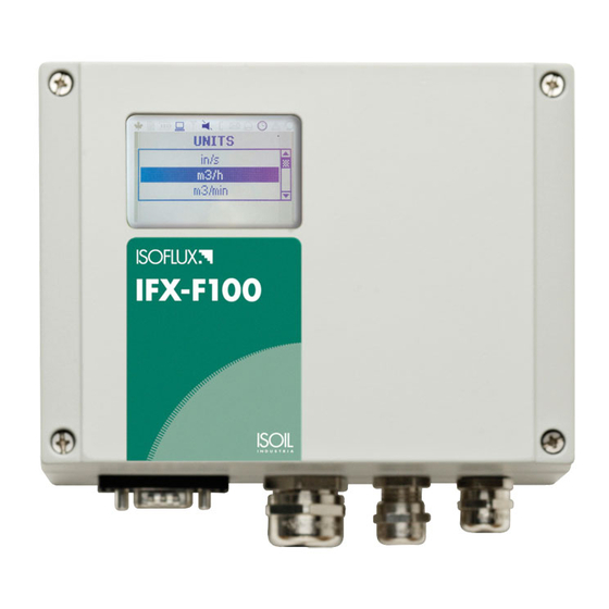
Summary of Contents for ISOIL Isoflux IFX-F100
- Page 1 IFX-F100 Ultrasonic clamp-on Flow Transmitter Flow_Transmitter_IFX-F100_EN_2018_March_Rev.00...
-
Page 2: Table Of Contents
IFX-F100 Operating Instructions Index Page Safety instructions ................4 Symbols used in these operating instructions ........4 Safety instructions ................5 Introduction ..................6 How to order ..................7 Installation .................... 8 Unpacking and storage ..............8 3.1.1 Unpacking ................8 3.1.2 Storage .................. - Page 3 IFX-F100 Table of Contents 4.4.4 Datalogger ................25 Commissioning ................... 25 Menu structure ................25 Diagnostics ..................31 Display settings ................31 5.3.1 Main PV ................. 31 Output settings ................31 5.4.1 Serial interface RS 232 ............31 5.4.2 Serial interface RS 485 / Modbus RTU ........31 5.4.3 HART compatible output ............
-
Page 4: Safety Instructions
Safety instructions Symbols used in these operating instructions Danger This symbol represents an immediate hazardous situation which could result in a serious injury, death or damage to the equipment. Where this symbol is shown, do not use the equipment further unless you have fully understood the nature of the hazard and have taken the required precautions. -
Page 5: Safety Instructions
• Install the equipment and cabling securely and safely according to the relevant regulations. • If the product does not operate normally, please refer to the ser- vice and troubleshooting instructions, or contact Isoil Industria for help. Flow_Transmitter_IFX-F100_EN_2018_March_Rev.0... -
Page 6: Introduction
Introduction Clamp-on The IFX-F100 is a hand-held, battery operated ultrasonic flowmeter employ- transit-time flowmeter ing clamp-on sensors for the measurement of liquids in full, enclosed pipes. Flow measurements can be undertaken without interruption of the process or interference with the integrity of the pipeline. The clamp-on sensors are attached to the outside of the pipes. -
Page 7: How To Order
IFX-F100 User Manual How to order Flow_Transmitter_IFX-F100_EN_2018_March_Rev.0... -
Page 8: Installation
Installation Unpacking and storage Unpacking 3.1.1 Care should be taken when opening the box containing the flowmeter, any markings or warnings shown on the packaging should be observed prior to opening. The following steps should then be taken: • Unpack the flowmeter in a dry area; •... -
Page 9: Clamp-On Sensor Installation
IFX-F100 User Manual Clamp-on sensor installation The correct selection of the sensor location is crucial for achieving reliable measurements and a high accuracy. Measurement must take place on a pipe in which sound can propagate (see Acoustic Propagation) and in which a rotationally symmetrical flow profile is fully developed (see Straight Pipe Lengths). -
Page 10: Installation Location
Installation location Select an installation location following the recommendations in Table 1 and try to avoid measuring: • in the vicinity of deformations and defects of the pipe, • near welding seams, • where deposits could be building up in the pipe. For a horizontal pipe: Select a location where the transducers can be mounted on the side of the pipe, so that the sound waves emitted by the transducers propagate horizontally in the pipe. - Page 11 IFX-F100 User Manual Disturbance source: 90°-elbow Inlet Outlet L 10 D L 5 D Disturbance source: 2 x 90°-elbows in one plane Inlet Outlet L 25 D L 5 D Disturbance source: 2 x 90°-elbows in different planes Inlet Outlet L ...
-
Page 12: Pipe Preparation
Disturbance source: valve Inlet Outlet L 40 D L 10 D Disturbance source: pump Inlet L 50 D Table 2: Recommended distances from disturbance sources Pipe preparation • Clean dirt and dust from around the area of the pipework where the sensors are to be placed;... - Page 13 IFX-F100 User Manual Illustration 3: Clamp-on sensor mounting configurations and sensor spacing Transducer The transducer separation distance A is measured from the inside edges of separation distance the sensor heads as shown in illustration 3. It is automatically calculated by the flowmeter based on the parameter entries for pipe outside diameter, wall thickness, lining material and thickness, medium, process temperature, the sensor type and the selected number of signal passes.
-
Page 14: Flowmeter Installation
Flowmeter installation 3.6.1 Outline dimensions The IFX-F100 is a wall mounted device and can be installed using suitable screws and wall plugs according to the following drawings. Flowmeter outline dimensions Drilling aid for all mounting Make sure that the ambient temperature is within the -10 ... 60 °C operating temperature range specified for the flowmeter unit. -
Page 15: Electrical Connections
IFX-F100 User Manual 3.6.2 Electrical connections Please note that in order to supply the unit with MAINS POWER, the equipment must Electrical wiring be protected by suitably sized switches and circuit breakers. 100 ... 240 V AC, 50/60 Hz 10 W 9 ... -
Page 16: Clamp-On Sensor Mounting
Clamp-on sensor mounting Before the sensors can be mounted Sensor mounting • the installation location should have been determined, • a sensor mounting method should be chosen, • the flowmeter must be mechanically and electrically installed, • the sensors must be connected to the flowmeter. Depending on which sensor mounting method is being used, the clamp on sensors are either mounted on the same side of the pipe (Reflection Mode) or on opposite sides of the pipe (Diagonal Mode). -
Page 17: Sensor Pipe Mounting Configurations
IFX-F100 User Manual 3.7.1 Sensor pipe mounting configurations Illustration 4: Sensor pipe mounting configurations 3.7.2 Acoustic coupling gel In order to obtain acoustical contact between the pipe and the sensors, apply a bead of acoustic coupling gel lengthwise down the centre of the contact area of the sensors. -
Page 18: Sensor Mounting With Tension Straps
The sensor separation distance is automatically calculated by the flowmeter based on the parameter entries for pipe outside diameter, wall thickness, lin- ing material and thickness, medium, process temperature, the sensor type and the selected number of signal passes. 3.7.4 Sensor mounting with tension straps Illustration 6: Metallic mounting straps •... -
Page 19: Operation
IFX-F100 User Manual • Ensure that the narrower side of the clip is above and inside the wider side and that the two sides of the clip do not come into con- tact while tightening, as this will prevent the strap from being cor- rectly tensioned. -
Page 20: Display Functions
Backlight on/off ESCape menu item Abort entry without saving, escape measurement mode ENTer menu item Confirm entry with saving or move through menu structure Table 3: Keyboard function 4.2.2 Display functions Menu header Display icons Display line 2 Display line 1 Date, Time Display icons Display icon... -
Page 21: Quick Setup Wizard
IFX-F100 User Manual Error recorded in error log No error detected Serial output switched on Serial output switched off "L", "T" or "LT" Displays whether flow is laminar, turbulent or mixed Quick setup wizard The quick setup wizard allows for a speedy setup of the most important pa- Quick start wizard rameters in order to achieve successful measurements in the shortest pos- sible time:... - Page 22 Choose pipe material using cursor keys and pressing <ENTER>. Enter outside pipe diameter using alphanumeri- cal keys and confirm by pressing <ENTER>. Use key <UP> as character backspace clear to correct for data entry errors. If 0 is entered, an additional screen appears that allows entering the pipe circumference.
- Page 23 IFX-F100 User Manual Use cursor keys to select Write Flowmeter. Confirm by pressing <ENTER>. The programmer will send setup parameters to the flowmeter. Use cursor keys to select Sensor Positioning. Confirm by pressing <ENTER>. Use cursor keys to select Start Measurement. Confirm by pressing <ENTER>.
-
Page 24: Measurements
Measurements 4.4.1 Main process value (PV) display Measurement is started using the Quick Setup Wizard. Once all the param- eters are programmed, any subsequent power-on sequences will bring up the main PV display immediately. Display screen Operation The main process value can be changed in the menu structure. -
Page 25: Diagnostic Displays
IFX-F100 User Manual 4.4.2 Diagnostic displays Diagnostic screens Display screen Operation Line 1 shows the amplifier gain. Line 2 displays the signal strength. Line 3 indicates the noise. Change to more diagnostic displays by pressing <NEXT>. 4.4.3 Totalisers The totaliser displays will only be shown when the totalisers are activated. Totalisers Display screen Operation... - Page 26 K4N,K4L,K4E,K4Ex,K4P, K0, M, Q, Special Middle (main Select from list where available ↑↓ displayed) m/s, f/s, in/s, m3/h, m3/min, m3/s, l/h, l/min, l/s, Units USgal/h, USgal/min, USgal/s, bbl/d, bbl/h, bbl/min, g/s, t/h, kg/h, kg/min, m3, l, Usgal, bbl, g, t, kg, W, kW, MW, J, kJ, MJ, Signal (dB), noise (dB), SNR (dB), C m/s (measured sound speed), CU (housing...
- Page 27 IFX-F100 User Manual Off, On, Reset + (positive total), Reset – (negative total) Reset Both Start Measurement Sensor type Indication of sensor type and serial number if au- tomatically detected, otherwise select from list ↑↓ As Setup Wizard Sensor fre- SP1, only for special, unrecognised sensors quency Wedge angle...
- Page 28 Damping Reduces fluctuations in the display output 1 ... 255 s Metric / Imp Use metric or imperial units for entered data In/Output Type Select from list ↑↓ Current out Source Channel 1 System Units Select from list ↑↓ Min Value Min.
- Page 29 IFX-F100 User Manual Alarm – PV alarm switch Math – Calculated value alarm switch Fault – Allocated to system failures, see error re- port list On Point Value of PV at which the relay energises when in alarm mode Off Point Value of PV at which the relay de-energises when in alarm m ode Current In...
- Page 30 User Identifier Example: Pump P3A 9 character string Tag No. Example: 1FT-3011 9 character string Test Installation Control system simulation: A cyclic repetition of in- creasing flow velocity across the measureable range. All configured outputs respond as if this was a measured change in flow. Yes, No Display Display screen test routine...
-
Page 31: Diagnostics
IFX-F100 User Manual 9600, 19200, 57600,115200 Parity Select from list ↑↓ None Even (Default) Table 5: Firmware menu structure Diagnostics Diagnostic screens, where specified, can be viewed directly during measure- ment using the programmer or through the menu structure (screen only). Display settings The main Process Value (PV) is the primary measurement data. -
Page 32: Hart Compatible Output
Wiring Setup Please refer to customer support. Operation Please refer to customer support. 5.4.3 HART compatible output The KF150 can also be configured with an optional module which responds to output commands conforming to the HART protocol. Please refer to customer support for further information. -
Page 33: Analogue Voltage Output 0 - 10 V
IFX-F100 User Manual 5.4.5 Analogue voltage output 0 – 10 v Voltage outputs may be assigned to process values in the “mode” section of the output menu. The outputs can be programmed and scaled within the menu structure. Wiring Electrical Galvanically isolated from main electronics and from other I/O's. -
Page 34: Input Configuration
Wiring Electrical Form A (SPDT-NO and NC) contacts characteris- Width 3...990 ms. tics U=48 V, Imax=250 mA.Galvanically isolated from main electronics and from other I/O's. Mode: Alarm, fault, totaliser (programmable). 1 Form A (SPST-NO) contacts. 1 Form A (SPST-NC) contacts. Width 3...990 ms. -
Page 35: Sound Velocity Measurement (Svm)
IFX-F100 User Manual If a heat quantity unit is specified for the Process Value, the KF100 will prompt the user for the Specific Heat Capacity of the medium in J/g/K (for example 4.186 J/g/K for water). This may also be entered in the System\Calculation sub-menu. The In/Output menu will then allow the user to select the temperature input source;... -
Page 36: Maintenance
• This means that Isoil can only service this device if it is accompanied by a Return Authorization Number (RAN) confirming that the device is safe to handle. - Page 37 IFX-F100 User Manual Error list Error message Group Description Error handling USB INIT FAIL Hardware Internal board communi- Power on/off, otherwise cation error call customer support NO SERIAL NO. Hardware Failed to read from FRAM Call customer support NO VERSION NO. Hardware Failed to read from FRAM Call customer support PARA READ FAIL...
-
Page 38: Data Download Difficulties
SENSOR COU- Application Weak sensor coupling, Recouple sensors, PLING ERR low SNR check installation, re- duce number of passes, look for other location, call customer support Table 6: Error messages Data download difficulties If difficulties are encountered downloading the logger data: - Check that the flowmeter is switched on and not in measurement ●... -
Page 39: Technical Data
IFX-F100 User Manual Technical data Sound Speed* Shear Wave (at 25 ºC) Material ft/s Steel, 1% Carbon, hardened 3,150 10,335 Carbon Steel 3,230 10,598 Mild Steel 3,235 10,614 Steel, 1% Carbon 3,220 10,565 302 Stainless Steel 3,120 10,236 303 Stainless Steel 3,120 10,236 304 Stainless Steel... - Page 40 All data given at 25 ºC (77 ºF) unless otherwise stated Change Kinematic Viscosity Sound Speed v/ºC Chemical Specific Substance ft/s m/s/ºC mm x10-6 ft Formula Gravity Acetic anhydride (CH3CO)2O 1.082 (20 ºC) 1,180 3,871.4 0.769 8.274 Acetic acid, anhydride (CH3CO)2O 1.082 (20 ºC) 1,180...
- Page 41 IFX-F100 User Manual 1,328.7 (- Methane 0.162 (-89 ºC) 17.5 (-89 ºC) 128 ºF) Methanol CH4O 0.791 (20 ºC) 1,076 3,530.2 0.695 7.478 Methyl acetate C3H6O2 0.934 1,211 3,973.1 0.407 4.379 Methyl alcohol CH4O 0.791 1,076 3,530.2 0.695 7.478 1,328 4,357 (68 Methyl benzene C7H8...
- Page 42 1,170 3,838.6 Tetrachloroethane C2H2Cl4 1553 (20 ºC) 1.19 12.804 (20 ºC) (68 ºF) Tetrachloro-ethene C2Cl4 1.632 1,036 3,399 Tetrachloro-Methane CCl4 1.595 (20 ºC) 3,038.1 0.607 6.531 Tetrafluoro-methane 875.24 (- 2,871.5 (- 1.75 (-150 ºC) 6.61 (Freon 14) 150 ºC) 283 ºF) 1,328 4,357 (68 Toluene...
- Page 43 IFX-F100 User Manual 95.0 1519 4984 96.8 1521 4984 98.6 1523 4990 100.4 1525 4997 102.2 1527 5010 104.0 1528 5013 105.8 1530 5020 107.6 1532 5026 109.4 1534 5033 111.2 1535 5036 113.0 1536 5040 114.8 1538 5046 116.6 1538 5049 118.4...
- Page 44 192.2 1551 5089 194.0 1550 5086 195.8 1549 5082 197.6 1549 5082 199.4 1548 5079 201.2 1547 5076 203.0 1547 5076 204.8 1546 5072 206.6 1545 5069 208.4 1544 5066 210.2 1543 5063 212.0 1543 5063 220.0 1538 5046 230.0 1532 5026 240.0...
-
Page 45: Specification
IFX-F100 User Manual Specification General Measuring principle : Ultrasonic time difference correlation principle Flow velocity range : 0.01 ... 25 m/s Resolution : 0.25 mm/s Repeatability : 0.15 % of measured value ± 0.015 m/s Accuracy : ± 1 ... 3 % of measured value depending on application, ±... - Page 46 Process inputs / Process Outputs (maximum of four per instrument) Inputs Temperature : PT 100, three or four-wire circuit, measuring range - 50 ... 400 °C, resolution 0.1K, accuracy ±0.2 K Current : 0 ... 20 mA active or 4 ... 20 mA passive, U = 30 V, Ri = 50 Ohm, accuracy 0.1 % of MV Outputs Current : 0/4 ...
-
Page 47: Ce Declaration Of Conformity
/dichiariamo sotto la nostra responsabilità che i seguenti prodotti: Product model/Modello: Ultrasonic flowmeter/Misuratore di portata ad ultrasuoni: Isoflux IFX-F100, IFX-P200, IFX-P210 and associated trasducers/ e i trasduttori associati are in conformity with the EEC directives /sono conformi alle seguenti direttive europee:... - Page 48 For EU Customers only - WEEE Marking. Marking of electrical and electronic equipment in accordance with Directive 2012/19/EU This symbol on the product indicates that it will not be treated as household waste. It must be handed over to the applicable take-back scheme for the recycling of electrical and electronic equipment.
- Page 49 ISOIL INDUSTRIA S.p.A HEAD OFFICE SERVICE Via Fratelli Gracchi, 27 isomagservice@isoil.it 20092 Cinisello Balsamo (MI) Tel +39 02 66027.1 Fax 039 026123202 sales@isoil.it If you want to find the complete list of our distributors access at the following link: http://isoil.com/u_vendita.asp...
Need help?
Do you have a question about the Isoflux IFX-F100 and is the answer not in the manual?
Questions and answers