Table of Contents
Advertisement
Quick Links
Advertisement
Table of Contents

Subscribe to Our Youtube Channel
Related Manuals for Woodward SPM-D10/YB


Summary of Contents for Woodward SPM-D10/YB
- Page 1 37134D SPM-D10/YB Synchronizing Unit Manual from Version 4.0xx Manual 37134D...
- Page 2 Provides other helpful information that does not fall under the warning or caution categories. Woodward reserves the right to update any portion of this publication at any time. Information provided by Woodward is believed to be correct and reliable. However, Woodward assumes no responsibility unless otherwise expressly undertaken.
-
Page 3: Table Of Contents
Manual 37134D SPM-D10/YB - Synchronizing Unit Revision History Rev. Date Editor Changes NEW 03-10-17 Release 04-11-24 Correction: Wide-range power supply (wiring diagram, power supply) 05-05-10 Improved: Controller setting description, wide-range power supply, technical data; language review 06-03-08 Minor corrections; Package harmonization Voltage range changed from “90 to 250 Vac/dc”... - Page 4 Product Service Options ......................... 45 Returning Equipment For Repair ......................45 Packing A Control ......................... 46 Return Authorization Number RAN ....................46 Replacement Parts ..........................46 How To Contact Woodward ........................47 Engineering Services ..........................48 Technical Assistance ..........................49 Page 4/50 © Woodward...
- Page 5 Manual 37134D SPM-D10/YB - Synchronizing Unit Illustrations and Tables Illustrations Figure 3-1: Wiring diagram SPM-D10/YB ..........................9 Figure 3-2: Wiring diagram SPM-D10/NYB ..........................10 Figure 3-3: Reference point ............................... 11 Figure 3-4: Power supply ................................11 Figure 3-5: Measuring inputs - mains - system U1 ........................12 Figure 3-6: Measuring inputs - generator - system U2 .......................
-
Page 6: Chapter 1. General Information
Manual 37134D SPM-D10/YB - Synchronizing Unit Chapter 1. General Information SPM-D10/YB is a three-phase synchronizing unit with expanded dead bus start functionality. The following functions can be realized by using the appropriate discrete inputs: Synchronization Synch-check Dead bus start The SPM-D starts as a standard unit that may have additional functions added with each package. -
Page 7: Chapter 2. Electrostatic Discharge Awareness
WARNING To prevent damage to electronic components caused by improper handling, read and observe the pre- cautions in Woodward manual 82715, Guide for Handling and Protection of Electronic Controls, Printed Circuit Boards, and Modules. © Woodward Page 7/50... -
Page 8: Chapter 3. Installation
Manual 37134D SPM-D10/YB - Synchronizing Unit Chapter 3. Installation CAUTION A circuit breaker must be provided near to the unit and in a position easily accessible to the operator. This must also bear a sign identifying it as an isolating switch for the unit. -
Page 9: Wiring Diagram
Manual 37134D SPM-D10/YB - Synchronizing Unit Wiring Diagram ≡≡≡≡≡≡≡≡≡≡≡≡≡≡≡≡≡≡≡≡≡≡≡≡≡ SPM-D10/YB * At the terminal 21/51 "Voltage L2 / N" lower the following as to be applied: - voltage measuring "1 phase L-N" = zero-conductor N SPEED raise - voltage measuring "1 phase L-L" = conductor L2 Three-position controller - voltage measuring "3 phase"... -
Page 10: Spm-D10/Nyb
Manual 37134D SPM-D10/YB - Synchronizing Unit SPM-D10/NYB Figure 3-2: Wiring diagram SPM-D10/NYB Page 10/50 © Woodward... -
Page 11: Reference Point
Manual 37134D SPM-D10/YB - Synchronizing Unit Reference Point ≡≡≡≡≡≡≡≡≡≡≡≡≡≡≡≡≡≡≡≡≡≡≡≡≡ Reference point Figure 3-3: Reference point Terminal Description Reference point: Neutral point of the three-phase system (3Ph4W) or neutral terminal of the voltage transformer (Measuring reference Sold.lug point); with three-conductor systems (3Ph3W), do not connect Power Supply ≡≡≡≡≡≡≡≡≡≡≡≡≡≡≡≡≡≡≡≡≡≡≡≡≡... -
Page 12: Measuring Inputs
Manual 37134D SPM-D10/YB - Synchronizing Unit Measuring Inputs ≡≡≡≡≡≡≡≡≡≡≡≡≡≡≡≡≡≡≡≡≡≡≡≡≡ Mains/System U1 Voltage L2/N System U1 Figure 3-5: Measuring inputs - mains - system U1 Terminal Measurement Description Voltage L1 2.5 mm² Direct or measuring Voltage L2 / N 2.5 mm²... -
Page 13: Discrete Inputs
Manual 37134D SPM-D10/YB - Synchronizing Unit Discrete Inputs ≡≡≡≡≡≡≡≡≡≡≡≡≡≡≡≡≡≡≡≡≡≡≡≡≡ CAUTION Please note that the maximum voltages which may be applied at the discrete inputs are defined as fol- lows. Voltages higher than those specified will damage the hardware! Maximum input range: +/-18 to 250 Vac. -
Page 14: Relay Outputs
Manual 37134D SPM-D10/YB - Synchronizing Unit Relay Outputs ≡≡≡≡≡≡≡≡≡≡≡≡≡≡≡≡≡≡≡≡≡≡≡≡≡ max. 250 Vac Relay output external device Figure 3-9: Relay outputs - control output #1 (CB operation) Root Switched Description Synchronizing pulse; Command: close CB 2.5 mm² max. 250 Vac Relay output... -
Page 15: Chapter 4. Description Of Functions
Manual 37134D SPM-D10/YB - Synchronizing Unit Chapter 4. Description of Functions Functionality ≡≡≡≡≡≡≡≡≡≡≡≡≡≡≡≡≡≡≡≡≡≡≡≡≡ Table of Functions NOTE The following table is only valid, if terminal 54 is not set Input signal Operating condition No-load control Synchronizing No-load control Synchronizing Dead bus start No-load control 0: "OFF"... -
Page 16: Control Inputs
Manual 37134D SPM-D10/YB - Synchronizing Unit Control Inputs ≡≡≡≡≡≡≡≡≡≡≡≡≡≡≡≡≡≡≡≡≡≡≡≡≡ Release CB Enabling for the operation of the power circuit breaker. Terminal 3 In order to enable synchronization or a dead bus start, this input must be en- ergized. Reply: CB is open... -
Page 17: Operating Conditions
Manual 37134D SPM-D10/YB - Synchronizing Unit Operating Conditions ≡≡≡≡≡≡≡≡≡≡≡≡≡≡≡≡≡≡≡≡≡≡≡≡≡ No Load Control With the relays of the three-position controller and speed switching appropriately, voltage and frequency of the system U2 are adjusted to the configurable set point values. (Also see chapter "Table of Functions" starting on page 15). -
Page 18: Dead Bus Start (Asynchronous Add-On)
Manual 37134D SPM-D10/YB - Synchronizing Unit Dead Bus Start (Asynchronous Add-On) Output of an add-on order for the power circuit breaker without synchronization, if the following conditions are fulfilled: The dead bus start function is in principle activated by configuration ... -
Page 19: Control Outputs
Manual 37134D SPM-D10/YB - Synchronizing Unit Control Outputs ≡≡≡≡≡≡≡≡≡≡≡≡≡≡≡≡≡≡≡≡≡≡≡≡≡ Synchronizing pulse: Through this relay, the CB receives the order to add-on. In normal operation, close CB the contact assembly in the synchronous point only closes for the configured Terminals 14/15 time of the add-on pulse. -
Page 20: Chapter 5. Display And Operating Elements
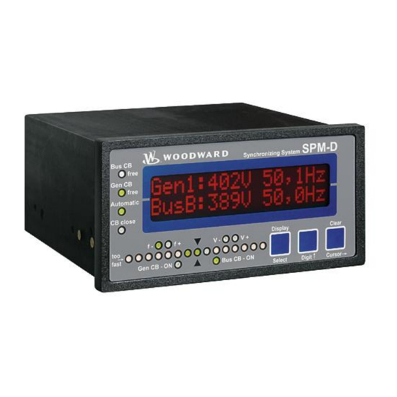
Manual 37134D SPM-D10/YB - Synchronizing Unit Chapter 5. Display and Operating Elements The foil of the front plate is made of coated plastics. All keys have been designed as touch-sensitive membrane switch elements. The display is a LC-display, consisting of 2 rows each with 16 characters, which are indirectly il- luminated red. -
Page 21: Brief Explanation Of The Leds And Push Buttons
Manual 37134D SPM-D10/YB - Synchronizing Unit Brief Explanation of the LEDs and Push Buttons ≡≡≡≡≡≡≡≡≡≡≡≡≡≡≡≡≡≡≡≡≡≡≡≡≡ LEDs No. Description Function Bus CB Free Non-functional Gen CB Free Enable CB Automatic Automatic mode CB close Close command to the CB issued Synchroscope... -
Page 22: Leds
Manual 37134D SPM-D10/YB - Synchronizing Unit LEDs ≡≡≡≡≡≡≡≡≡≡≡≡≡≡≡≡≡≡≡≡≡≡≡≡≡ Bus CB Free Enable mains circuit breaker here: non-functional Color: green NOTE: This LED is non-functional, as this control is only designed to oper- ate one circuit breaker. Gen CB Free Enable power circuit breaker Color: green The LED "Gen CB Free"... - Page 23 Manual 37134D SPM-D10/YB - Synchronizing Unit Decrease frequency governor output Color: yellow The "f-" LED indicates if the unit is outputting a pulse to decrease the fre- quency. The "f-" LED illuminates when the relay "speed lower" is energized. Increase frequency governor output Color: yellow The "f+"...
-
Page 24: Push Buttons
Manual 37134D SPM-D10/YB - Synchronizing Unit Push Buttons ≡≡≡≡≡≡≡≡≡≡≡≡≡≡≡≡≡≡≡≡≡≡≡≡≡ Configuration may be performed by manually inputting the desired set points utilizing the pushbuttons and the LC display. In order to facilitate configuring the parameters, the push buttons have been enabled with an AUTOROLL function. -
Page 25: Lc Display
Manual 37134D SPM-D10/YB - Synchronizing Unit LC Display ≡≡≡≡≡≡≡≡≡≡≡≡≡≡≡≡≡≡≡≡≡≡≡≡≡ LC-Display LC display The two-line LC display outputs corresponding text messages and values de- pending on the mode that the SPM-D is operating. In the configuration mode, the monitoring parameters may be changed. When the SPM-D is in the auto- matic mode, the measured values are displayed. -
Page 26: Chapter 6. Configuration
Manual 37134D SPM-D10/YB - Synchronizing Unit Chapter 6. Configuration CAUTION Please note that configuration only should be done when the system is not in operation. NOTE Please note the parameter list located in the Appendix C of this manual. The configuration mode is initiated by pressing the "Digit" and "Cursor" pushbuttons simultaneously. The control is advanced through the various parameters by pressing the "Select"... -
Page 27: General
Manual 37134D SPM-D10/YB - Synchronizing Unit General ≡≡≡≡≡≡≡≡≡≡≡≡≡≡≡≡≡≡≡≡≡≡≡≡≡ Service Indication Service indication ON/OFF Service display? ON ....The subsequent screens are indicated. The screens of the service indi- cation are intended to help the user start-up the unit. OFF ....The screens of the service indication are not indicated. -
Page 28: Sealing
Manual 37134D SPM-D10/YB - Synchronizing Unit Sealing NOTE If a protection against the modification of setting values is not required, we recommend not to activate the sealing function, parameter to "OFF". If sealing should be necessary however, we recommend to activate it only after the system has been completely installed! ... -
Page 29: Figure 6-1: Sealing - Sequence Diagram
Manual 37134D SPM-D10/YB - Synchronizing Unit Figure 6-1: Sealing - sequence diagram © Woodward Page 29/50... -
Page 30: Configure Basic Settings
Manual 37134D SPM-D10/YB - Synchronizing Unit Configure Basic Settings ≡≡≡≡≡≡≡≡≡≡≡≡≡≡≡≡≡≡≡≡≡≡≡≡≡ WARNING The following values must be entered correctly to ensure proper monitoring of the generator. Failure to do so may lead to incorrect measuring of parameters resulting in damage to or destruction of the gen-... -
Page 31: Configure Controller
Manual 37134D SPM-D10/YB - Synchronizing Unit Configure Controller ≡≡≡≡≡≡≡≡≡≡≡≡≡≡≡≡≡≡≡≡≡≡≡≡≡ Entering values in the subsequent screens will result in changes to the dynamics of the controller. CAUTION The following values must be entered correctly to ensure proper operation of the generator. Failure to... -
Page 32: Frequency Controller
Manual 37134D SPM-D10/YB - Synchronizing Unit Frequency Controller Frequency controller ON/OFF Parameter 11 Freq. controller ON ....The generator frequency is controlled by the SPM-D. The generator frequency is controlled in various manners depending on the task (no load / isolated operation / synchronization). The subsequent screens of this function are displayed. -
Page 33: Voltage Controller
Manual 37134D SPM-D10/YB - Synchronizing Unit Voltage Controller Voltage controller ON/OFF Parameter 19 Volt. controller ON ....Generator voltage control is performed by the SPM-D. Depending on the task (no-load control/ synchronization), the generator voltage is controlled in different ways. The subsequent screens of this function are displayed. -
Page 34: Synchronization
Manual 37134D SPM-D10/YB - Synchronizing Unit Synchronization ≡≡≡≡≡≡≡≡≡≡≡≡≡≡≡≡≡≡≡≡≡≡≡≡≡ Configure Synchronization NOTE The unit detects if the systems have a different rotating field and prevents a CB closure. Synchronous functions ON/OFF Parameter 24 Synchron. Gen. ON ....The generator frequency and voltage is adjusted to the permissible dif- ferential ranges for the busbar/mains prior to issuing a connect com- mand. -
Page 35: Dead Bus Start
Manual 37134D SPM-D10/YB - Synchronizing Unit Dead Bus Start Asynchronous switching ON/OFF Parameter 31 Gen. circ.break. ON ....Asynchronous switching of the power circuit breaker is admitted. The Asyn.connect ON subsequent screens of this function are displayed. OFF ....Asynchronous switching is not admitted, and the subsequent screens of this function are not displayed. -
Page 36: Relay Output 16-17
Manual 37134D SPM-D10/YB - Synchronizing Unit Relay Output 16-17 " Message: Connect 2" The method of functioning of the relay "Message: Connect 2" depends on the Terminal 16/17 setting of the screen "Rel. connect 2". Relay function connect 2 OFF /asynch.only/ synchr. only/ syn/asyn. -
Page 37: Synchronizing Time Monitoring
Manual 37134D SPM-D10/YB - Synchronizing Unit Synchronizing Time Monitoring Synchronizing time monitoring ON/OFF Parameter 40 Sync.time contr. ON ....No time monitoring for the synchronization is carried out. As soon as the synchronization starts, a time counter is started simultaneously. If the power circuit breaker is not closed after the pre-set time, a warning is released "Synchron. -
Page 38: Chapter 7. Commissioning
Manual 37134D SPM-D10/YB - Synchronizing Unit Chapter 7. Commissioning DANGER - HIGH VOLTAGE When commissioning the unit, please observe all safety rules that apply to the handling of live equip- ment. Ensure that you know how to provide first aid in the event of an uncontrolled release of energy and that you know where the first aid kit and the nearest telephone are. - Page 39 Manual 37134D SPM-D10/YB - Synchronizing Unit Synchronizing the power circuit breaker: Open the power circuit breaker. b) Ensure the reference voltage that the system has to synchronize to is within the permissible limits. Energize terminal 3 "Enable CB". Configure the parameters of the governor.
-
Page 40: Figure 7-1: Dimensions
Manual 37134D SPM-D10/YB - Synchronizing Unit Appendix A. Dimensions Configuration port Configuration port Front view (without function) (without function) Back plate mount option (please order brackets P/N 8923-1023) Bottom view 108.8 Back view with connecting terminals 0 1 1 SPM-D10... - Page 41 Manual 37134D SPM-D10/YB - Synchronizing Unit Appendix B. Technical Data Measuring voltage ---------------------------------------------------------------------------------------------- Measuring voltage Rated value (V ) / ........[1] 66/115 Vac rated [4] 230/400 Vac Maximum value V (UL/cUL) ....[1] max. 150 Vac Ph-Ph [4] max. 300 Vac Rated voltage V ..........
- Page 42 Manual 37134D SPM-D10/YB - Synchronizing Unit Housing ----------------------------------------------------------------------------------------------------------- - Type ....................APRANORM DIN 43 700 - Dimensions (W × H × D) .................144 × 72 × 122 mm - Front cutout (W×H) ..............138 [+1.0] × 67 [+0.7] mm - Wiring ................Screw-type terminals depending on plug connector 1.5 mm²...
- Page 43 Manual 37134D SPM-D10/YB - Synchronizing Unit Appendix C. List of Parameters Product number P/N _____________________________ Rev _______________________________ Version SPM-D10/YB __________________________________________________________ Project _____________________________________________________________________ Serial number S/N _______________ Date ______________________________ Parameter Default Adjustment range Customer settings Option 100/400V; 1/5 A setting CONFIGURE GENERAL PARAMETERS Software version 4.0xxx...
- Page 44 Manual 37134D SPM-D10/YB - Synchronizing Unit Parameter Standard Adjustment range Customer settings Option 100/400V; 1/5 A setting CONFIGURE SYNCHRONIZATION Synchron. Gen. on off on off ON/OFF Synchron. Gen. df max 0.02 to 0.49 Hz 0.18 Hz Synchron.
-
Page 45: Product Service Options
≡≡≡≡≡≡≡≡≡≡≡≡≡≡≡≡≡≡≡≡≡≡≡≡≡ If a control (or any part of an electronic control) is to be returned to Woodward for repair, please contact Wood- ward in advance to obtain a Return Authorization Number. When shipping the unit(s), attach a tag with the fol- lowing information: ... -
Page 46: Packing A Control
Stuttgart [+49 (0) 711 789 54-0]. They will help expedite the processing of your order through our distributors or local service facility. To expedite the repair process, contact Woodward in advance to obtain a Return Authoriza- tion Number, and arrange for issue of a purchase order for the unit(s) to be repaired. No work can be started until a purchase order is received. -
Page 47: How To Contact Woodward
For assistance outside Germany, call one of the following international Woodward facilities to obtain the address and phone number of the facility nearest your location where you will be able to get information and service. Please contact the Woodward Customer Service Department or consult our worldwide directory on Woodward’s website (www.woodward.com) for the name of your nearest Woodward distributor or service facility. -
Page 48: Engineering Services
Colorado, or from one of many worldwide Woodward offices or authorized distributors. Field engineers are expe- rienced on both Woodward products as well as on much of the non-Woodward equipment with which our prod- ucts interface. For field service engineering assistance, please contact us via our toll-free or local phone numbers, e-mail us, or use our website and reference field service. -
Page 49: Technical Assistance
Manual 37134D SPM-D10/YB - Synchronizing Unit Technical Assistance ≡≡≡≡≡≡≡≡≡≡≡≡≡≡≡≡≡≡≡≡≡≡≡≡≡ If you need to telephone for technical assistance, you will need to provide the following information. Please write it down here before phoning: Contact Your company ____________________________________________________ Your name _______________________________________________________ Phone number ____________________________________________________... - Page 50 Phone +49 (0) 711 789 54-510 Fax +49 (0) 711 789 54-101 stgt-info@woodward.com Homepage http://www.woodward.com Woodward has company-owned plants, subsidiaries, and branches, as well as authorized distributors and other authorized service and sales facilities throughout the world. Complete address/phone/fax/e-mail information for all locations is available on our website (www.woodward.com).
Need help?
Do you have a question about the SPM-D10/YB and is the answer not in the manual?
Questions and answers