
Related Manuals for Woodward SPM-D1145B/LSR


Summary of Contents for Woodward SPM-D1145B/LSR
- Page 1 37259E SPM-D11 Synchronizing Unit Manual from Software version 6.3xx Manual 37259E...
- Page 2 Provides other helpful information that does not fall under the warning or caution categories. Woodward reserves the right to update any portion of this publication at any time. Information provided by Woodward is believed to be correct and reliable. However, Woodward assumes no responsibility unless otherwise expressly undertaken.
-
Page 3: Table Of Contents
Closing the CB Without Synchronization (Dead Bus Start) ............26 Shutdown ............................. 27 Mains Parallel Operation ......................27 Load Sharing ..........................27 var Sharing ........................... 28 LED "Gen CB - ON" Flashes......................28 Control Outputs ............................29 Analog Controller Outputs ........................30 © Woodward Page 3/82... - Page 4 Product Service Options ........................77 Returning Equipment for Repair ......................77 Packing a Control ........................78 Return Authorization Number RAN ..................... 78 Replacement Parts ..........................78 How to contact Woodward ........................79 Engineering Services ..........................80 Technical Assistance ..........................81 Page 4/82 © Woodward...
- Page 5 Table 4-1: Operating conditions - Terminal 6 = "Enable control" .................... 20 Table 4-2: Operating conditions - Terminal 6 = "OFF" ......................21 Table 4-3: Operating conditions - status of measuring inputs and configuration ..............22 Table 4-4: Power set point modes ............................. 27 © Woodward Page 5/82...
-
Page 6: Chapter 1. General Information
[1] = 100 Vac [4] = 400 Vac Type Examples: • SPM-D1145B/LSR (LSR package with 400 Vac PT measuring inputs and ../5 A CT measuring inputs) • SPM-D1111B/LSXR (LSXR package with 100 Vac PT measuring inputs and ../1 A CT measuring inputs) Intended Use The control must only be operated for the uses described in this manual. -
Page 7: Chapter 2. Electrostatic Discharge Awareness
CAUTION To prevent damage to electronic components caused by improper handling, read and observe the pre- cautions in Woodward manual 82715, Guide for Handling and Protection of Electronic Controls, Printed Circuit Boards, and Modules. © Woodward Page 7/82... -
Page 8: Chapter 3. Installation
The following chart may be used to convert square millimeters [mm²] to AWG and vice versa: mm² mm² mm² mm² mm² mm² 0.05 0.38 600MCM 0.08 750MCM 0.14 0.75 300MCM 1000MCM 0.25 350MCM 0.34 500MCM Table 3-1: Conversion chart - wire size Page 8/82 © Woodward... -
Page 9: Wiring Diagram
N.C.: The relay opens if the function is triggered + Power supply (refer to label for actual rating V Reference point (terminal 29/30) Subject to technical modifications. 2006-01-26 | SPM-D11 Wiring Diagram spmd11ww-0406-ap.SKF Figure 3-1: Wiring diagram SPM-D11/LSR © Woodward Page 9/82... -
Page 10: Spm-D11/Lsxr
N.C.: The relay opens if the function is triggered + Power supply (refer to label for actual rating V Reference point (terminal 29/30) Subject to technical modifications. 2006-01-26 | SPM-D11 Wiring Diagram spmd11ww-0406-ap.SKF Figure 3-2: Wiring diagram SPM-D11/LSXR Page 10/82 © Woodward... -
Page 11: Reference Point
• = 24 Vdc = 12/24 Vdc • 24 Vdc 12/24 Vdc 24 Vdc / 12/24 Vdc Power supply 0 Vdc Figure 3-4: Power supply Terminal Description 2.5 mm² +24 Vdc +12/24Vdc 0 Vdc 2.5 mm² © Woodward Page 11/82... -
Page 12: Measuring Inputs
Generator voltage L2 2.5 mm² direct or Reference point: N-terminal of the low voltage Transformer system or star point of the voltage transducer ../100 V (measuring reference point); Solder.lug do not connect in delta connection installa- tions Page 12/82 © Woodward... -
Page 13: Current
If the generator load is always symmetrically, the current may also be measured in L2 or L3. This must be considered when configuring the SPM-D11 (refer to Current Transformer section on page 43). If there is a possibility that the load may be asymmetrical, the current must be measured in L1. © Woodward Page 13/82... -
Page 14: Discrete Inputs
Enable isolated operation / dead bus start 2.5 mm² Enable control or release power set point value 2 * 2.5 mm² NC (break) contact Reply: CB is open 2.5 mm² * refer to parameter Parameter 14 "Terminal 6" on page 44 Page 14/82 © Woodward... -
Page 15: Analog Inputs
SPM-D11s 2 1 0 2 1 0 2 1 0 SPM-D11 SPM-D11 SPM-D11 Analog output Analog output Analog output 0 to 4 Vdc 0 to 4 Vdc 0 to 4 Vdc Figure 3-10: Load sharing © Woodward Page 15/82... -
Page 16: Relay Outputs
Note: The relay is energized and closed when the function is fulfilled. Ready for operation 2.5 mm² N.C. functionality Root Switched Description Note: The relay will be de-energized and opens when the power limit is exceeded. Power limit 2.5 mm² Page 16/82 © Woodward... -
Page 17: Controller Outputs
Figure 3-13: Controller - SPM-D11/LSR - three-position controller Terminal Description common 2.5 mm² Speed/frequency controller raise 2.5 mm² Real power controller lower 2.5 mm² common 2.5 mm² Voltage controller raise 2.5 mm² Power factor controller lower 2.5 mm² © Woodward Page 17/82... -
Page 18: Spm-D11/Lsxr
250 Vac Relay output The relay has to be decoupled. Figure 3-14: Controller - SPM-D11/LSXR - three-position controller Terminal Description 2.5 mm² raise Speed / Frequency controller 2.5 mm² 2.5 mm² Voltage controller lower 2.5 mm² Page 18/82 © Woodward... -
Page 19: Figure 3-15: Controller - Spm-D11/Lsxr - Analog Controller Output - Speed/Frequency/Real Power
Figure 3-16: Controller - SPM-D11/LSXR - Analog controller output - Voltage/power factor Type Terminal Description 2.5 mm² 2.5 mm² Current 2.5 mm² Voltage controller Power factor cosphi controller 2.5 mm² 2.5 mm² Voltage 2.5 mm² © Woodward Page 19/82... -
Page 20: Chapter 4. Description Of Functions
Load/var sharing or Isolated operation Load/var sharing or isolated operation or shut down 0: "OFF" / 1: "ON" / x: Signal of no significance (0 or 1) Table 4-1: Operating conditions - Terminal 6 = "Enable control" Page 20/82 © Woodward... -
Page 21: Table 4-2: Operating Conditions - Terminal 6 = "Off
Load/var sharing or isolated operation Load/var sharing or isolated operation or shut down 0: "OFF" / 1: "ON" / x: Signal of no significance (0 or 1) Table 4-2: Operating conditions - Terminal 6 = "OFF" © Woodward Page 21/82... -
Page 22: Additional Conditions
Shut down - Parameter "Shut down ON" - for load sharing: Parameter "Load sharing ON" Load/var sharing control - for var sharing: Parameter "var sharing ON" Table 4-3: Operating conditions - status of measuring inputs and configuration Page 22/82 © Woodward... -
Page 23: Control Inputs
If several generators are released for dead bus start at the same time, it may happen that the generator circuit breakers close at the same time, which might cause serious damage to the generators! © Woodward Page 23/82... -
Page 24: Isolation Of The Power Supply From The Discrete Inputs
• Reference points connected with 0 V Jumper between terminal 7 and terminal 2 (0 V) • Reference point of the discrete inputs potential-free: Terminal 2: 0 V (supply voltage) Terminal 7: 0 V or N (control voltage) Page 24/82 © Woodward... -
Page 25: Operating Conditions
• The input "Reply CB is open" is energized The close command is issued without consideration of the inherent switching delay. In the phase-angle-zero- control mode, the analog input should be selected for the frequency controller. © Woodward Page 25/82... -
Page 26: Synch-Check
If several participants in a power pool are enabled to perform a dead bus start, an external interlock must ensure that it is not possible for two or more units to perform a dead bus start. Page 26/82 © Woodward... -
Page 27: Shutdown
(in reference to the relevant rated power) is subdivided equally amongst those gensets involved. Note – The frequency regulators of the generators must be suitably configured for parallel operation (i.e. droop operation mode) © Woodward Page 27/82... -
Page 28: Var Sharing
If the LED flashes, one must check to see whether the input on terminal 4 is wired correctly. If the terminal is wired correctly, there will be 0 V applied to the input when the power circuit breaker is closed. Page 28/82 © Woodward... -
Page 29: Control Outputs
Using this relay, it is possible for example to disconnect loads or activate further generators. © Woodward Page 29/82... -
Page 30: Analog Controller Outputs
: Period starting when the value of the control variable leaves the predefined tolerance range for sett the control variable following a step in the disturbance variable or reference input variable and ending when the value re-enters this range permanently. Page 30/82 © Woodward... - Page 31 There are various methods of setting a controller. The setting rules of Ziegler and Nichols are explained below (determination for abrupt disturbances on the system input); this setting method assumes a pure lag element con- nected in series with a first-order lag system. © Woodward Page 31/82...
-
Page 32: Figure 4-3: Step Response - Controller Set-Up
The lower the derivative-action time is is configured as 0.00 s, the D- configured, the higher the controller reaction is. If T component of the PID loop is disabled. Page 32/82 © Woodward... -
Page 33: Chapter 5. Display And Operating Elements
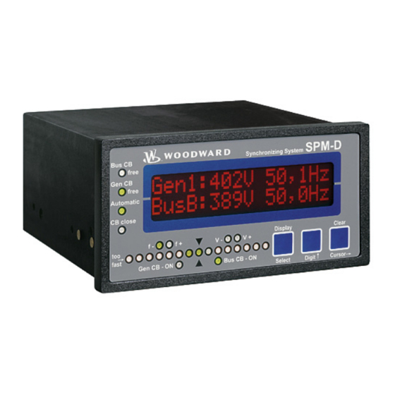
Contrast of the display is infinitely variable by a rotary potentiometer at the left side. SPM-D Synchronizing System Bus CB Free Gen CB Free Automatic CB close Gen CB - ON Bus CB - ON Figure 5-1: Front foil © Woodward Page 33/82... -
Page 34: Brief Explanation Of The Leds And Push Buttons
Non-functional Buttons No Description Function Display↓ Scroll display Select Confirm selection Digit↑ Increase digit Clear Acknowledge alarm Cursor→ Shift input position one digit to the right Others No Description Function LC-Display LC-Display Potentiometer Adjust LCD contrast Page 34/82 © Woodward... -
Page 35: Leds
→ left . If the LED's run from right to left, the generator frequency is too low, i. e., the generator or the variable bus frequency is too slow. © Woodward Page 35/82... - Page 36 (see also chapter "LED "Gen CB - ON" Flashes" on page 28). Bus CB – ON Mains power circuit breaker ON here: non-functional Color: green NOTE: This LED is non-functional, as this is a "One-power-circuit-breaker configuration". Page 36/82 © Woodward...
-
Page 37: Push Buttons
Configuration: Cursor→ - This button moves the cursor one position from left to right. When the cursor is under the last digit that may be changed, it may be moved to the first number of the value by pressing the "Cursor→" button again. © Woodward Page 37/82... -
Page 38: Lc Display
Synchronization time is exceeded Wirebreak P Wire break 0/4-20mA input for set point value set. Gen. underfrequency. Generator underfrequency Gen. overfrequency. Generator overfrequency Gen.undervoltage. Generator undervoltage Gen.overvoltage. Generator overvoltage Gen.overload. Generator overload Reverse/reduced load. Generator reverse-/-reduced load Page 38/82 © Woodward... -
Page 39: Chapter 6. Configuration
The desired language for the controller to operate in is set by this parameter. The screens (configuration and display screens) can be displayed either in German or English. Software version Software version x.xxxx Indicates the software version currently installed. © Woodward Page 39/82... -
Page 40: Password Protection
ON ....The password for code level 1 or 2 must be entered to access configu- ration. If a wrong code number was entered, the configuration will be blocked. OFF ....All users have direct access to all parameters, the pass code is not re- quired. Page 40/82 © Woodward... -
Page 41: Direct Configuration
PC - The baud rate of the LeoPC1 program must be set to 9600 Baud - The corresponding configuration file must be used (file name: "*.cfg") NO ....Configuration via the configuration plug is disabled. © Woodward Page 41/82... -
Page 42: Configure Basic Settings
Generator set point voltage [1] 50 to 125 V, [4] 50 to 440 V Parameter 8 Gen. voltage This value of the voltage specifies the set point of the generator voltage for no-load Set point 000V and isolated operation. Page 42/82 © Woodward... -
Page 43: Current Transformer
-060 -120 -180 Generator rated power [1] 100 to 9,999 kW; [4] 5 to 9,999 kW Parameter 12 Rated power Value of the generator rated power. Gen. = 0000kW © Woodward Page 43/82... -
Page 44: Configure Controller
PWM .... The frequency controller operates as a continuous controller with a pulse-width-modulated output signal and constant level. Note: The controller setting and the following screens differ, depending on which type of controller is selected here. Page 44/82 © Woodward... - Page 45 ON time periods. The optimum setting depends on the behavior of setting 'THREESTEP' only the system. If the gain is too low, the control action becomes slow. If the gain is configured too high, the result is excessive overshoot/undershoot of the desired val- © Woodward Page 45/82...
- Page 46 This parameter is the start point for the output signal when the frequency controller Init.state 000% parameter is configured as OFF. The percentage value relates to the range between only LSXR Package the minimum and maximum values that control unit can output (see below). with 'ANALOG' or 'PWM' setting Page 46/82 © Woodward...
- Page 47 'ANALOG' or 'PWM' setting the reset attempts to correct for any offset. If Tn is configured as 0.00 s, the I- component of the PID loop is disabled. Refer to "Analog Controller Outputs" on page 30. © Woodward Page 47/82...
-
Page 48: Voltage Controller
= 00V/s is used to alter the rate at which the controller follows the set point value. The more LSXR Package: rapidly the set point should change, the greater should be the value set here. setting 'THREESTEP' Page 48/82 © Woodward... - Page 49 10 to 0mA (5 to 0V) 5 to 0V 5 Vdc 0 Vdc 4.5V to -0.5V 4,5 to 0,5V 4,5 Vdc 0,5 Vdc 20 to 0mA (10 to 0V) 10 to 0V 10 Vdc 0 Vdc © Woodward Page 49/82...
- Page 50 This parameter defines how quickly with 'ANALOG' setting the reset attempts to correct for any offset. If Tn is configured as 0.00 s, the I- component of the PID loop is disabled. Refer to "Analog Controller Outputs" on page 30. Page 50/82 © Woodward...
-
Page 51: Power Factor Control
Set point ramp of the power factor controller 0.01 to 0.30 /s Parameter 53 Pow.fact.control The set point ramp determines how fast the power factor set point approaches its Ramp 0.00/s target value. The slope of the ramp is linear. © Woodward Page 51/82... - Page 52 The lower the derivative-action time is with 'ANALOG' setting configured, the higher the controller reaction is. If TV is configured as 0.00 s, the D-component of the PID loop is disabled. Refer to "Analog Controller Outputs" on page 30. Page 52/82 © Woodward...
-
Page 53: Real Power Controller
Refer to the Shutdown section on page 27 for more informa- tion). OFF ....If "enable GCB" is removed, the CB will not be opened in isolated operation. In parallel isolated operation the generator CB remains closed. © Woodward Page 53/82... - Page 54 The more rapidly the set point should change, the greater should be the value set here. This ramp will also be used to reduce the power with a Shutdown (refer to page 27). Page 54/82 © Woodward...
- Page 55 The lower the derivative-action time is with 'ANALOG' or 'PWM' setting configured, the higher the controller reaction is. If TV is configured as 0.00 s, the D-component of the PID loop is disabled. Refer to "Analog Controller Outputs" on page 30. © Woodward Page 55/82...
- Page 56 Generator power monitoring delay 0 to 600 s Parameter 82 Power monitoring To open the relay contact, the threshold hast to be exceeded continuously for the Delay time =000% time configured here. Page 56/82 © Woodward...
-
Page 57: Load/Var Sharing
Actual reactive power (without display) Analog signal -340 kW 85% of the rated power capacitive = negative reactive power 0 kW 2.5V 0% of the rated power no reactive power +340 kW 85% of the rated power inductive = positive reactive power © Woodward Page 57/82... -
Page 58: Synchronization
Minimum pulse period of close relay 0.04 to 0.50 s Parameter 91 Synchronization The length of the close command pulse can be adjusted to the requirement of the Brk.hold T>0.00s subordinate switching circuit. Page 58/82 © Woodward... - Page 59 Only after the expiration of this dwell time is the connect command is- sued. If the controller detects that one of the synchronization parameters has left the required range, the dwell timer is reset. © Woodward Page 59/82...
-
Page 60: Synchronization Time Monitoring
Final value for synchronization time monitoring 10 to 999 s Parameter 100 Sync.time contr. If the synchronization time monitoring has been enabled, the control will attempt to Delay time 000s synchronize for up to the time period configured here. Page 60/82 © Woodward... -
Page 61: Dead Bus Start
Example: If the generator is rated at 460 Volts and 60V is configured here, the cir- cuit breaker will be issued a close command when the generator achieves 400 Volts. © Woodward Page 61/82... -
Page 62: Configure Monitoring
Parameter 106 Reverse/min.pow. The generator real power must remain below the threshold value without interrup- Delay 00.0s tion for at least the period of time specified in this screen for a fault condition to be recognized. Page 62/82 © Woodward... -
Page 63: Generator Overload Monitoring
The generator real power must remain above the threshold value without interrup- Delay time = 00s tion for at least the period of time specified in this screen for a fault condition to be recognized. If 0 seconds if configured here, the delay time is approximately 80ms. © Woodward Page 63/82... -
Page 64: Generator Frequency Monitoring
Parameter 114 Gen. underfreq. In order to initiate an underfrequency alarm, the measured frequency must fall be- Delay time=0.00s low and remain below the configured threshold without interruption for at least the time specified in this screen. Page 64/82 © Woodward... -
Page 65: Generator Voltage Monitoring
Clear messages delay 1 to 99 s Parameter 121 Acknowledge This screen only appears if the screen "Messages auto-acknowledgement" is set to Message aft. 00s ON. Clearing the messages occurs after the specified time. © Woodward Page 65/82... -
Page 66: Password Configuration
When the CS2 (Commissioner) password is en- tered, all parameters may be accessed. Refer to page 40 for more information to password protection. The default setting for this code level is CL2 = 0 0 0 2 Page 66/82 © Woodward... -
Page 67: Chapter 7. Commissioning
It is possible to issue an asynchronous close com- mand in case of an active dead bus start if a measuring voltage has been wired incorrectly or not at all! © Woodward Page 67/82... - Page 68 Check all conditions and measuring voltages and test the close command. c) Allow the generator circuit breaker to close automatically. After successful closing of the power circuit breaker the LED "Gen CB - ON" must illuminate. Page 68/82 © Woodward...
-
Page 69: Appendix A. Dimensions
Back plate mount option (please order brackets P/N 8923-1023) Bottom view 108.8 Back view with connecting terminals SPM-D11 The presence of the terminal strips depends on the Package configuration 2008-04-28 | SPM-D Dimensions spmdww-0818-ab.SKF Figure 7-1: Dimensions © Woodward Page 69/82... -
Page 70: Appendix B. Technical Data
AC ..............2.00 Aac@250 Vac DC ..............2.00 Adc@24 Vdc 0.36 Adc@125 Vdc 0.18 Adc@250 Vdc Pilot duty (PD) (V Cont, relay output AC ....................DC ..............1.00 Adc@24 Vdc 0.22 Adc@125 Vdc 0.10 Adc@250 Vdc Page 70/82 © Woodward... - Page 71 IP54 from front with gasket (gasket: P/N 8923-1037) IP21 from back Front foil ....................insulating surface EMV test (CE) ..........tested according to applicable EN guidelines Listings CE marking, UL listing for ordinary locations UL/cUL listed, Ordinary Locations, File No.: E231544 © Woodward Page 71/82...
-
Page 72: Appendix C. List Of Parameters
100 % f control output (min.) 0 to 100 % Freq. controller Gain Kp 1 to 240 Freq. controller Reset Tn 0.0 to 60.0 s 2.5 s Freq. controller Derivat.Tv 0.00 to 6.00 s 0.00 s Page 72/82 © Woodward... - Page 73 on off on off Act. load share Factor 10 to 99 % 50 % Reactive power Load-share ON/OFF on off on off React.load share Factor 10 to 99 % 50 % © Woodward Page 73/82...
- Page 74 Auto-acknowledge Messages ON/OFF on off on off Acknowledge Message aft 1 to 99 s CONFIGURE PASSWORD Define level 1 code 0000 to 9999 0001 Define level 2 code 0000 to 9999 0002 Page 74/82 © Woodward...
-
Page 75: Appendix D. Power Factor Definition
"more inductive" than the reference ured value is "more capacitive" than the reference set set point point Example: measured = i0.91; set point = i0.95 Example: measured = c0.91; set point = c0.95 © Woodward Page 75/82... - Page 76 Manual 37259E SPM-D11 - Synchronizing Unit Phasor diagram: inductive capacitive Page 76/82 © Woodward...
-
Page 77: Appendix E. Service Options
≡≡≡≡≡≡≡≡≡≡≡≡≡≡≡≡≡≡≡≡≡≡≡≡≡ If a control (or any part of an electronic control) is to be returned to Woodward for repair, please contact Wood- ward in advance to obtain a Return Authorization Number. When shipping the control(s), attach a tag with the fol- lowing information: •... -
Page 78: Packing A Control
Stuttgart [+49 (0) 711-789 54-0]. They will help expedite the processing of your order through our distributors or local service facility. To expedite the repair process, contact Woodward in advance to obtain a Return Authoriza- tion Number, and arrange for issue of a purchase order for the control(s) to be repaired. No work can be started until a purchase order is received. -
Page 79: How To Contact Woodward
+49 (0) 711-789 54-100 e-mail: stgt-info@woodward.com For assistance outside Germany, call one of the following international Woodward facilities to obtain the address and phone number of the facility nearest your location where you will be able to get information and service. Facility... -
Page 80: Engineering Services
Colorado, or from one of many worldwide Woodward offices or authorized distributors. Field engineers are expe- rienced on both Woodward products as well as on much of the non-Woodward equipment with which our prod- ucts interface. For field service engineering assistance, please contact us via our toll-free or local phone numbers, e-mail us, or use our website and reference field service. -
Page 81: Technical Assistance
Unit no. and Revision: P/N: ____________________ REV: _______ Control type SPM-D11 ____________________________ Serial number S/N _________________________________ Description of your problem _________________________________________________________ _________________________________________________________ _________________________________________________________ _________________________________________________________ _________________________________________________________ _________________________________________________________ Please be sure you have a list of all parameters available. © Woodward Page 81/82... - Page 82 Telefon +49 (0) 711-789 54-0 • Fax +49 (0) 711-789 54-100 stgt-info@woodward.com Homepage http://www.woodward.com/power Woodward has company-owned plants, subsidiaries, and branches, as well as authorized distributors and other authorized service and sales facilities throughout the world. Complete address/phone/fax/e-mail information for all locations is available on our website (www.woodward.com).
Need help?
Do you have a question about the SPM-D1145B/LSR and is the answer not in the manual?
Questions and answers