Table of Contents
Advertisement
Quick Links
Advertisement
Table of Contents

Related Manuals for Westermo Viper-8 Series


Summary of Contents for Westermo Viper-8 Series
- Page 1 Viper-8 Series EN 50155 Managed Gigabit Routing Switch...
-
Page 2: Table Of Contents
4.4. Cooling ................16 4.5. Replacement of Product ............16 4.6. EN 45545-2 Mounting Notes ..........16 5. Specifications ................17 5.1. Interface Specifications ............17 5.2. Type Tests and Environmental Conditions ......... 19 6. Revision Notes ................21 Viper-8 Series... -
Page 3: General Information
Westermo reserves the right to revise this document or withdraw it at any time without prior notice. Under no circumstances shall Westermo be responsible for any loss of data or income or any special, incidental, and consequential or indirect damages howsoever caused. -
Page 4: Safety And Regulations
No personal injury Minor damage to the to avoid misuse of the product product, confusion or misunderstanding NOTICE Used for highlighting general, No personal injury Minor damage to the but important information product NOTE Table 1. Warning levels Viper-8 Series... -
Page 5: Safety Information
During installation, ensure a protective earthing conductor is first connected to the protective earthing terminal (only valid for metallic housings). Westermo recommends a cross-sectional area of at least 4 Upon removal of the product, ensure that the protective earthing conductor is disconnected last. -
Page 6: Care Recommendations
If the product is used in a manner not according to specification, the protection provided by the equipment may be impaired. If the product is not working properly, contact the place of purchase, the nearest Westermo distributor office or Westermo technical support. Viper-8 Series... -
Page 7: Product Disposal
• NFPA 130, Fire protection for fixed guideway transit and passenger rail system Software • EN 50657:2017 Software Onboard Rolling Stock (Basic Integrity) Safety • EN/IEC 61010-1, -2-201, Safety requirements for electrical equipment for measurement, control, and laboratory use Viper-8 Series... -
Page 8: Fcc Part 15.105 Class A Notice
2.5.3. Simplified Declaration of Conformity Hereby, Westermo declares that this product is in compliance with applicable EU directives and UK legislations. The full declaration of conformity and other detailed information is available at www.westermo.com/support/product-support. -
Page 9: Product Description
3. Product Description 3.1. Product Description The Viper-8 series is a managed backbone routing switch optimised for the needs of the railway rolling stock market. Gbps ports cope with high bandwidth backbone, consist ring and end-devices. The product is designed to withstand the tough environment on-board trains, exposing the switch to constant vibration, extreme temperatures, humidity and a demanding electrical environment. -
Page 10: Hardware Overview
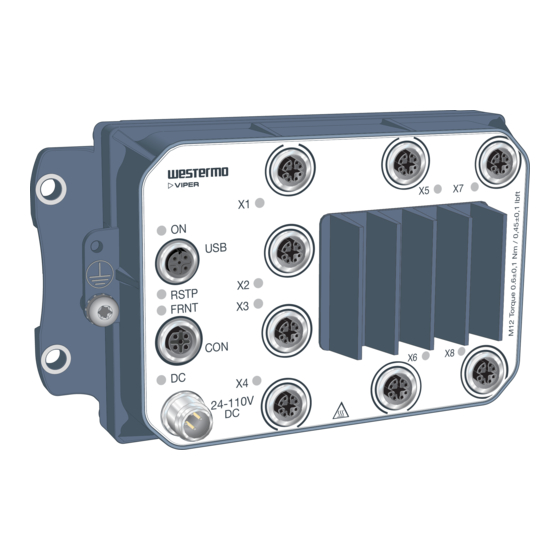
3.3. Hardware Overview RSTP FRNT 24-110 V Figure 3. Location of interface ports and LED indicators Description Description LED indicator Gbps port (8 pcs) GORE-TEX ventilation membrane on Power connection the rear side Console port Protective earth connection USB port Viper-8 Series... -
Page 11: Connector Pinout
+DC1 and +DC2. The negative input for both supplies is -COM Table 3. Power connector Pin no. Signal Illustration No Connect. Do not connect. Table 4. Console connector Pin no. Signal Illustration VBUS No Connect. Do not connect. Table 5. USB connector Viper-8 Series... -
Page 12: Led Indicators
Power OK on DC1 and DC2 Power failure on DC1 or DC2 X1 to X8 No link GREEN Link established GREEN Data traffic indication FLASH YELLOW Port alarm, or port is set in blocking state by link redundancy protocol Table 7. LED indicators Viper-8 Series... -
Page 13: Dimensions
3.6. Dimensions Dimensions are stated in mm and applies to both models. Grounding point Screw M5x10 164 ±0,5 82 ±5 Figure 4. Dimensional drawing Viper-8 Series... -
Page 14: Installation
Use four M5, M6 or 1/4" screws with 12 mm washers on a flat and stable surface. RSTP FRNT 24-110 V Figure 5. Wall mounting 4.2. Protective Earth Connection For correct function, the earth connection needs to be properly connected to a designated PE rail. See the figure below. Torque: 3.2 Nm. Viper-8 Series... -
Page 15: Connection Of Cables
This product has no internal fuse and should be connected via an external fuse for protection. NOTE - UNUSED CONNECTORS Unused connectors must be covered by a protective cap (delivered with the product), tightened to the specified torque in order to fulfill the specified ingress protection code. Viper-8 Series... -
Page 16: Cooling
[15]. For easy replication of the configuration of the original product, it is recommended to have the Westermo USB plug permanently connected to the USB port and move it over to the replacement product before it is powered up. MTTR (Mean Time To Repair), i.e. time for replacement of product is: < 8 minutes. -
Page 17: Specifications
Reverse polarity protected Redundant power input Isolation To all other ports Connector 4-pin, male, M12 screw connection, A-coded, recommended Westermo cables: 3146-1106 for 1.5 m 3146-1107 for 5 m Cable size M12, recommended power cable area 0.5 mm² (minimum 0.25 mm²),... - Page 18 Up to 480 Mbps (high-speed mode) Maximum supply current 500 mA Isolation To all Ethernet and DC ports No isolation to CON or protective earth Connector 5-pin, female, M12 screw connection, A-coded, recommended Westermo USB plug 3641-0190 Circuit type SELV Console port Electrical specification...
-
Page 19: Type Tests And Environmental Conditions
Dielectric strength EN 50155 Power port to all 2250 VDC, 1 min other ports Ethernet ports to 2250 VDC, 1 min all other ports 750 VDC after damp heat, according to EN 50155 Table 8. EMC and electrical conditions Viper-8 Series... - Page 20 Provided all connectors are connected with IP66 and IP67 cablings or fitted with protective caps (delivered with the unit) and tightened to the specified torque. Installation and maintenance shall be made under controlled environments. Table 9. Environmental and mechanical conditions Viper-8 Series...
-
Page 21: Revision Notes
6. Revision Notes Revision Date Change description Rev. C 2021-12 5.1 Interface Specification updated (DC Power port; operating voltage) Rev. B 2021-12 E-mark removed from 2.5.1 Agency Approvals and Standards Compliance Rev. A 2021-10 First version Viper-8 Series... - Page 22 Westermo • Metallverksgatan 6, SE-721 30 Västerås, Sweden Tel +46 16 42 80 00 Fax +46 16 42 80 01 E-mail: info@westermo.com www.westermo.com 6635-2250 REV. C 2021 12 Westermo Network Technologies AB, Sweden...
Need help?
Do you have a question about the Viper-8 Series and is the answer not in the manual?
Questions and answers