Table of Contents
Advertisement
Quick Links
SIMATIC NET
Industrial Ethernet Switches
SCALANCE XF-200G
Operating Instructions
02/2023
C79000-G8976-C676-01
Introduction
Safety notices
Security recommendations
Description of the device
Installing and removing
Connecting up
Maintenance and cleaning
Error correction
Technical specifications
Dimension drawings
Approvals
1
2
3
4
5
6
7
8
9
A
Advertisement
Table of Contents

Subscribe to Our Youtube Channel
Related Manuals for Siemens SIMATIC NET SCALANCE XF-200G


Summary of Contents for Siemens SIMATIC NET SCALANCE XF-200G
- Page 1 Introduction Safety notices Security recommendations SIMATIC NET Description of the device Industrial Ethernet Switches SCALANCE XF-200G Installing and removing Connecting up Operating Instructions Maintenance and cleaning Error correction Technical specifications Dimension drawings Approvals 02/2023 C79000-G8976-C676-01...
- Page 2 Note the following: WARNING Siemens products may only be used for the applications described in the catalog and in the relevant technical documentation. If products and components from other manufacturers are used, these must be recommended or approved by Siemens. Proper transport, storage, installation, assembly, commissioning, operation and maintenance are required to ensure that the products operate safely and without any problems.
-
Page 3: Introduction
You will find the configuration manuals here: • on the data medium that ships with some products: – Product CD / product DVD – SIMATIC NET Manual Collection • On the Internet pages of Siemens Industry Online Support (https:// support.industry.siemens.com/cs/ww/en/ps/15291/man). SCALANCE XF-200G... - Page 4 • On the data medium that ships with some products: – Product CD / product DVD – SIMATIC NET Manual Collection • On the Internet pages of Siemens Industry Online Support under the following entry IDs: – Industrial Ethernet / PROFINET Industrial Ethernet System Manual (https:// support.industry.siemens.com/cs/ww/en/view/27069465)
- Page 5 Siemens’ products and solutions undergo continuous development to make them more secure. Siemens strongly recommends that product updates are applied as soon as they are available and that the latest product versions are used. Use of product versions that are no longer supported, and failure to apply the latest updates may increase customer’s exposure...
- Page 6 Introduction Catalogs You will find the article numbers for the Siemens products of relevance here in the following catalogs: • SIMATIC NET Industrial Communication / Industrial Identification, catalog IK PI • SIMATIC Products for Totally Integrated Automation and Micro Automation, catalog ST 70 •...
-
Page 7: Table Of Contents
Table of contents Introduction ............................3 Safety notices ............................9 Security recommendations........................11 Description of the device ........................19 Product overview ....................... 19 3.1.1 Accessories ........................20 3.1.2 Spare parts ........................21 Device view ........................22 RESET button ........................22 LED display ........................ - Page 8 Table of contents Restoring the factory settings..................... 56 Technical specifications ........................57 Technical specifications of SCALANCE XF204G..............57 Cable lengths........................58 Switching properties ......................58 Mechanical stability (in operation) ..................59 Dimension drawings ..........................61 Dimension drawing XF-200G ..................... 61 Approvals .............................
-
Page 9: Safety Notices
Safety notices Read the safety notices Note the following safety notices. These relate to the entire working life of the device. You should also read the safety notices relating to handling in the individual sections, particularly in the sections "Installation" and "Connecting up". CAUTION To prevent injury and damage, read the manual before using the device. - Page 10 Safety notices SCALANCE XF-200G Operating Instructions, 02/2023, C79000-G8976-C676-01...
-
Page 11: Security Recommendations
OpenVPN). • Separate connections correctly (WBM, SSH etc.). • Check the user documentation of other Siemens products that are used together with the device for additional security recommendations. • Using remote logging, ensure that the system protocols are forwarded to a central logging server. - Page 12 Industrial Security (https://www.siemens.com/ industrialsecurity) website. • Inform yourself regularly about security recommendations published by Siemens ProductCERT (https://www.siemens.com/cert/en/cert-security-advisories.htm). • Only activate protocols that you require to use the device. • Restrict access to the management of the device with rules in an access control list (ACL).
- Page 13 • Verify certificates based on the fingerprint on the server and client side to prevent "man in the middle" attacks. Use a second, secure transmission path for this. • Before sending the device to Siemens for repair, replace the current certificates and keys with temporary disposable certificates and keys, which can be destroyed when the device is returned.
- Page 14 Security recommendations • The following protocols provide secure alternatives: – HTTP → HTTPS – Telnet → SSH – SNMPv1/v2c → SNMPv3 Check whether use of SNMPv1/v2c. is necessary. SNMPv1/v2c is classified as non-secure. Use the option of preventing write access. The device provides you with suitable setting options.
- Page 15 Security recommendations • Configurable port – ✓ The port status can be changed. – -- The port status cannot be changed. • Authentication Specifies whether the communication partner is authenticated. • Encryption Specifies whether or not the transfer is encrypted. List of available services The following is a list of all available services and their ports through which the device can be accessed.
- Page 16 Security recommendations Service Protocol / Port Default port Configurable Authentication Encryption number status Port Service PROFINET UDP/34964 Open ✓ UDP/49151 … 49159 RADIUS Client UPD/1812 Outbound only ✓ ✓ UPD/1813 UDP/3799 Open ✓ ✓ SFTP Server UDP/22 Outbound only ✓ ✓...
- Page 17 Security recommendations Layer 2 service Default Service configura‐ status RSTP Closed ✓ MSTP Open ✓ 1) Setting according to Security by Default. SCALANCE XF-200G Operating Instructions, 02/2023, C79000-G8976-C676-01...
- Page 18 Security recommendations SCALANCE XF-200G Operating Instructions, 02/2023, C79000-G8976-C676-01...
-
Page 19: Description Of The Device
Description of the device Product overview Article numbers Device Description Article number SCALANCE XF204G 4 x 10/100/1000 Mbps ports, PROFINET device 6GK5 204-0GA00-1UF2 Factory settings • Industrial Ethernet protocol: PROFINET • Base bridge mode: 802.1D Transparent Bridge • Redundancy mode: Ring Redundancy •... -
Page 20: Accessories
Description of the device 3.1 Product overview Unpacking and checking WARNING Do not use any parts that show evidence of damage If you use damaged parts, there is no guarantee that the device will function according to the specification. If you use damaged parts, this can lead to the following problems: •... -
Page 21: Spare Parts
Description of the device 3.1 Product overview Mounting plate Component Description Article number Mounting plate Extension Mounting plate for mounting in an Ex‐ 6GK5 980-2HA10-0AA1 unit box tension unit box Including grounding screw Pack of 1 Mounting plate, DIN rail Mounting plate for installation on a DIN 6GK5 980-2HA00-0AA1 rail Including grounding screw... -
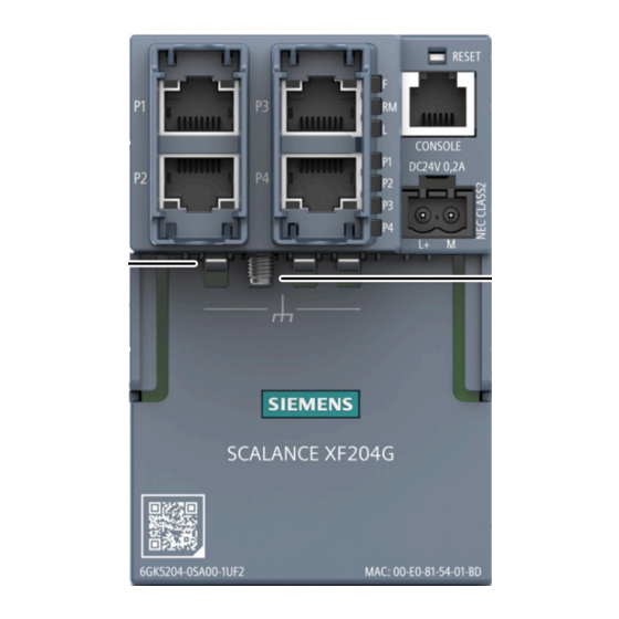
Page 22: Device View
Description of the device 3.3 RESET button Device view The following figure shows an overview of the components of the SCALANCE XF-200G. ① Mounting screw • • Torx T20 • Captive ② LED display • F: Fault LED • RM: redundancy manager •... - Page 23 Description of the device 3.3 RESET button Position The "RESET" button is located on the front of the device. Resetting the device to factory defaults NOTICE Previous settings If you reset, all the settings you have made will be overwritten by factory defaults. NOTICE Inadvertent reset An inadvertent reset can cause disturbances and failures with further consequences in the...
- Page 24 Description of the device 3.3 RESET button Note Damage to the button The RESET button is a short-stroke button with only a slight pressure point. To operate the button, you only need a force 2.5 N (approx. 250 g). To avoid damaging the button press it with little force. Hold the tool you are using, for example, with only two fingers.
-
Page 25: Led Display
Description of the device 3.4 LED display LED display The following figure shows the arrangement of the LEDs: 3.4.1 Fault LED "F" The fault LED "F" indicates the incorrect functioning of the device. LED color LED status Meaning The device is switched off or has not detected a problem. The device has detected a problem. -
Page 26: Rm" Led
Description of the device 3.5 C-PLUG 3.4.2 "RM" LED The "RM" LED indicates whether or not the device is a redundancy manager and whether or not the ring is operating free of error. LED color LED status Meaning The device is not a redundancy manager. Green The device is a redundancy manager. - Page 27 Description of the device 3.5 C-PLUG Saving the configuration data A C-PLUG is an exchangeable storage medium for storing the configuration data of the device. This allows fast and uncomplicated replacement of a device. The C-PLUG is taken from the previous device and inserted in the new device. The first time it is started up, the replacement device has the same configuration as the previous device except for the device-specific MAC address set by the vendor.
-
Page 28: Replacing The C-Plug
Description of the device 3.5 C-PLUG • Command Line Interface (CLI) • PROFINET diagnostics The user then has the choice of either removing the C-PLUG again or selecting the option to reformat the C-PLUG. 3.5.2 Replacing the C-PLUG Position of the C-PLUG NOTICE Do not remove or insert a C-PLUG during operation The C-PLUG may only be removed or inserted when the device is turned off. - Page 29 Description of the device 3.5 C-PLUG Inserting a C-PLUG 1. Turn off the power to the device. 2. The housing of the C-PLUG has a protruding ridge on the long side (B). The slot has a groove at this position. Insert the C-PLUG correctly oriented into the slot. SCALANCE XF-200G Operating Instructions, 02/2023, C79000-G8976-C676-01...
- Page 30 Description of the device 3.5 C-PLUG SCALANCE XF-200G Operating Instructions, 02/2023, C79000-G8976-C676-01...
-
Page 31: Installing And Removing
Installing and removing Safety during mounting Safety notices When installing the device, keep to the safety notices listed below. WARNING If a device is operated in an ambient temperature of more than 50 °C, the temperature of the device housing may be higher than 70 °C. The device must therefore be installed so that it is only accessible to service personnel or users that are aware of the reason for restricted access and the required safety measures at an ambient temperature higher than 50 °C. - Page 32 Installing and removing 4.1 Safety during mounting Safety notices on use in hazardous areas General safety notices relating to protection against explosion WARNING EXPLOSION HAZARD Replacing components may impair suitability for Class 1, Division 2 or Zone 2. WARNING The device is intended for indoor use only. WARNING The device may only be operated in an environment of contamination class 1 or 2 (see EN/IEC 60664-1, GB/T 16935.1).
- Page 33 Installing and removing 4.1 Safety during mounting WARNING EXPLOSION HAZARD For operation the device is intended to be installed within an enclosure/control cabinet. The inner temperature of the enclosure/control cabinet corresponds to the ambient temperature of the device. Use installation wiring connections with admitted maximum operating temperature of at least 30 °C higher than maximum ambient temperature.
-
Page 34: Information On Mounting
Installing and removing 4.2 Information on mounting WARNING Explosion hazard Do not disconnect equipment when a flammable or combustible atmosphere is present. Additional notes CAUTION Use only approved components If you use components and accessories that are not approved for SIMATIC NET devices or their target systems, this may violate the requirements and regulations for safety and electromagnetic compatibility. -
Page 35: Installing In An Extension Unit Box
Installing and removing 4.3 Installing in an Extension unit box Installation position The following mounting position is recommended for DIN-rail mounting: Horizontal Horizontal installation of the rack (DIN rail) Installing in an Extension unit box Required tools To mount the device in an Extension unit box, you need the following: •... - Page 36 Installing and removing 4.3 Installing in an Extension unit box To mount the device inside an Extension Unit box, follow these steps: 1. Remove the rear panel of the Extension Unit box. For more information, see the Product information of the Extension Unit box (Page 3). 2.
- Page 37 Installing and removing 4.3 Installing in an Extension unit box 4. Install the device: – Insert the device so that the guides on the device connect the device to the mounting plate. For an overview of the components of the device, see "Device view (Page 22) –...
- Page 38 Installing and removing 4.3 Installing in an Extension unit box 5. Screw the mounting screw (torque xx Nm). The mounting screw snaps into in a nut on the mounting plate and fixes the device firmly to the mounting plate. In this position, the following components are still accessible: –...
-
Page 39: Mounting On Din Rails
Installing and removing 4.4 Mounting on DIN rails Mounting on DIN rails Required tools To mount the device on a DIN rail, you need the following: • 1 mounting plate for DIN-rail mounting • 1 T20 screwdriver, Torx T20 Installation To install the device on a 35 mm DIN rail complying with DIN EN 60715, follow these steps: 1. - Page 40 Installing and removing 4.4 Mounting on DIN rails ③ 3. Slide the mounting plate upwards and hold it at the uppermost position SCALANCE XF-200G Operating Instructions, 02/2023, C79000-G8976-C676-01...
- Page 41 Installing and removing 4.4 Mounting on DIN rails ④ 4. Screw the mounting screw (torque xx Nm). The mounting screw snaps into in a nut on the mounting plate and fixes the mounting plate firmly to the device. In this position, the mounting plate encloses the lower edge of the DIN rail.
-
Page 42: Uninstalling
Installing and removing 4.5 Uninstalling 3. Pull the device away from the DIN rail. 4. Remove the mounting plate. Uninstalling WARNING Improper disassembly Improper disassembly may result in a risk of explosion in hazardous areas. For proper disassembly, observe the following: •... -
Page 43: Connecting Up
Connecting up Safety when connecting up Safety notices When connecting up the device, keep to the safety notices listed below. WARNING Power supply The device is designed for operation with a directly connectable safety extra low voltage (SELV) from a limited power source (LPS). The power supply therefore needs to meet at least one of the following conditions: •... - Page 44 Connecting up 5.1 Safety when connecting up WARNING Unsuitable cables or connectors Risk of explosion in hazardous areas • Only use connectors that meet the requirements of the relevant type of protection. • If necessary, tighten the connector screw connections, device fastening screws, grounding screws, etc.
- Page 45 Connecting up 5.1 Safety when connecting up Notes for use in hazardous locations according to ATEX, IECEx, UKEX and CCC Ex If you use the device under ATEX, IECEx, UKEX or CCC Ex conditions you must also keep to the following safety instructions in addition to the general safety instructions for protection against explosion: WARNING Transient overvoltages...
-
Page 46: Industrial Ethernet
Connecting up 5.2 Industrial Ethernet Industrial Ethernet The connection to Industrial Ethernet uses the interfaces of the inserted BusAdapter. Therefore, when connecting to Industrial Ethernet, always take note of the information in the BusAdapter operating instructions. You can find additional information on the operating instructions in the "Introduction"... -
Page 47: Wiring Rules
Connecting up 5.3 Wiring rules MDI / MDI-X autocrossover With the MPI/MDI-X autocrossover function, the send and receive contacts of an Ethernet port are assigned automatically. The assignment depends on the cable with which the communications partner is connected. This means that it does not matter whether the port is connected using a patch cable or crossover cable. -
Page 48: Power Supply
Connecting up 5.4 Power supply Wiring rules for ... Spring-loaded terminals Stripped length of the cable 8 - 10 mm Wire end ferrule according to DIN 46228 with plastic ferrule** 8 - 10 mm * AWG: American Wire Gauge ** See note "Wire end ferrules" Note Wire end ferrules Use crimp shapes with smooth surfaces, such as provided by square and trapeze shaped crimp... - Page 49 Connecting up 5.4 Power supply Information on the power supply • The power supply is connected using a 2-pin plug-in terminal block. The terminal block is included in the scope of delivery (Page 19) of the device and can also be ordered as a spare part (Page 21).
-
Page 50: Serial Interface
Connecting up 5.5 Serial interface Serial interface Information on the serial interface • Via the serial interface (RJ-11 jack), you can access the CLI of the device directly via an RS-232 connection (115200 8N1) without assigning an IP address. • Access to the device is also possible independent of the Ethernet ports. •... -
Page 51: Grounding
Connecting up 5.6 Grounding Assignment of the connecting cable The connecting cable listed in the "Accessories" section has the following pin assignment: Contact Pin assignment of the RJ-11 plug Pin assignment of the D-sub female con‐ nector TD (Transmit Data) TD (Transmit Data) RD (Receive Data) SG (Signal Ground) RD (Receive Data) - Page 52 Connecting up 5.6 Grounding 1. Loosen the grounding screw from the mounting plate. 2. Join the ground terminal and grounding screw together. 3. Tighten the grounding screw on the mounting plate (torque 0.75 Nm). SCALANCE XF-200G Operating Instructions, 02/2023, C79000-G8976-C676-01...
-
Page 53: Maintenance And Cleaning
Maintenance and cleaning WARNING Unauthorized repair of devices in explosion-proof design Risk of explosion in hazardous areas • Repair work may only be performed by personnel authorized by Siemens. WARNING Impermissible accessories and spare parts Risk of explosion in hazardous areas •... - Page 54 Maintenance and cleaning SCALANCE XF-200G Operating Instructions, 02/2023, C79000-G8976-C676-01...
-
Page 55: Error Correction
Error correction Downloading new firmware using TFTP without WBM and CLI Firmware The firmware is signed and encrypted. This ensures that only firmware created by Siemens can be downloaded to the device. Pressing the "RESET" button To load new firmware, you require the "RESET" button. When pressing the button, remember the information in the section "RESET button (Page 22)". -
Page 56: Restoring The Factory Settings
Error correction 7.2 Restoring the factory settings Restoring the factory settings NOTICE Previous settings If you reset, all the settings you have made will be overwritten by factory defaults. NOTICE Inadvertent reset An inadvertent reset can cause disturbances and failures with further consequences in the configured network. -
Page 57: Technical Specifications
Technical specifications Technical specifications of SCALANCE XF204G The following technical specifications apply to the SCALANCE XF204G. Technical specifications Connection to Industrial Ethernet Electrical connectors Quantity Connector RJ45 jack Properties Half/full duplex, MDI‑X assignment Transmission speed 10 / 100 / 1000 Mbps Diagnostics interface Serial interface Quantity ... -
Page 58: Cable Lengths
Technical specifications 8.3 Switching properties Technical specifications Mean time between failure (MTBF) MTBF (EN/IEC 61709; 40 °C) > 73 years Note the wiring rules (Page 47). Cable lengths Cable Permitted cable length IE TP torsion cable 0 to 45 m with IE FC Outlet RJ45 + 10 m TP cord + 10 m TP cord IE TP torsion cable 0 to 55 m... -
Page 59: Mechanical Stability (In Operation)
Technical specifications 8.4 Mechanical stability (in operation) Full wire speed switching 148810 1488095 84459 844594 45290 452898 23496 234962 1024 11973 119731 1280 9615 96153 1518 8127 81274 Note The number of SCALANCE XF-200G modules connected in a line influences the frame delay. When a frame passes through the IE switch, this is delayed by the store-and-forward function of the SCALANCE XF-200G by 10-130 microseconds (at 100 Mbps). - Page 60 Technical specifications 8.4 Mechanical stability (in operation) SCALANCE XF-200G Operating Instructions, 02/2023, C79000-G8976-C676-01...
-
Page 61: Dimension Drawings
Dimension drawings Note The dimensions are specified in mm. Dimension drawing XF-200G Front view SCALANCE XF-200G Operating Instructions, 02/2023, C79000-G8976-C676-01... - Page 62 Dimension drawings 9.1 Dimension drawing XF-200G Side view Underside SCALANCE XF-200G Operating Instructions, 02/2023, C79000-G8976-C676-01...
-
Page 63: Approvals
Current approvals on the Internet You will find the current approvals for the product on the Internet pages of Siemens Industry Online Support (https://support.industry.siemens.com/cs/ww/en/ps/15273/cert). Notes for the manufacturers of machines This product is not a machine in the sense of the EC Machinery Directive or the Supply of Machinery (Safety) Regulations (UK). - Page 64 Process Automation DE-76181 Karlsruhe Germany Importer UK: Siemens plc, Manchester M20 2UR You can find the current UK Declaration of Conformity for these products on the Internet pages under Siemens Industry Online Support (https:// support.industry.siemens.com/cs/ww/en/ps/15273/cert). SCALANCE XF-200G Operating Instructions, 02/2023, C79000-G8976-C676-01...
- Page 65 "SIMATIC NET Product Information Use of subassemblies/modules in a Zone 2 Hazardous Area". You will find this document • on the data medium that ships with some devices. • on the Internet pages under Siemens Industry Online Support (https:// support.industry.siemens.com/cs/ww/en/view/78381013).
- Page 66 Approvals EMC (electromagnetic compatibility) The SIMATIC NET products described in these operating instructions meet the electromagnetic compatibility requirements according to the EU Directive 2014/30/EU as well as the UK- Regulation SI 2016/1091 and their associated amendments. Applied standards: • EN 61000‑6‑2 Electromagnetic compatibility (EMC) - Part 6-2: Generic standards - Immunity for industrial environments •...
- Page 67 Approvals Underwriters Laboratories Inc. complying with • UL 62368-1 (information/communication technology) • CSA C22.2 No. 62368-1 (information/communication technology) • ANSI/ISA 12.12.01 • CSA C22.2 No. 213 Approved for use in Cl. 1, Div. 2, GP A, B, C, D T4 Cl.
- Page 68 • "Industrial Ethernet / PROFINET Industrial Ethernet" System Manual (https:// support.industry.siemens.com/cs/ww/en/view/27069465) • "Industrial Ethernet / PROFINET - Passive Network Components" System Manual (https:// support.industry.siemens.com/cs/ww/en/view/84922825) • "EMC Installation Guidelines" configuration manual (https:// support.industry.siemens.com/cs/ww/en/view/60612658)
-
Page 69: Index
Index Accessories, 20 Glossary, 5 Ambient conditions, 57 Approvals, 63 Article numbers, 19 Autonegotiation, 47 Housing, 57 AWG, 47 Installation, 57 Button, 55, 56 DIN-rail mounting, 39 Extension unit box, 36 Cable cross section, 47 CE mark, 63 LED display CLI, 50 Fault LED, 25 Command Line Interface, 50 Port LED, 26 Command Line Interface (CLI), 28, 55 RM LED, 25 Configuration, 24 Connection to Industrial Ethernet, 57 C-PLUG, 20... - Page 70 Index Safety notices for installation, 31 general, 9 Use in hazardous areas, 9, 31, 43 when connecting up, 43 Scope of delivery, 19 Serial interface, 50 SIMATIC NET glossary, 5 SIMATIC NET manual, 4 Spare parts, 21 Startup phase, 24, 56 System manual, 4, 34, 68 Web Based Management (WBM), 28, 55 Weight, 57 Wiring, 47 Wiring rules, 49...
Need help?
Do you have a question about the SIMATIC NET SCALANCE XF-200G and is the answer not in the manual?
Questions and answers