Siemens SIMATIC NET SCALANCE XF-200BA Operating Instructions Manual
Industrial ethernet switches
Hide thumbs
Also See for SIMATIC NET SCALANCE XF-200BA:
- Configuration manual (618 pages) ,
- Operating instructions manual (64 pages)
Table of Contents
Advertisement
Quick Links
SIMATIC NET
Industrial Ethernet switches
SCALANCE XF-200BA
Operating Instructions
02/2023
C79000-G8976-C470-08
Introduction
Safety notices
Recommendations on
network security
Description of the device
Installation and removal
Connecting up
Maintenance and cleaning
Error correction
Technical specifications
Dimension drawings
Approvals
1
2
3
4
5
6
7
8
9
A
Advertisement
Table of Contents

Related Manuals for Siemens SIMATIC NET SCALANCE XF-200BA


Summary of Contents for Siemens SIMATIC NET SCALANCE XF-200BA
- Page 1 Introduction Safety notices Recommendations on network security SIMATIC NET Description of the device Industrial Ethernet switches SCALANCE XF-200BA Installation and removal Connecting up Operating Instructions Maintenance and cleaning Error correction Technical specifications Dimension drawings Approvals 02/2023 C79000-G8976-C470-08...
- Page 2 Note the following: WARNING Siemens products may only be used for the applications described in the catalog and in the relevant technical documentation. If products and components from other manufacturers are used, these must be recommended or approved by Siemens. Proper transport, storage, installation, assembly, commissioning, operation and maintenance are required to ensure that the products operate safely and without any problems.
-
Page 3: Introduction
• On the data medium that is supplied with some products: – Product CD/product DVD – SIMATIC NET Manual Collection • On the Internet pages of Siemens Industry Online Support: – SCALANCE BusAdapter (https://support.industry.siemens.com/cs/ww/en/ps/25085/man) – SIMATIC BusAdapter (https://support.industry.siemens.com/cs/ww/en/ps/14072/man) SCALANCE XF-200BA... - Page 4 • On the data medium that ships with some products: – Product CD / product DVD – SIMATIC NET Manual Collection • On the Internet pages of Siemens Industry Online Support under the following entry IDs: – Industrial Ethernet / PROFINET Industrial Ethernet System Manual (https:// support.industry.siemens.com/cs/ww/en/view/27069465)
- Page 5 Siemens’ products and solutions undergo continuous development to make them more secure. Siemens strongly recommends that product updates are applied as soon as they are available and that the latest product versions are used. Use of product versions that are no longer supported, and failure to apply the latest updates may increase customer’s exposure...
- Page 6 Catalogs You will find the article numbers for the Siemens products of relevance here in the following catalogs: • SIMATIC NET Industrial Communication / Industrial Identification, catalog IK PI •...
-
Page 7: Table Of Contents
Table of contents Introduction ............................3 Safety notices ............................9 Recommendations on network security ....................11 Description of the device ........................19 Properties and functions ....................19 Product overview ....................... 21 3.2.1 Accessories ........................23 3.2.2 Spare parts ........................26 Device views ........................ - Page 8 Table of contents Maintenance and cleaning ........................55 Error correction............................ 57 Downloading new firmware using TFTP without WBM and CLI..........57 Restoring the factory settings..................... 58 Technical specifications ........................59 SCALANCE XF-200BA technical specifications ..............59 Cable lengths........................61 8.2.1 Copper cable (RJ45 connector)...................
-
Page 9: Safety Notices
Safety notices Read the safety notices Note the following safety notices. These relate to the entire working life of the device. You should also read the safety notices relating to handling in the individual sections, particularly in the sections "Installation" and "Connecting up". CAUTION To prevent injury and damage, read the manual before using the device. - Page 10 Safety notices SCALANCE XF-200BA Operating Instructions, 02/2023, C79000-G8976-C470-08...
-
Page 11: Recommendations On Network Security
OpenVPN). • Separate connections correctly (WBM, SSH etc.). • Check the user documentation of other Siemens products that are used together with the device for additional security recommendations. • Using remote logging, ensure that the system protocols are forwarded to a central logging server. - Page 12 Industrial Security (https://www.siemens.com/ industrialsecurity) website. • Inform yourself regularly about security recommendations published by Siemens ProductCERT (https://www.siemens.com/cert/en/cert-security-advisories.htm). • Only activate protocols that you require to use the device. • Restrict access to the management of the device with rules in an access control list (ACL).
- Page 13 • Verify certificates based on the fingerprint on the server and client side to prevent "man in the middle" attacks. Use a second, secure transmission path for this. • Before sending the device to Siemens for repair, replace the current certificates and keys with temporary disposable certificates and keys, which can be destroyed when the device is returned.
- Page 14 Recommendations on network security • The following protocols provide secure alternatives: – HTTP → HTTPS – Telnet → SSH – SNMPv1/v2c → SNMPv3 Check whether use of SNMPv1/v2c. is necessary. SNMPv1/v2c is classified as non-secure. Use the option of preventing write access. The device provides you with suitable setting options.
- Page 15 Recommendations on network security • Configurable port – ✓ The port status can be changed. – -- The port status cannot be changed. • Authentication Specifies whether the communication partner is authenticated. • Encryption Specifies whether or not the transfer is encrypted. List of available services The following is a list of all available services and their ports through which the device can be accessed.
- Page 16 Recommendations on network security Service Protocol / Port Default port Configurable Authentication Encryption number status Port Service PROFINET UDP/34964 Open ✓ UDP/49151 … 49159 RADIUS Client UPD/1812 Outbound only ✓ ✓ UPD/1813 UDP/3799 Open ✓ ✓ SFTP Server UDP/22 Outbound only ✓...
- Page 17 Recommendations on network security Layer 2 service Default Service configura‐ status RSTP Closed ✓ MSTP Open ✓ 1) Setting according to Security by Default. SCALANCE XF-200BA Operating Instructions, 02/2023, C79000-G8976-C470-08...
- Page 18 Recommendations on network security SCALANCE XF-200BA Operating Instructions, 02/2023, C79000-G8976-C470-08...
-
Page 19: Description Of The Device
Description of the device Properties and functions Y functionality With the IE switch SCALANCE XF204-2BA DNA you can connect a redundant PROFINET ring consisting of S2 devices (field area) to a fault-tolerant PROFINET system (R1 system). DNA stands for Dual Network Access or also Y switch functionality. Devices with Y functionality do not support VLANs. - Page 20 Description of the device 3.1 Properties and functions SIMATIC S7-410-5H SCALANCE XF204-2BA PROFINET / Industrial Ethernet (redundant automation system) SCALANCE XF204-2BA PROFINET/ Industrial Ethernet SIMATIC ET 200SP HA SCALANCE XF204-2BA DNA (Y-Switch) HART (4...20 mA) SIMATIC ET 200M SINAMICS S120 SCALANCE XC-200 SIMOTICS M SIMATIC...
-
Page 21: Product Overview
Description of the device 3.2 Product overview Product overview Article numbers Basic devices The following table shows the available basic devices that are delivered without BusAdapters: Device Description Article number SCALANCE XF204-2BA Up to 4 x 10/100 Mbps ports via 2 bus adapter slots, PROFINET 6GK5 204-2AA00-2GF2 device, extended temperature range, coated printed circuit boards (conformal coating) - Page 22 Description of the device 3.2 Product overview Type designation The type designation of a SCALANCE XF-200BA is made up of several parts that have the following meaning: Standard version Dual Network Access Number of bus adapters Number of usable ports Unpacking and checking WARNING Do not use any parts that show evidence of damage If you use damaged parts, there is no guarantee that the device will function according to the...
-
Page 23: Accessories
02 from firmware version V4.0. • The C-PLUG with 256 MB is supported by the SCALANCE XF204-2BA DNA with hardware revision 01 from firmware version V4.4. See also SCALANCE XF-200BA (https://support.industry.siemens.com/cs/de/en/ps/24708/pm) SCALANCE XF-200BA DNA (https://support.industry.siemens.com/cs/de/en/ps/24742/pm) BusAdapter Component Description Article number BA 2×RJ45 *... - Page 24 Description of the device 3.2 Product overview Component Description Article number BA 2×FC * PROFINET bus adapter with 2 FastConnect Ethernet 6ES7 193-6AF00-0AA0 connectors for direct connection of the bus cable BA 2×FC (Coated) * PROFINET bus adapter with 2 FastConnect Ethernet 6AG1 193-6AF00-7AA0 connectors for direct connection of the bus cable, extended temperature range, with coated printed- circuit boards (conformal coating)
- Page 25 Description of the device 3.2 Product overview Component Description Article number BA LC/RJ45 PROFINET BusAdapter with 1 glass fiber-optic con‐ 6DL1 193-6AG20-0AA0 nector, LC connection system and 1 Ethernet socket SIMATIC ET 200SP HA for standard RJ45 plugs (Conformal Coating) From production ver‐ sion FS01 BA LC/FC PROFINET BusAdapter with 1 glass fiber-optic con‐...
-
Page 26: Spare Parts
Description of the device 3.2 Product overview Strain relief Component Description Article number Strain relief Screw-on strain relief for guiding the outgo‐ 6ES7 193-6RA00-1AN0 ing cables The strain relief is a mechanical protective device for the electrical and optical cables on the bus adapter. -
Page 27: Device Views
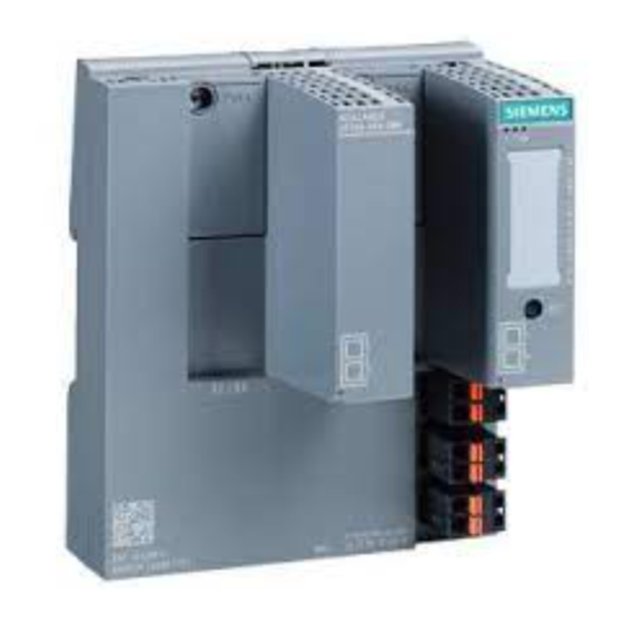
Description of the device 3.4 SET button Device views The following figure shows an overview of the components of the SCALANCE XF-200BA. ① BaseUnit with slots for 2 bus adapters without covers The BaseUnit provides the electrical and mechanical connection of the bus adapters. ②... - Page 28 Description of the device 3.4 SET button Position The "SET" button is located on the front of the SCALANCE XF-200BA. Figure 3-2 Position of the "SET" button on the SCALANCE XF-200BA Resetting the device to factory defaults NOTICE Previous settings If you reset, all the settings you have made will be overwritten by factory defaults. NOTICE Inadvertent reset An inadvertent reset can cause disturbances and failures in a configured network with further...
-
Page 29: Led Display
Description of the device 3.5 LED display Procedure To reset the device to the factory defaults during operation, follow the steps below: 1. Press the "SET" button. 2. Hold down the button for approximately 12 seconds. After 9 seconds, the fault LED "F" flashes for 3 seconds. –... -
Page 30: Rm" Led
Description of the device 3.6 C-PLUG 3.5.3 "RM" LED The "RM" LED indicates whether or not the device is a redundancy manager and whether or not the ring is operating free of error. LED color LED status Meaning The device is not a redundancy manager. Green The device is a redundancy manager. - Page 31 Description of the device 3.6 C-PLUG How it works Operating mode In terms of the C-PLUG, there are three modes for the device: • Without C-PLUG The device stores the configuration in internal memory. This mode is active if no C-PLUG is inserted. •...
-
Page 32: Replacing The C-Plug
Description of the device 3.6 C-PLUG 3.6.2 Replacing the C-PLUG Position of the C-PLUG NOTICE Do not remove or insert a C-PLUG during operation The C-PLUG may only be removed or inserted when the device is turned off. The C-PLUG slot is on the front of the device. Replacing a C-PLUG. - Page 33 Description of the device 3.6 C-PLUG Inserting a C-PLUG 1. Turn off the power to the device. 2. The housing of the C-PLUG has a protruding ridge on the long side (B). The slot has a groove at this position. Insert the C-PLUG correctly oriented into the slot. SCALANCE XF-200BA Operating Instructions, 02/2023, C79000-G8976-C470-08...
- Page 34 Description of the device 3.6 C-PLUG SCALANCE XF-200BA Operating Instructions, 02/2023, C79000-G8976-C470-08...
-
Page 35: Installation And Removal
Installation and removal Safety notices for installation Safety notices When installing the device, keep to the safety notices listed below. WARNING If a device is operated in an ambient temperature of more than 50 °C, the temperature of the device housing may be higher than 70 °C. The device must therefore be installed so that it is only accessible to service personnel or users that are aware of the reason for restricted access and the required safety measures at an ambient temperature higher than 50 °C. - Page 36 Installation and removal 4.1 Safety notices for installation Safety notices on use in hazardous areas General safety notices relating to protection against explosion WARNING EXPLOSION HAZARD Replacing components may impair suitability for Class 1, Division 2 or Zone 2. WARNING The device is intended for indoor use only. WARNING The device may only be operated in an environment of contamination class 1 or 2 (see EN/IEC 60664-1, GB/T 16935.1).
- Page 37 Installation and removal 4.1 Safety notices for installation WARNING EXPLOSION HAZARD For operation the device is intended to be installed within an enclosure/control cabinet. The inner temperature of the enclosure/control cabinet corresponds to the ambient temperature of the device. Use installation wiring connections with admitted maximum operating temperature of at least 30 °C higher than maximum ambient temperature.
- Page 38 Installation and removal 4.1 Safety notices for installation WARNING Explosion hazard Do not disconnect equipment when a flammable or combustible atmosphere is present. Additional notes CAUTION Use only approved components If you use components and accessories that are not approved for SIMATIC NET devices or their target systems, this may violate the requirements and regulations for safety and electromagnetic compatibility.
-
Page 39: Mounting On Din Rails
Installation and removal 4.2 Mounting on DIN rails Mounting on DIN rails Installation Figure 4-1 DIN rail mounting To install the device on a 35 mm DIN rail complying with DIN EN 60715, follow the steps below: ① 1. Place the housing guide of the device on the top edge of the DIN rail ②... -
Page 40: Mounting Bus Adapters
Installation and removal 4.3 Mounting bus adapters To remove the device from a DIN rail, follow the steps below: 1. Disconnect all connected cables. ① 2. Release the DIN rail locking mechanism by pressing down on the release button ② 3. Pull the lower part of the device away from the DIN rail Mounting bus adapters NOTICE Do not install or uninstall a bus adapter during operation... - Page 41 Installation and removal 4.3 Mounting bus adapters Installation Figure 4-3 Mounting bus adapters To fit a bus adapter, follow the steps below: 1. Turn off the power to the device. 2. Remove the cover of the bus adapter slot. 3. If necessary mount a strain relief, see section "Mounting tensile strain relief (Page 42)". ①...
-
Page 42: Mounting Tensile Strain Relief
Installation and removal 4.4 Mounting tensile strain relief Mounting tensile strain relief Required tools • Torx screwdriver, size T10 • Cable ties We recommend cable ties with a width of 4.8 mm. The maximum width is 7.0 mm. The length of the cable tie is min. 60 mm. Installation Figure 4-4 Mounting tensile strain relief... -
Page 43: Disassembly
Installation and removal 4.5 Disassembly Disassembly WARNING Improper disassembly Improper disassembly may result in a risk of explosion in hazardous areas. For proper disassembly, observe the following: • Before starting work, ensure that the electricity is switched off. • Secure remaining connections so that no damage can occur as a result of disassembly if the system is accidentally started up. - Page 44 Installation and removal 4.5 Disassembly SCALANCE XF-200BA Operating Instructions, 02/2023, C79000-G8976-C470-08...
-
Page 45: Connecting Up
Connecting up Safety when connecting up Safety notices When connecting up the device, keep to the safety notices listed below. WARNING Power supply The device is designed for operation with a directly connectable safety extra low voltage (SELV) from a limited power source (LPS). The power supply therefore needs to meet at least one of the following conditions: •... - Page 46 Connecting up 5.1 Safety when connecting up WARNING Unsuitable cables or connectors Risk of explosion in hazardous areas • Only use connectors that meet the requirements of the relevant type of protection. • If necessary, tighten the connector screw connections, device fastening screws, grounding screws, etc.
- Page 47 Connecting up 5.1 Safety when connecting up Notes for use in hazardous locations according to ATEX, IECEx, UKEX and CCC Ex If you use the device under ATEX, IECEx, UKEX or CCC Ex conditions you must also keep to the following safety instructions in addition to the general safety instructions for protection against explosion: WARNING Transient overvoltages...
-
Page 48: Industrial Ethernet
Connecting up 5.2 Industrial Ethernet Industrial Ethernet The connection to Industrial Ethernet uses the interfaces of the inserted BusAdapter. Therefore, when connecting to Industrial Ethernet, always take note of the information in the BusAdapter operating instructions. You can find additional information on the operating instructions in the "Introduction"... - Page 49 Connecting up 5.2 Industrial Ethernet MDI / MDI-X autocrossover With the MPI/MDI-X autocrossover function, the send and receive contacts of an Ethernet port are assigned automatically. The assignment depends on the cable with which the communications partner is connected. This means that it does not matter whether the port is connected using a patch cable or crossover cable.
-
Page 50: Optical
Connecting up 5.2 Industrial Ethernet 5.2.2 Optical NOTICE Failure of the data traffic due to contamination of optical plug-in connections Optical sockets and plugs are sensitive to contamination of the end face. Contamination can lead to the failure of the optical transmission network. Take the following precautions to avoid functional impairments: •... -
Page 51: Wiring Rules
Connecting up 5.4 Power supply Wiring rules When wiring use cables with the following AWG categories or cross sections. Wiring rules for ... Spring-loaded terminals connectable cable cross sec‐ without wire end ferrule 0.25 - 2.5 mm tions for flexible cables ... AWG: 24 - 14 with wire end ferrule** 0.25 - 2.5 mm... - Page 52 Connecting up 5.4 Power supply CAUTION Damage to the device due to overvoltage The connector of the external power supply is not protected against strong electromagnetic pulses that can, for example, result from lightning strikes or switching large loads. One of the tests used to attest the immunity of devices of the IE switches SCALANCE XF-200BA to electromagnetic interference, among others, is the "surge immunity test"...
-
Page 53: Signaling Contact
Connecting up 5.5 Signaling contact Contact Assignment 24 VDC Ground Signaling contact Information on the signaling contact • The signaling contact is a floating switch that signals error statuses by opening the contact. The signaling contact must be operated within the range of the operating voltage. If an error/fault occurs, the signaling contact opens. -
Page 54: Grounding
Connecting up 5.6 Grounding Signaling faults • The signaling of errors by the signaling contact is synchronized with the fault LED "F", see section ""F" LED (Page 29)". All errors that the fault LED "F" indicates (freely configurable) are also signaled by the signaling contact. -
Page 55: Maintenance And Cleaning
Maintenance and cleaning WARNING Unauthorized repair of devices in explosion-proof design Risk of explosion in hazardous areas • Repair work may only be performed by personnel authorized by Siemens. WARNING Impermissible accessories and spare parts Risk of explosion in hazardous areas •... - Page 56 Maintenance and cleaning SCALANCE XF-200BA Operating Instructions, 02/2023, C79000-G8976-C470-08...
-
Page 57: Error Correction
Error correction Downloading new firmware using TFTP without WBM and CLI Firmware The firmware is signed and encrypted. This ensures that only firmware created by Siemens can be downloaded to the device. Procedure with Microsoft Windows Using TFTP, you can supply a device with new firmware even when it cannot be reached using WBM or CLI. -
Page 58: Restoring The Factory Settings
Error correction 7.2 Restoring the factory settings Restoring the factory settings NOTICE Previous settings If you reset, all the settings you have made will be overwritten by factory defaults. NOTICE Inadvertent reset An inadvertent reset can cause disturbances and failures with further consequences in the configured network. -
Page 59: Technical Specifications
Technical specifications SCALANCE XF-200BA technical specifications Technical specifications Connection to Industrial Ethernet Slots for bus adapters Quantity Ports per bus adapter Connector Depending on the bus adapter Properties Half/full duplex, MDI‑X pinning Transmission speed 10 / 100 Mbps Optical data (basic device with corresponding bus adapters) POF cable Transmitter output (optical) •... - Page 60 Technical specifications 8.1 SCALANCE XF-200BA technical specifications Technical specifications Effective power loss 24 VDC 2.4 W Fusing 2.5 A (non-replaceable fuse F) Signaling contact Quantity Design Terminal block, 2 terminals Permitted voltage range 24 VDC Load capability max. 100 mA Permitted ambient conditions Ambient temperature During opera‐...
-
Page 61: Cable Lengths
Technical specifications 8.2 Cable lengths Ambient temperature during operation The maximum ambient temperature during operation depends on the bus adapters plugged in. The temperature values that apply to the bus adapters are specified on the bus adapters. If the temperature values of the plugged in bus adapters are lower than those of the basic device, the values of the bus adapters apply. -
Page 62: Plastic Optical Fiber (Scrj Connector)
Technical specifications 8.2 Cable lengths 8.2.2 Plastic Optical Fiber (SCRJ connector) Properties Transmission method 100Base-FX complying with IEEE 802.3 Transmission speed 100 Mbps (Fast Ethernet) Transmission medium Multimode fiber-optic cable Light source Wavelength 650 nm Cable length (max.) ... -
Page 63: Switching Properties
Technical specifications 8.3 Switching properties Properties Wavelength 1300 nm Cable length (max.) * At 50 µm fiber core diameter 3 km At 62.5 µm fiber core diameter 3 km Transmitter output (optical) Minimum At 50 μm -24 dBm At 62.5 μm -20 dBm Maximum... -
Page 64: Mechanical Stability (In Operation)
Technical specifications 8.4 Mechanical stability (in operation) Note The number of SCALANCE XF-200BA modules connected in a line influences the frame delay. When a frame passes through the IE switch, this is delayed by the store-and-forward function of the SCALANCE XF-200BA by 10-130 microseconds (at 100 Mbps). Mechanical stability (in operation) Mechanical stability (in operation) Device... -
Page 65: Dimension Drawings
Dimension drawings Note The dimensions are specified in mm. SCALANCE XF-200BA Operating Instructions, 02/2023, C79000-G8976-C470-08... - Page 66 Dimension drawings SCALANCE XF-200BA Operating Instructions, 02/2023, C79000-G8976-C470-08...
-
Page 67: Approvals
Current approvals on the Internet You will find the current approvals for the product on the Internet pages of Siemens Industry Online Support (https://support.industry.siemens.com/cs/ww/en/ps/15273/cert). Notes for the manufacturers of machines This product is not a machine in the sense of the EC Machinery Directive or the Supply of Machinery (Safety) Regulations (UK). - Page 68 Process Automation DE-76181 Karlsruhe Germany Importer UK: Siemens plc, Manchester M20 2UR You can find the current UK Declaration of Conformity for these products on the Internet pages under Siemens Industry Online Support (https:// support.industry.siemens.com/cs/ww/en/ps/15273/cert). SCALANCE XF-200BA Operating Instructions, 02/2023, C79000-G8976-C470-08...
- Page 69 "SIMATIC NET Product Information Use of subassemblies/modules in a Zone 2 Hazardous Area". You will find this document • on the data medium that ships with some devices. • on the Internet pages under Siemens Industry Online Support (https:// support.industry.siemens.com/cs/ww/en/view/78381013).
- Page 70 Approvals Note for devices with CLASS 1 LASER Important note on products certified according to Type Examination Certificate KEMA 07ATEX0145 X as of Issue 95 / DEKRA 18ATEX0025 X and IECEx Certificate of Conformity DEK 14.0025X as of Issue 43 / DEK 18.0017X and containing Class 1 optical radiation sources. Note CLASS 1 LASER The device contains optical radiation sources which comply with the limits of Class 1 according...
- Page 71 Approvals cULus approval for industrial control equipment cULus Listed IND. CONT. EQ. Underwriters Laboratories Inc. complying with • UL 61010-2-201 • CAN/CSA-IEC 61010-2-201 Report no. E85972 cULus Approval Hazardous Location cULus Listed IND. CONT. EQ. FOR HAZ. LOC. Underwriters Laboratories Inc. complying with •...
- Page 72 • "Industrial Ethernet / PROFINET Industrial Ethernet" System Manual (https:// support.industry.siemens.com/cs/ww/en/view/27069465) • "Industrial Ethernet / PROFINET - Passive Network Components" System Manual (https:// support.industry.siemens.com/cs/ww/en/view/84922825) • "EMC Installation Guidelines" configuration manual (https:// support.industry.siemens.com/cs/ww/en/view/60612658)
-
Page 73: Index
Index Accessories, 23 Housing, 60 Approvals, 67 Article numbers, 21 Autonegotiation, 49 AWG, 51 Installation, 60 Installation on a DIN rail, 39 Strain relief, 42 Installation on a DIN rail, 39 BusAdapter, 3 Button, 57, 58 MDI / MDI-X autocrossover, 49 MTBF, 60 Cable cross section, 51 CE mark, 67 Command Line Interface (CLI), 31, 57 Components of the product, 22 Permitted ambient conditions, 60 Configuration, 28 Pin assignment, 48... - Page 74 Index Web Based Management (WBM), 31, 57 Weight, 60 Wiring, 51 Wiring rules, 53 SCALANCE XF-200BA Operating Instructions, 02/2023, C79000-G8976-C470-08...
Need help?
Do you have a question about the SIMATIC NET SCALANCE XF-200BA and is the answer not in the manual?
Questions and answers