Table of Contents
Advertisement
Quick Links
Tel : +44 (0)1798 877000
Fax : +44 (0)1798 872479
e-mail :
hvsales@spellmanhv.co.uk
Broomers Park, Broomers Hill Lane
Pulborough, W. Sussex, RH20 2RY
High Voltage Power Supply
MPS 20W 1kV to 20kV SERIES
SAFETY AND INSTALLATION
INSTRUCTIONS
Document number: 80552-4
1
2
Issue
16/06/09
18/06/09
Date
I-1518
5732U
Issuing Authority
Checked
Approved
Spellman High Voltage Electronics Limited
Company Confidential
This document must not be copied or distributed without express permission from Spellman High Voltage
Electronics Limited
Issue 2
Page 1 of 16
Advertisement
Table of Contents

Related Manuals for Spellman MPS Series


Summary of Contents for Spellman MPS Series
- Page 1 Issue 16/06/09 18/06/09 Date I-1518 5732U Issuing Authority Checked Approved Spellman High Voltage Electronics Limited Company Confidential This document must not be copied or distributed without express permission from Spellman High Voltage Electronics Limited Issue 2 Page 1 of 16...
-
Page 2: Change History
HANGE ISTORY Section Reason for Change Issue Original 5 – table 1 Output impedances changed to 2k2. Issue 2 Page 2 of 16... - Page 3 SAFETY DANGER HIGH VOLTAGE RISK OF ELECTROCUTION Observe extreme caution when working with this equipment High voltage power supplies must always be connected to a protective earth Do not touch connections unless equipment is turned off and the capacitance of both the load and power supply are grounded Allow adequate time for discharge of internal capacitance of the power supply...
-
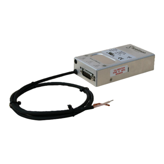
Page 4: Unit Description
Unit Description The MPS series of high voltage dc-dc converters is a range of units designed to produce a high quality dc output for a very wide range of instrumentation and analytical applications. The combination of linear and switch mode power conversion techniques provide low noise and high efficiency. -
Page 5: Explanation Of Symbols
2. Safety The HV output of the unit is hazardous and the conditions of this manual must be complied with to maintain safety. The unit is contained in an earthed case with a screened HV output cable and the HV output cable must be terminated safely before the unit is operated. -
Page 6: Applicable Standards
4. Applicable standards The unit is CE marked and the standard units are UL listed. The Standards applied are: BS EN61010-1: 2001 and UL61010A-1 Safety requirements for electrical equipment for measurement, control and laboratory use. Issue 2 Page 6 of 16... -
Page 7: Installation
5. Installation The connector details on the standard unit and VCC versions are shown in table 1 overleaf. The DCC version is shown in table 2. See section 5 for more information on various connection methodologies. Table 1 : Non /DCC units connector pin-out Signal Name Parameters Power Ground... - Page 8 Table 2 : /DCC units connector pin-out Signal Name Parameters Power/Signal Ground Ground +24Vdc Input +24Vdc @ 2A maximum Voltage Monitor Output Not used Local Programming Potentiometer connected to +10Vdc reference and Potentiometer Wiper Output ground, 0 to 10Vdc adjustable wiper output provided Internal Connection Do not connect Voltage Program Differential...
- Page 9 Mechanical Outline 1kV to 10kV units. Customer Adjust Point 150.0 15w D-plug TOP OF UNIT CALIBRATION VOID IF SEAL Fixing face BROKEN SIDE OF UNIT HOLE Ø3.5mm IN 3 POSITIONS MOUNTING HOLE TEMPLATE VIEWED FROM TOP OF UNIT (NOTE - Max thread depth into unit is 5mm) Unit Footprint 12.0 46.0...
- Page 10 Mechanical Outline 15kV to 20kV units. Customer Adjust Point 185.0 15w D-plug TOP OF UNIT CALIBRATION VOID IF SEAL Fixing face BROKEN SIDE OF UNIT HOLE Ø4.5mm IN 3 POSITIONS MOUNTING HOLE TEMPLATE VIEWED FROM TOP OF UNIT (NOTE - Max thread depth into unit is 7mm) Unit Footprint 12.0 46.0...
-
Page 11: Connection Details
6. Connection Details 6.1. Remote DAC control The differential input allows the voltage programming circuit to be remote from the power supply. It prevents voltage drops in the ground connection from affecting the programming signal. However, if there are voltage drops in the ground connection, the DAC should be provided with its own reference. - Page 12 6.2 Local DAC control The unit has an internal potentiometer near the D type input connector, which is conected to the +10V reference. The output from the wiper of the internal pot may be used as a reference for the DAC. Set the internal pot to maximum to make the +10V reference available to external circuits.
- Page 13 Internal potentiometer control The unit has an internal potentiometer near the D type input connector, which is connected to the +10V reference. The unit may be controlled by the internal potentiometer as follows: - 24V Power input on Pin 2. Ground on Pin 1.
- Page 14 6.4 External potentiometer control The unit has an internal potentiometer near the D type input connector, which is connected to the +10V reference. An external potentiometer may be connected to the wiper of the internal pot. Set the internal pot to give the desired maximum output voltage and control the unit using the external potentiometer.
- Page 15 RS232 control (/DCC) versions only The unit has RS232 (or RS485) communication facilities available via pins 14 and 15 of the 15 way ‘D’ connector. For the protocol used refer to unit specification, the ‘standard’ protocol can be provided on request. The unit may be controlled digitally as follows: - 24V Power input on Pin 2.
- Page 16 Note: Failure to comply with the above could compromise the safe operation of the unit and invalidate the warranty. Issue 2 Page 16 of 16...
Need help?
Do you have a question about the MPS Series and is the answer not in the manual?
Questions and answers