Table of Contents
Advertisement
Quick Links
Tel: +44 (0)1798 873986
Fax: +44 (0)1798 872479
E-mail:
hvsales@spellmanhv.co.uk
Broomers Park, Broomers Hill Lane
Pulborough, W. Sussex, RH20 2RY
Installation and User Guide
MXR20PN24 and MXR30PN24
Document Number: 81317-4.
Issue
B
C
1
Date
10/04/18
15/09/20
05/03/2021
Issuing Authority
I-5820
I-7349
10377P
Checked
Approved
Advertisement
Table of Contents

Related Manuals for Spellman MXR20PN24


Summary of Contents for Spellman MXR20PN24
- Page 1 Tel: +44 (0)1798 873986 Fax: +44 (0)1798 872479 E-mail: hvsales@spellmanhv.co.uk Broomers Park, Broomers Hill Lane Pulborough, W. Sussex, RH20 2RY Installation and User Guide MXR20PN24 and MXR30PN24 Document Number: 81317-4. Issue Date 10/04/18 15/09/20 05/03/2021 Issuing Authority I-5820 I-7349 10377P...
- Page 2 Do not ground yourself or work under wet or damp conditions Servicing Safety No maintenance is required Servicing should only be done by qualified personnel aware of the hazards If in doubt, return to supplier for servicing 81317-4r1 MXR20PN24 & MXR30PN24 Installation & User Guide 2 of 10...
-
Page 3: Table Of Contents
High Voltage Connection ....................9 Operation of the HV Unit ....................10 Analogue Interface ....................... 10 4.1.1 Analogue Control Inputs ....................10 4.1.2 Analogue Output Monitors ....................10 HV On Indicators ........................10 81317-4r1 MXR20PN24 & MXR30PN24 Installation & User Guide 3 of 10... -
Page 4: Unit Description
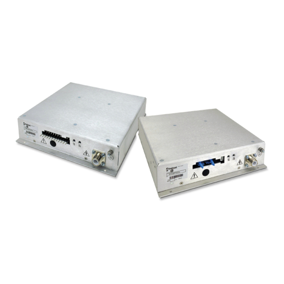
Unit Description The HV power units MXR20PN24 and MXR30PN24 are intended for use in mass spectrometry, electron microscopy, capillary electrophoresis and electrostatic printing applications, they consist of one aluminium chassis containing the high voltage power supply. Control and monitoring of the units is accomplished via either analogue controls on the standard... - Page 5 81317-4r1 MXR20PN24 & MXR30PN24 Installation & User Guide 5 of 10...
-
Page 6: Mating Cable Details
No. 61010-1. Please consult the factory for further approval information. 2.2 Meaning of Symbols SYMBOL MEANING Refer to manual before operating Caution, possibility of electric shock Protective conductor terminal (PE) 81317-4r1 MXR20PN24 & MXR30PN24 Installation & User Guide 6 of 10... -
Page 7: Installation Of The Hv Unit
3.1 Initial Inspection Inspect the package exterior for evidence of damage due to handling in transit. Notify the carrier and Spellman immediately if damage is evident. Do not destroy or remove any of the packing material used in a damaged shipment. -
Page 8: Connections
1. 24V power input connections are via a 2 way Molex Mini-fit Jr connector, Part Number 39- 30-1021. Power connector pin assignments table Signal Name +24V DC Ground return for +24V 81317-4r1 MXR20PN24 & MXR30PN24 Installation & User Guide 8 of 10... -
Page 9: High Voltage Connection
Note: Take care in choosing suitable ground connection for pin 2. 3.4.3 High Voltage Connection High Voltage output is via a GES HB30 high voltage receptacle for all versions. 81317-4r1 MXR20PN24 & MXR30PN24 Installation & User Guide 9 of 10... -
Page 10: Operation Of The Hv Unit
4.2 HV On Indicators The MXR units use the following LEDs indicate polarity when the power supply is enabled and optional interlock is enabled: • HV +ve” “ • “HV -ve” 81317-4r1 MXR20PN24 & MXR30PN24 Installation & User Guide 10 of 10...
Need help?
Do you have a question about the MXR20PN24 and is the answer not in the manual?
Questions and answers