Table of Contents
Advertisement
Quick Links
Advertisement
Table of Contents

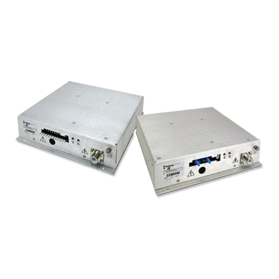
Summary of Contents for Spellman MXR Series
- Page 1 Tel : +44 (0)1798 877000 hvsales@spellmanhv.co.uk Broomers Park, Pulborough, W. Sussex, UK. RH20 2RY Product: MXR Series Title: Installation and User Guide Document Number: 81317-4 Issue: Date: 08/November/2021 © 2021 Spellman High Voltage Electronics Corporation...
-
Page 2: Table Of Contents
Power input connector ......................10 4.3.2 Control connector ........................10 HV On Indicators ........................... 11 Appendix A - Mechanical layout ........................12 MXR Series – Installation and User Guide Document Number: 81317-4 Issue: 2 Spellman High Voltage Electronics Limited | +44 (0)1798 877000 | hvsales@spellmanhv.co.uk... - Page 3 Servicing should only be done by qualified personnel aware of the hazards Return to supplier for servicing MXR Series – Installation and User Guide Document Number: 81317-4 Issue: 2 Spellman High Voltage Electronics Limited | +44 (0)1798 877000 | hvsales@spellmanhv.co.uk...
- Page 4 L'entretien ne doit être effectué que par un personnel qualifié et conscient des dangers. Il n'y a pas de piéce remplaçables par l'utilisateur dans l'unité, retourner au fournisseur pour l'entretien. MXR Series – Installation and User Guide Document Number: 81317-4 Issue: 2 Spellman High Voltage Electronics Limited | +44 (0)1798 877000 | hvsales@spellmanhv.co.uk...
-
Page 5: Unit Description
Storage Temperature: -35°C to +85°C Humidity: 0% to 80% RH (non-condensing) Altitude: 0 to 2000m ASL MXR Series – Installation and User Guide Document Number: 81317-4 Issue: 2 Spellman High Voltage Electronics Limited | +44 (0)1798 877000 | hvsales@spellmanhv.co.uk | Broomers Park, Pulborough, W. Sussex, UK. RH20 2RY ©... -
Page 6: Safety
Regulatory Approvals The unit is designed to meet the requirements of EN 61010-1, UL 61010-1 and CAN/CSA-22.2 No. 61010-1. Please consult datasheet or the factory for further approval information. MXR Series – Installation and User Guide Document Number: 81317-4 Issue: 2... -
Page 7: Installing The Unit
Initial Inspection Inspect the package exterior for evidence of damage due to handling in transit. Notify the carrier and Spellman immediately if damage is evident. Do not destroy or remove any of the packing material used in a damaged shipment. -
Page 8: Connections And Unit Operation
3330007 Note: Customised versions of the MXR units can be developed with an HV output cable encapsulated into the unit, UL style 3873. Please consult with factory. MXR Series – Installation and User Guide Document Number: 81317-4 Issue: 2 Spellman High Voltage Electronics Limited | +44 (0)1798 877000 | hvsales@spellmanhv.co.uk... -
Page 9: Analog Version - Connections And Operation
Mating connector is not provided. Mating receptacle: for example, Molex KK 508 3001 part number 10-01-1124, with Molex crimps: KK 396 part number: 08-55-0106, and wire gauge of 18 to 26 AWG. MXR Series – Installation and User Guide Document Number: 81317-4 Issue: 2... -
Page 10: Digital Version - Connections And Operation
• Revision 3D and onwards (4D or 4E etc.) for the MXR20 units • Revision 2B and onwards for the MXR30 units MXR Series – Installation and User Guide Document Number: 81317-4 Issue: 2 Spellman High Voltage Electronics Limited | +44 (0)1798 877000 | hvsales@spellmanhv.co.uk... -
Page 11: Hv On Indicators
The MXR units use the following LEDs to indicate polarity when the unit is powered, and the optional interlock is enabled: • HV +VE • HV -VE MXR Series – Installation and User Guide Document Number: 81317-4 Issue: 2 Spellman High Voltage Electronics Limited | +44 (0)1798 877000 | hvsales@spellmanhv.co.uk | Broomers Park, Pulborough, W. -
Page 12: Appendix A - Mechanical Layout
Page 12 of 12 Appendix A - Mechanical layout MXR Series – Installation and User Guide Document Number: 81317-4 Issue: 2 Spellman High Voltage Electronics Limited | +44 (0)1798 877000 | hvsales@spellmanhv.co.uk | Broomers Park, Pulborough, W. Sussex, UK. RH20 2RY ©...


Need help?
Do you have a question about the MXR Series and is the answer not in the manual?
Questions and answers