Sign In
Upload
Manuals
Brands
Neutronics Manuals
Measuring Instruments
NTRON Mini-ICS
Neutronics NTRON Mini-ICS Gas Analyzer Manuals
Manuals and User Guides for Neutronics NTRON Mini-ICS Gas Analyzer. We have
1
Neutronics NTRON Mini-ICS Gas Analyzer manual available for free PDF download: Operation Manual
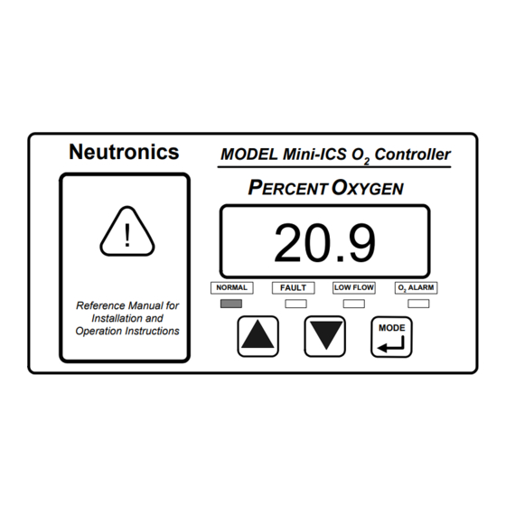
Neutronics NTRON Mini-ICS Operation Manual (78 pages)
OXYGEN ANALYZER / CONTROLLER – PERCENT RANGE
Brand:
Neutronics
| Category:
Measuring Instruments
| Size: 0 MB
Table of Contents
Table of Contents
3
For Your Safety
7
Welcome
8
Chapter 1 - Introduction and Overview
9
General
9
Features
10
System Hardware Overview
11
Main Board
11
Relay Board
11
Power Supply
11
Display Board
11
Control Panel
12
Chassis
12
System Inputs and Outputs
14
Oxygen Sensor Input
14
Flow Switch Status Input
14
Alarm Relay Output
14
Inert Gas Control Relay Output
14
Fault Relay Output
15
Remote Calibration Relay Output
15
Analog Voltage Output
15
Analog Current Output
15
Range ID Output
16
Service Port
16
Front Panel User Interface
17
The "UP" Pushbutton
17
The "DOWN" Pushbutton
17
The "MODE" Pushbutton
17
7-Segment Alphanumeric Display
17
Normal Indicator LED
17
Alarm Indicator LED
17
Low Flow Indicator LED
17
Fault Indicator LED
18
Chapter 2 - System Installation and Start-Up
19
Installing the Analyzer
19
Step 1 - Locate and Mount the Analyzer Unit
20
Step 2 - Install the Oxygen Sensor
21
Step 3 - Install the Analyzer
21
Oxygen Sensor Input
24
Flow Switch Status Input
24
Oxygen Alarm Relay Outputs
24
Inert Gas Control Relay Outputs
25
Fault Relay Outputs
25
Remote Calibration Relay Outputs
25
Analog Voltage Output
26
Analog Current Output
26
Range ID Output
26
RS-232 Service Port
27
Battery Backup
27
Mains Power
28
Starting up and Commissioning the System
29
STEP 1 - Power up the Unit
29
STEP 2 - Calibrate the Unit
31
STEP 3 -Set Alarms, and Inert Gas Control Limits
31
Set Oxygen Alarm Level
31
Set High Inert Gas Control Limit
31
Set Low Inert Gas Control Limit
31
Chapter 3 - Analyzer Operation
33
System Organization
33
User Modes
33
CALIBRATE Mode
33
When to Calibrate
33
What Gases to Use
33
Procedure for Calibrating the Model Mini-ICS
34
Set Oalarm
35
ALARM Mode
35
SET HIGH INERT GAS CONTROL LIMIT Mode
35
SET LOW INERT GAS CONTROL LIMIT Mode
35
VIEW ACTIVE FAULTS Mode
35
Run Modes
37
NORMAL Mode
37
ALARM ACTIVE Mode
37
INERTING CONTROL ACTIVE Mode
38
FAULT ACTIVE Mode
39
Chapter 4 - Maintenance and Troubleshooting
41
System Setup
41
System Setup Via Front Panel Keypad
41
User Setup 1: ICS and O2 Alarm Relays Failsafe/Non Failsafe.4-2
42
User Setup 2: O2 Alarm Relays Ascending Trip
42
User Setup 3: Analog Voltage Output Setting
42
User Setup 4: Analog Current Output Setting
42
User Setup 5: Display Range Setup
42
User Setup 6: RS-232 Baud Rate
42
User Setup 7: Serial Output Format
42
User Setup 8: Sensor Disconnect Detection Test
43
User Setup 9: Minimum Analog Output Voltage Concentration
43
User Setup 10: Maximum Analog Output Voltage Concentration4-3
43
User Setup 11: Minimum Analog Output Current Concentration4-3
43
User Setup 12: Analog Current Full Scale
43
Not Active for this
44
Release
44
User Setup 14: Set Current Month
44
User Setup 15: Set Current Day
44
Not Active for this Release
44
User Setup 16: Set Current Hour
44
User Setup 17: Set Current Minute
44
User Setup 18: Factory Setup Restore
44
System Setup Via Service Port
44
RS-232 Service Port Interfacing with Hyperterminal in Microsoft Windows 95 or Later
44
Troubleshooting Your Hyperterminal Interface
45
Organization of RS-232 Serial Data
45
Standard Level Access
46
Advanced Level 1 Access
46
Advanced Level-2 Access
46
SETTING up the MODEL Mini-ICS - the RS-232 User Setup Menu4-10
50
System Information Display
50
U20) Alarm and Relay Setup Menu
50
U30) Analog Output Setup Menu
52
U04) Display/Analog Output Range
55
U50) RS-232 Serial Setup Menu
55
U60) Front Panel Locks Menu
56
U70) Auto Calibration Setup Menu
57
Sensor Disconnect Test
58
Set Time-Of-Day and Date ** NOT ACTIVE for this RELEASE**4-19
59
Averaging Window Size
59
Auto Return to Run Mode Time
59
Return All Settings to Factory Delivered Settings
59
Change Factory Settings Via Hardware Jumpers
60
Analog Voltage Output
60
Routine Periodic Maintenance
62
Troubleshooting
63
Fault Codes
63
Fault Code 0 - Constant Memory Error
63
Fault Code 1 - Low Flow
63
Fault Code 2 - Sensor Disconnected
63
Fault Code 4 - Low Sensor Limit Higher than Low ICS Limit
63
Fault Code 5 - High ICS Limit Lower than Low ICS Limit
64
Fault Code 6 - Unstable Calibration Sample
64
Fault Code 7 - Sensor Calibration Signal High
64
Fault Code 8- Sensor Calibration Signal Low
64
Fault Code 9 - Sensor Analog-To-Digital Converter Time-Out4-24
64
Fault Code 10 - Sensor Operating Signal Low
65
Fault Code 11 - Calibration Period too Short
65
Fault Code 17 - Bad Cell Calibration Coefficient
65
Fault Code 18 - Main-Board EEPROM Corrupted
65
Fault Code 27 - Auto Calibration Mode Active
65
Fault Code 28 - Calibration Mode Active
65
Fault Code 29 - Manual Relay Control Active
65
Fault Code 30 - User Setup Mode Active
66
Fault Code 31 - Factory Setup Mode Active
66
Fault Code 32 - Program Starting
66
Appendixa - Spare Parts List
67
Appendixb - Specifications
68
Appendix C - Analyzer Factory Configuration Settings
71
APPENDIX D - Front Panel Hot-Key Functions
73
Appendix E - Warranty
74
Intended Use for the Model Mini-Ics
74
Appendix F - Reference Drawings
75
Appendix G - Mounting Configurations
76
Wall Mount Enclosure
76
Rack Mount Enclosure
77
Explosion Proof Enclosure
78
Advertisement
Advertisement
Related Products
Neutronics 7-08-1000-51-0
Neutronics 7100E
Neutronics MINI ID
Neutronics QUICK DETECT
Neutronics ULTIMA ID
Neutronics ULTIMA ID PRO RI-700H
Neutronics UltimaID
Neutronics YELLOW JACKET 68945
Neutronics YELLOW JACKET 68947
Neutronics YELLOW JACKET 68948
Neutronics Categories
Measuring Instruments
Analytical Instruments
Controller
Industrial Equipment
More Neutronics Manuals
Login
Sign In
OR
Sign in with Facebook
Sign in with Google
Upload manual
Upload from disk
Upload from URL