
Subscribe to Our Youtube Channel
Related Manuals for Renesas HIP2105-6MBEVAL1Z


Summary of Contents for Renesas HIP2105-6MBEVAL1Z
- Page 1 HIP2105-6MBEVAL1Z User’s Manual: Evaluation Board Industrial Analog and Power Rev.1.00 Jul 2018...
-
Page 2: Specifications
UG167 Evaluation Board Rev.1.00 Jul 31, 2018 Overview The HIP2105-6MBEVAL1Z is an evaluation tool for the HIP2105 HIP2106A half bridge MOSFET drivers. This tool consists of a mother board and HIP2105DBEVAL1Z or HIP2106ADBEVAL1Z evaluation daughter cards. The mother board platform provides an on-board microcontroller that is used to generate appropriate control inputs to the HIP2105 or HIP2106A. - Page 3 External Inputs Microcontroller Buffer Option External Switches LI, HI/PWM Bias Multiplexer Jumper Option HIP2105 HIP2106A Daughter Card Half Bridge FETs Optional DC Motor or other Loads Figure 1. HIP2105-6MBEVAL1Z Block Diagram UG167 Rev.1.00 Page 3 of 30 Jul 31, 2018...
-
Page 4: Functional Description
The HIP2105-6MBEVAL1Z is a fully self-contained test platform for evaluation of the HIP2105 or the HIP2106A, which are provided on daughter cards. The HIP2105-6MBEVAL1Z mother board and associated daughter cards are the same test boards used by the Renesas application engineers and IC designers to evaluate the performance of the HIP2105 and HIP2106A MOSFET drivers. -
Page 5: Half Bridge
HIP2105-6MBEVAL1Z 2. Functional Description Half Bridge The bridge is composed of two (NVTFS5C466NLWF) 51A, 40V MOSFETs. Each FET has an optional gate-to- source and drain-to-gate capacitors to allow the emulation of FETs with larger capacitances if desired. An optional series gate resistor is also provided for each bridge FET that can also be used the emulate the internal gate resistance. - Page 6 HIP2105-6MBEVAL1Z 2. Functional Description User Assembly Options The following optional assembly features are provided on the evaluation mother board: • Series connected diode (D1) on the VBAT input to the HIP2106A daughter card for holding up V when there is severe ripple voltage from a Li-ion battery.
- Page 7 HIP2105-6MBEVAL1Z 2. Functional Description The following user optional assembly features are provided on the HIP2105, HIP2106A daughter cards. • The HO = HGATE and LO = LGATE outputs have options for a bypass diode across a series connected gate resistor for slower turn-on and faster turn-off of the driven bridge FET. The default configuration includes the bypass diode in parallel with a 0Ω...
- Page 8 HIP2105-6MBEVAL1Z 2. Functional Description • The PHASE pin has an RC filter (R on the HIP2105 daughter card and R on the HIP2106A daughter card) This filter is used if needed. The default value for R is 0Ω and the capacitor between Phase and VSS is omitted.
- Page 9 HIP2105-6MBEVAL1Z 2. Functional Description with the internal inductance of the Li-ion battery (typically a few hundred nH). If the capacitor value is large enough, the battery voltage is close to the nominal unloaded value with minimal ripple. Another approach to reduce the amplitude of the voltage transient from the battery without increasing the size or value of the bridge capacitor, is to increase the PWM switching frequency.
- Page 10 HIP2105-6MBEVAL1Z 2. Functional Description Table 1. DIP Switch Options Switch Position PWM Frequency 25kHz 50kHz 100kHz 200kHz 300kHz 400kHz 500kHz 625kHz External inputs Dead Time 0.0µs 0.1µs 0.2µs 0.3µs 0.4µs 0.5µs 0.6µs 0.7µs (4) Connect scope probes on the HI/PWM and LI test points on the mother board. Set the time base to 50ns/Div, the vertical gain to 2V/Div, the trigger on the LI input at the 2.5V level with a negative edge...
- Page 11 HIP2105-6MBEVAL1Z 2. Functional Description (9) Slowly rotate the potentiometer, R , to the right (CW) until the waveforms shown in Figure 7 appear. HI/PWM Figure 7. HI/PWM and LI Signals (10) Confirm that a the preset dead time is present.
- Page 12 HIP2105-6MBEVAL1Z 2. Functional Description (10) Turn the potentiometer CW until the waveform shown in Figure 8 appears. HI/PWM PHASE Figure 8. HI/PWM, LI, and Phase Signals (11) Confirm that the PWM frequency is 200kHz on the HI/PWM and LI pins.
-
Page 13: Pcb Layout Guidelines
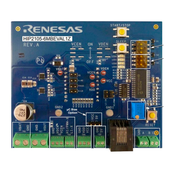
3. PCB Layout Guidelines PCB Layout Guidelines The HIP2105-6MBEVAL1Z board is 84mmx94mm. The tallest component is the RJ25 connector. The total height is 38mm. Multiple inputs have miniature terminal blocks and the high current battery inputs and load outputs have larger terminal blocks rated for 15A each connection. - Page 14 HIP2105-6MBEVAL1Z 3. PCB Layout Guidelines Observe the Installation Polarity Figure 10. HIP2105-6MBEVAL1Z Bottom View UG167 Rev.1.00 Page 14 of 30 Jul 31, 2018...
- Page 15 LI-C UNNAMED_4_HC125_I174_Y SK2-3 SK1-3 VOUT TB4-2 SK2-2 SK1-2 OPEN LI-X SK2-1 SK1-1 TB7-2 UNNAMED_4_NCHANNEL_I179_G1X HI/PWM-IN HI/PWM-X NVTFS5C466NL VCEN-X VDEN_X TB5-3 TB6-3 DRAWN BY: DATE: ENGINEER: DATE: TIM KLEMANN 04/25/2018 THEJU BERNARD Figure 11. HIP2105-6MBEVAL1Z Bridge and Daughter Card Socket Schematic...
- Page 16 1 0 0 x x x 0.4µs DRAWN BY: DATE: 1 0 1 x x x 0.5µs TIM KLEMANN 4/25/201 RELEASED BY: DATE: 1 1 0 x x x 0.6µs UPDATED BY: DATE: 1 1 1 x x x 0.7µs TESTER Figure 12. HIP2105-6MBEVAL1Z Controller...
- Page 17 UGATE PHASE J1-9 J2-9 J1-8 BOOT J2-8 J1-7 J2-7 UGATE PHASE J2-6 BOOT 0.1UF UGATE-OUT J1-6 J2-5 24.9 HI-IN PHASE-OUT J2-4 J1-5 LGATE LI-IN LGATE-OUT J2-3 J1-4 LGATE 24.9 HIP2105FRZ AGND J1-3 AGND J2-2 J1-2 J2-1 J1-1 Figure 13. HIP2105DBEVAL1Z Daughter Card Schematic...
- Page 18 UGATE PHASE LGATE J1-9 J2-9 J1-8 BOOT J2-8 J1-7 J2-7 UGATE PHASE UNNAMED_1_HIP2106A_I224_9 J2-6 BOOT VCTRL 0.1UF UGATE-OUT J1-6 J2-5 24.9 HI-IN PHASE-OUT J2-4 J1-5 LGATE-OUT J2-3 J1-4 LGATE 24.9 AGND HIP2106AIRZ AGND J1-3 J2-2 J1-2 J2-1 J1-1 Figure 14. HIP2106ADBEVAL1Z Daughter Card Schematic...
-
Page 19: Board Layouts
HIP2105-6MBEVAL1Z 3. PCB Layout Guidelines Board Layouts 3.3.1 HIP2105DBEVAL1Z Figure 15. HIP2105DBEVAL1Z Top Silkscreen UG167 Rev.1.00 Page 19 of 30 Jul 31, 2018... - Page 20 HIP2105-6MBEVAL1Z 3. PCB Layout Guidelines Figure 16. HIP2105DBEVAL1Z Top Layer Figure 17. HIP2105DBEVAL1Z Bottom Layer UG167 Rev.1.00 Page 20 of 30 Jul 31, 2018...
- Page 21 HIP2105-6MBEVAL1Z 3. PCB Layout Guidelines 3.3.2 HIP2106ADBEVAL1Z Figure 18. HIP2106ADBEVAL1Z Top Silkscreen Figure 19. HIP2106ADBEVAL1Z Top Layer UG167 Rev.1.00 Page 21 of 30 Jul 31, 2018...
- Page 22 HIP2105-6MBEVAL1Z 3. PCB Layout Guidelines Figure 20. HIP2106ADBEVAL1Z Bottom Layer 3.3.3 HIP2105-6MBEVAL1Z Figure 21. HIP2105-6MBEVAL1Z Top Silkscreen UG167 Rev.1.00 Page 22 of 30 Jul 31, 2018...
- Page 23 HIP2105-6MBEVAL1Z 3. PCB Layout Guidelines Figure 22. HIP2105-6MBEVAL1Z Top Layer Figure 23. HIP2105-6MBEVAL1Z Bottom Layer UG167 Rev.1.00 Page 23 of 30 Jul 31, 2018...
- Page 24 HIP2105-6MBEVAL1Z 3. PCB Layout Guidelines Figure 24. HIP2105-6MBEVAL1Z Bottom Silkscreen UG167 Rev.1.00 Page 24 of 30 Jul 31, 2018...
- Page 25 BAT54W-V-GS08 D3, D4 DIODE-RECTIFIER, SMD, 2P, SMA, 50V, 1A, ROHS DIODES INC. ES1A-13-F IC-SYNCHRONOUS MOSFET DRIVER, 10P, DFN, 3X3, ROHS RENESAS ELECTRONICS AMERICA HIP2105FRZ R5, R6 RES, SMD, 0603, 24.9Ω, 1/10W, 1%, TF, ROHS PANASONIC ERJ-3EKF24R9V RES, SMD, 0603, DNP-PLACE HOLDER, ROHS R1, R2, R7 RES, SMD, 0805, 0Ω, 1/8W, TF, ROHS...
- Page 26 Table 4. HIP2105-6MBEVAL1Z Bill of Materials Reference Designator Description Manufacturer Manufacturer Part PWB-PCB, HIP2105-6MBEVAL1Z, REVA, ROHS IMAGINEERING INC HIP2105- 6MBEVAL1ZREVAPCB C13, C14 CAP, SMD, 1210, 10µF, 50V, 10%, X7S, ROHS C3225X7S1H106K C2, C7 CAP, SMD, 0603, .01µF, 50V, 10%, X7R, ROHS...
- Page 27 Table 4. HIP2105-6MBEVAL1Z Bill of Materials (Continued) Reference Designator Description Manufacturer Manufacturer Part R2, R3, R5, R8, R11, R13, RES, SMD, 0603, 10k, 1/10W, 1%, TF, ROHS VENKEL CR0603-10W-1002FT R15, R17, R25, R27, R28, R19, R21 RES, SMD, 0603, 100k, 1/10W, 1%, TF, ROHS...
-
Page 28: Revision History
HIP2105-6MBEVAL1Z 4. Revision History Revision History Rev. Date Description 1.00 Jul 31, 2018 Updated part number from: HIP2105IRZ to: HIP2105FRZ, in Figure 13 and in Table 2 - HIP2105DBEVAL1Z Bill of Materials. 0.00 Jun 5, 2018 Initial release UG167 Rev.1.00... - Page 29 10. It is the responsibility of the buyer or distributor of Renesas Electronics products, or any other party who distributes, disposes of, or otherwise sells or transfers the product to a third party, to notify such third party in advance of the contents and conditions set forth in this document.
- Page 30 HIP2105-6MBEVAL1Z UG167...
- Page 31 Mouser Electronics Authorized Distributor Click to View Pricing, Inventory, Delivery & Lifecycle Information: Renesas Electronics HIP2105-6MBEVAL1Z HIP2105DBEVAL1Z...
Need help?
Do you have a question about the HIP2105-6MBEVAL1Z and is the answer not in the manual?
Questions and answers