
Related Manuals for Megger PDS 60


Summary of Contents for Megger PDS 60
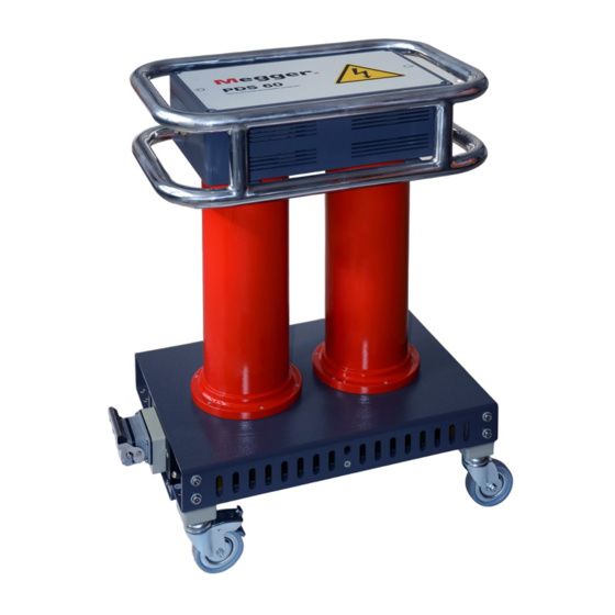
- Page 1 PDS 60 / PDS 60-HP Partial discharge measuring system USER GUIDE Issue: D (09/2022) - EN Article number: 84004...
-
Page 3: Consultation With Megger
The information in this document is subject to change without notice and should not be construed as a commitment by Megger. Megger cannot be made liable for technical or printing errors or shortcomings of this handbook. Megger also disclaims all responsibility for damage resulting... -
Page 4: Terms Of Warranty
Each component and product replaced in accordance with this warranty becomes the property of Megger. All warranty claims versus Megger are hereby limited to a period of 12 months from the date of delivery. Each component supplied by Megger within the context of warranty will also be covered by this warranty for the remaining period of time but for 90 days at least. -
Page 5: Table Of Contents
Contents Contents Consultation with Megger ....................3 Terms of Warranty ......................4 Contents ........................... 5 Safety Instructions ................... 7 General Notes ....................7 General Safety Instructions and Warnings ............9 Technical Description ..................10 Abbreviations ....................10 System Description ..................11 Technical Data .................... - Page 6 Contents Manual Evaluation of Partial Discharges ............56 6.1.1 Determining Possible Sources of PD Faults ............ 56 6.1.2 Analysing Individual PD Events ............... 57 Preparing and Printing the Report ..............60 Configuring Settings and Managing Data............ 63 Adjusting the Settings – ................
-
Page 7: Safety Instructions
It is important to observe the generally applicable electrical regulations of the country in Working with products which the device will be installed and operated, as well as the current national accident from Megger prevention regulations and internal company directives (work, operating and safety regulations). - Page 8 Safety Instructions The system may only be installed and operated by an authorised electrician. DIN VDE Operating staff 0104 (EN 50191), DIN VDE 0105 (EN 50110) and the German accident prevention regulations (UVV) define an electrician as someone whose knowledge, experience and familiarity with the applicable regulations enables him to recognise potential hazards.
-
Page 9: General Safety Instructions And Warnings
If, contrary to the regulations, any other extinguishing agent is • used for fire fighting, this may lead to damage at the electrical installation. Megger disclaims any liability for consequential damage. Furthermore, when using a powder extinguisher near high-voltage installations, there is a danger that the operator of the fire extinguisher will get an electrical shock from a voltage arc-over (due to the powder dust created). -
Page 10: Technical Description
Technical Description Technical Description Abbreviations In this manual the following abbreviations are used: Partial Discharge Damped AC Very Low Frequency PDIV Partial Discharge Inception Voltage PDEV Partial Discharge Extinction Voltage Time Domain Reflectometry (or Time Domain Reflectometer) Cosine Rectangular Test and Diagnosis System Monitored Withstand Test Voltage Withstand Diagnosis Ankoppelvierpol (Quadripole) -
Page 11: System Description
Technical Description System Description The PDS 60 / PDS 60-HP is a partial discharge measurement system that allows for the Functional description identification, classification and location of PD faults in the insulation and the accessories of all kinds of medium voltage cables. - Page 12 Technical Description System configuration The partial discharge measurement system PDS 60 / PDS 60-HP acts as link between the voltage source and the test object and is responsible for the decoupling and capturing of the measurement signals. It consists of the HV filter, components for the signal decoupling (coupling capacitor, measuring impedance, measurement amplifier) and the PD detector that is responsible for the signal processing.
- Page 13 QTY Component Description Article number Partial discharge Standard version: measurement system 1014865 PDS 60 / PDS 60-HP High Power version (HP): 1014866 Software license 3 dongles included 90011937 PD calibrator Conformity:...
- Page 14 If you have a test voltage with sine wave output voltage that is not listed here (for example, from a different manufacturer), please contact the sales representative responsible for you to determine whether it can be used together with the PDS 60 / PDS 60-HP.
-
Page 15: Technical Data
Technical Description Technical Data The partial discharge measurement system PDS 60 / PDS 60-HP and the included PD detector are specified by the following parameters Parameter Value Voltage range max. 60 kV Maximum load capacitance 2.4 µF (standard version) 4.4 µF (HP version) -
Page 16: Technical Background
Technical Background To be informed about the condition and residual life of their resources is increasingly What is Partial important for network operators in order to be able to plan and optimise the investment Discharge and why test and maintenance measures. for it? By the use of condition-based maintenance of medium voltage cable networks with the help of cable diagnosis and cable tests, it is possible to considerably reduce the costs for... - Page 17 How can PD be In order to measure partial discharges, the test object is applied with the required voltage. The generated high-frequency PD signals are decoupled by means of a special AKV. measured and located? By gradually raising the voltage it is possible to detect at which voltage the PD ignites (PDIV) and how the PD level changes with increasing voltage.
-
Page 18: Connection Elements And Status Leds
Connection Elements and Status LEDs The coupling unit has the following and connection elements and status LEDs: Element Description HV input (from test voltage source) HV output (to the test object) Status LEDs indicating the following states: Left LED Right LED Green Measurement underway Software and PD detector... -
Page 19: Commissioning
Commissioning Commissioning General safety instructions for set-up and commissioning The safety guidelines for the operation of mobile testing systems • often differ from one network operator to another and are frequently subject to national regulations (such as the German BGI 5191). WARNING Before the measurement session, find out what the applicable guidelines are and follow the rules set out therein precisely, in... -
Page 20: Electrical Connection In Combination With A Stand-Alone Test Voltage Source
Commissioning 3.1.1 Electrical Connection in Combination with a Stand-Alone Test Voltage Source The following picture shows the electrical connection with a test voltage source suitable Connection diagram for direct connection (e.g. TDS40): Test voltage source Station earth or other suitable foundation earth electrode Prohibition zone and test area acc. - Page 21 This way, unnecessary high basic interference levels can be avoided. Connect the HV output of the PDS 60 / PDS 60-HP with the phase conductor of the cable that is to be tested by means of the supplied HV connection cable.
- Page 22 Commissioning Step Action Connect the test voltage source to a power socket. An optional external safety device can be connected in between the power outlet and the power inlet in order to ensure norm-compliant signalling and Emergency Stop according to DIN EN 50191 / VDE 0104. For detailed information regarding the input voltage range and the external safety device, please read the manual of the test voltage source.
- Page 23 Commissioning Using the optional connection box (see page 13) it is also possible to use Megger test Connection using voltage sources that have a network connection but that are not prepared for the optional connection connection of the control line (for example, VLF Sinus 34 kV). The connection to the...
-
Page 24: Electrical Connection Of A Test Van
3.1.2 Electrical Connection of a Test Van The PDS 60 / PDS 60-HP can be easily used as diagnosis attachment in a test van as Prerequisites long as the van is equipped with a suitable test attachment (see page 14) and the required connection equipment. -
Page 25: Switching On
Commissioning Switching On For stand-alone systems, in addition to the test system itself, it may also be necessary Switching on the test to turn on the connection box used for the connection. voltage source In a test van the test voltage source is turned on automatically once the settings needed for the start of a PD measurement have been configured on the control unit. -
Page 26: Basic Operation Of The Software
Basic Operation of the Software Basic Operation of the Software Start Screen After the PD measurement software has been opened, the main menu appears which enables the user to call up the individual modules of the software: Main menu of the PC software Main menu of the test van software The following modules are available: Module Description... -
Page 27: Useful Features Of The Software
Basic Operation of the Software Useful Features of the Software In order to make the search in extensive lists (e.g. cable lists) easier there is always a Search and sort search form near the list in which any character string can be entered. While entering, the functions list is immediately filtered by entries that contain this character string. - Page 28 Basic Operation of the Software To guarantee quick access to frequently used cable templates, these can be added to the Administration of favourites favourites ( ) list by clicking on the symbol, or be removed from the list ( ) by clicking again.
-
Page 29: Conducting Measurements
Conducting Measurements Conducting Measurements Starting or Resuming a Measurement Task – Before starting the actual measurement, a measurement task must be created or opened in the first step, under which all recorded measurement data are stored until either the software is closed or a new measurement job is started. You can either…... - Page 30 Conducting Measurements Step Action If required, select the version of the PD Detector in use from the PD Detector drop down list. The drop down list is only available if more than one PD detector is configured in the software Information on the version of the PD Detector can be found on the type plate.
-
Page 31: Calibrating The Partial Discharge Measuring Circuit
Conducting Measurements Calibrating the Partial Discharge Measuring Circuit – In order to be able to conduct a calibration, a new measurement task must have been Prerequisites started beforehand (see page 29). Otherwise the menu point in the start screen is greyed out. -
Page 32: Conducting The Calibration
Conducting Measurements Step Action Cancel the earthing and short circuiting measures on both ends of the cable that is to be tested. Since the supplied calibrator automatically switches off approx. 10 minutes after the last operational action, the actual calibration should be conducted directly after connecting the calibrator. - Page 33 Conducting Measurements Step Action Adjust the calibration settings. The value in the input field Length has been adopted automatically from the cable data and normally does not have to be corrected. Should the length value be uncertain and the exact pulse propagation velocity be known, then the velocity needs to be provided instead.
- Page 34 Conducting Measurements The quality of the subsequent measurement results depends on various factors, Checking the markers particularly the accuracy of calibration. It is therefore advisable to check the automatic positioning of the markers and correct them if necessary before applying the calibration data.
-
Page 35: Disconnecting The Calibrator
Conducting Measurements In the charge diagram, the line should mark roughly the average value of the periodically measured calibration pulses. If a correction has to be made, the respective mark has to be clicked once with the left mouse button. As a result, the line width of the marker increases and the mouse pointer changes into the symbol. -
Page 36: Measuring
Conducting Measurements Measuring – In order to conduct the measurement, a new measurement task must have been started Prerequisites (see page 29) beforehand and the partial discharge measuring circuit must have been calibrated (see page 31). Otherwise the menu point is greyed out in the start screen. -
Page 37: Available Operating Modes
Conducting Measurements 5.3.2 Available Operating Modes Which of the operating modes described below are actually offered for selection depends on the voltage forms provided by the voltage source in use: Voltage form Operating Characteristics mode DAC voltage PD diagnosis with DAC voltage •... -
Page 38: Available Diagram Types
Conducting Measurements 5.3.3 Available diagram types The measurement screen provides access to various diagrams during the measurement. Introduction In the upper part of the screen, PD mapping with the previously recorded PD events is displayed by default. The diagram type directly below can be changed using the tabs at the bottom. - Page 39 Conducting Measurements Using the Advanced menu item, you can display the advanced view filters and the pulses in the PD mapping can be filtered as you wish to provide a better overview: The following buttons are available for this purpose: Button Description Filter view according to phase.
- Page 40 Conducting Measurements In order to enlarge a certain area of the PD mapping, simply draw a frame around the area while holding the mouse button. Clicking removes the magnification. The Q(t)/U(t) view displays the temporal profile of the measured charge level (the partial Q(t)/U(t) discharge pattern) and the excitation voltage.
- Page 41 Conducting Measurements In VLF sine wave operation, measurement is performed continuously and accordingly the Q(t)/U(t) diagram is also constantly updated. The overview diagram can be shown or hidden using the checkbox Show overview. Once a PD event is recorded during a measurement, the software automatically switches Localisation to the Localisation view, in which the associated reflection image (TDR image) is shown.
- Page 42 Conducting Measurements Using the PRPD tab, the PRPD diagram (Phase Resolved Partial Discharge) can be Phase-resolved displayed, showing the distribution of the charge pulses relative to the phasing of the diagram excitation voltage.
-
Page 43: Setting The Measurement Parameters
Conducting Measurements 5.3.4 Setting the Measurement Parameters The configuration of the PD detector must be performed through the menu block specially Configuring the PD provided for this purpose: detector PD Detector Phase Q Range State Stopped The following settings are possible: Parameter Description Phase... - Page 44 Conducting Measurements Configuring the test The configuration of the test voltage source must be performed through the menu block specially provided for this purpose: voltage source Mode DAC- 5 shots 30 kV peak max kV peak kV rms x Uo Voltage 17,3 peak...
- Page 45 Conducting Measurements Parameter Description Voltage Specification of the test voltage. The test voltage can be entered as peak value (kV peak), RMS value (kV rms) or multiple of Uo (x Uo). The actual test voltage (peak value) resulting from these settings is displayed at the bottom of the menu block.
-
Page 46: Performing The Measurement
Conducting Measurements 5.3.5 Performing the Measurement Directly from entering the measurement screen, the connection with all devices involved Starting the measurement in the measurement is permanently checked. Deactivated buttons and the symbol indicate connection problems, which have to be solved before the test is started (see page 89). - Page 47 Conducting Measurements Saving test data The saving of test data is initiated exclusively with the buttons of the menu block specially provided for this purpose. By default, each completed individual measurement must be saved manually. Otherwise, the data are discarded when the next individual measurement is started! Certain defined parameters, such as PDIV and PDEV, are to be saved using specially dedicated buttons.
- Page 48 Conducting Measurements Button Description Save PDIV This button must be clicked if, during the previous measurement, initially critical PD of a defined strength were detected (PD inception). The voltage set prior to starting the measurement is saved as PDIV. Set PDEV This button for saving the PDEV should be clicked, if both the inception and the extinction of the PD can be clearly distinguished from the PD pattern of the previous measurement.
-
Page 49: Typical Procedure For Pd Diagnosis With Dac Voltage
Conducting Measurements 5.3.5.1 Typical Procedure for PD Diagnosis with DAC Voltage The following described procedure is a recommended, but by no means binding approach Procedure to PD diagnosis and can deviate from parts of the applicable company-internal guidelines or country-specific standards: Step Action Start the Disturbance level measurement to determine the disturbance level of... -
Page 50: Typical Procedure For Pd Diagnosis With Vlf Voltage
Conducting Measurements 5.3.5.2 Typical Procedure for PD Diagnosis with VLF Voltage The following described procedure is a recommended, but by no means binding approach Procedure to PD diagnosis and can deviate from parts of the applicable company-internal guidelines or country-specific standards: Step Action Start the Disturbance level measurement to determine the disturbance level of... -
Page 51: Typical Procedure For Monitored Withstand Testing
Conducting Measurements 5.3.5.3 Typical Procedure for Monitored Withstand Testing Proceed as follows to perform a withstand test: Step Action Start the Disturbance level measurement to determine the disturbance level of the PD measuring circuit and save the result with the Save Disturbance level button. -
Page 52: Stopping / Finishing A Measurement
WARNING suitable earthing device. This applies in particular for the PDS 60 / PDS 60-HP itself! After the measurement has been completed at the current phase and the high voltage... -
Page 53: Evaluating Measurement Results And Creating A Report
Evaluating Measurement Results and Creating a Report Evaluating Measurement Results and Creating a Report If the evaluation of the measurement results will be performed directly after the Opening the evaluation screen measurement, you can directly call up the menu item in the start screen. - Page 54 Evaluating Measurement Results and Creating a Report Based on the time difference between the arrival of the actual pulse and its reflection from the cable end, the remaining pulse can then be correlated (see page 17) with a concrete position along the cable to a very high degree of accuracy. The now spatially resolved imaging is examined for localised clusters of PD events and colour-coded as follows: Colour Description...
- Page 55 Evaluating Measurement Results and Creating a Report Using the Advanced menu item, you can display the advanced view filters and the pulses View filter in the PD mapping can be filtered as you wish to provide a better overview: For this, the following buttons are available: Button Description Filter view according to phase.
-
Page 56: Manual Evaluation Of Partial Discharges
Evaluating Measurement Results and Creating a Report Manual Evaluation of Partial Discharges Generally, the automatic detection and location of partial discharges by the PD evaluation Necessity algorithm is very accurate. In most cases, a time-consuming post-processing of the measurement data is not needed and the report can be directly created (see page 60). However, if there are reasonable doubts as to the position or “realness”... -
Page 57: Analysing Individual Pd Events
Evaluating Measurement Results and Creating a Report 6.1.2 Analysing Individual PD Events Each measured and automatically (via the software) classified pulse can be manually Selecting a PD event evaluated by the user and given a different classification, if necessary. In order to carry out a manual evaluation, the pulse must first be selected with a left mouse click. - Page 58 Evaluating Measurement Results and Creating a Report Directly after a PD event has been selected, it can be analysed more precisely using the Manual analysis diagrams available under the PD mapping and can be classified differently if necessary. The Localisation tab can for example be used to call up the TDR image, which shows both the directly incoming pulse and its reflection at the far end of the cable.
- Page 59 Evaluating Measurement Results and Creating a Report If a more detailed analysis of PD events reveals doubts about the automatically performed Manual classification classification and it needs to be corrected manually, an additional toolbar can be displayed using the Manual Analysis button. Using the buttons in the toolbar, the events can be classified manually or even deleted.
-
Page 60: Preparing And Printing The Report
Evaluating Measurement Results and Creating a Report Preparing and Printing the Report The risk assessment for reliable network operation must be performed taking into account Risk assessment / the respective isolating systems, the type of faults as well as the measured PD. recommendation A recommendation on how to proceed based on the risk assessment can be entered in the text field available through the Recommendation tab. - Page 61 Evaluating Measurement Results and Creating a Report Even though any meaningful VWD diagram could have already been selected for inclusion in the report during the actual measurement, by saving the respective measurements using the Save VWD button, diagrams can still be added and removed during report creation.
- Page 62 PDF viewer, where it can be saved or printed on the selected printer (see page 63). If a full version of the Megger Book Cable protocol software is installed on the same computer, the generated PDF report is automatically added to the list of previous measurement activities on the selected cable.
-
Page 63: Configuring Settings And Managing Data
Configuring Settings and Managing Data Configuring Settings and Managing Data Adjusting the Settings – The following software settings can be adjusted: Category Description General Language Selection of menu language Default printer Printer that should print the created PDF reports Show Clock These parameters can be used to specify whether and in what format the clock and date should be Show Am/PM... - Page 64 Configuring Settings and Managing Data Category Description Localisation Polarity check With the polarity check active, only those pulses for which the original pulse and the reflection have the same polarity are considered as possible partial discharge pulses. This procedure complies with the requirements of the normal partial discharge measurement, which is why the polarity check should not normally be disabled!
-
Page 65: Managing Devices
Configuring Settings and Managing Data 7.1.1 Managing Devices Under Devices, all devices configured in the software are listed. If one of the devices is Introduction selected, its settings are shown in the right section of the screen. In general, these settings (in particular the network and connection settings) should only be changed at the request of a service employee. -
Page 66: Managing Report Templates
Configuring Settings and Managing Data 7.1.2 Managing Report Templates In the Report section the content of the diagnostic report can be freely modified to your Introduction needs and any number of templates can be created. When the software is delivered, a template that satisfies the typical requirements for a diagnostics report is already included. - Page 67 Configuring Settings and Managing Data Proceed as follows to modify the content of a template: Modifying the content of a template Step Action Using the pull-down menu, select the template that you want to modify. Customise the content that a report based on this template should include based on your needs (see below).
- Page 68 Configuring Settings and Managing Data Category Content PD Mapping List of the PD mappings to be included in the report. The checkboxes in the first line can be used to specify which information is to be displayed in each of the PD mappings contained in the report (cable plan, histogram, important positions, non- relevant PD events and non-localized PD events).
- Page 69 Configuring Settings and Managing Data Category Content PRPD PRPD diagrams of the individual phases. Localization The TDR diagrams which have been selected during the Diagrams preparation of the report (see page 60). VWD Plots The VWD diagrams which have been selected during the preparation of the report (see page 60).
-
Page 70: Cable Manager
Configuring Settings and Managing Data Cable Manager – The cable manager serves for maintaining the cable data. These are stored in a local Introduction database, which is also used by the MeggerBook Cable protocol software (if also installed on the computer). This ensures that the cable data is consistent across all applications installed on the machine, i.e. - Page 71 Configuring Settings and Managing Data Under the Sections tab, detailed information on the individual cable segments can be Cable sections viewed: The Measurement tasks tab provides a list of all measurements conducted on this cable Measurement tasks system. An Active measurement task is marked in bold.
- Page 72 Configuring Settings and Managing Data After an item of this list has been selected, the following functions can be called up: Button Description Load The measurement data of the selected measurement task are loaded into the memory. After a previous measurement task has been loaded, the menu point can be called up via the start screen and the measurement data can be once again evaluated (see page 53).
-
Page 73: Managing Cables
Configuring Settings and Managing Data 7.2.2 Managing Cables With the help of the buttons of the Edit menu block, existing cables can be managed and Functions new cables can be created. The following functions are available: Button Description Create a new cable (see next section). Edit Edit the cable that is currently selected in the cable list (see next sections). - Page 74 Configuring Settings and Managing Data The following entry forms allow entering the cable parameters: Entry form Description Cable number Number / designation of the cable system The cable number has to be unique and must not be used twice! Uo [kV rms] Nominal voltage Uo of the cable (in kV Location Location of the cable...
-
Page 75: Specifying The Sections Of The Cable
Configuring Settings and Managing Data 7.2.2.2 Specifying the Sections of the Cable Via the tab Sections you get to the second entry form in which all cable types and joints Introduction of all cable sections have to be specified. In case of homogeneous cable systems without joints exactly one section with the total General notes cable length needs to be specified. - Page 76 Configuring Settings and Managing Data By means of three buttons placed above the list, cable sections can be added and edited Adding / Editing a according to the following scheme: section Insert Edit After pressing one of these buttons, a new window for entering/editing the section data opens.
- Page 77 Configuring Settings and Managing Data Parameter Description Length [m] The length of the cable section in metres. When adding a new cable section before the marked section, an additional tickbox is made available in this line. If this box is ticked, the length of the new section is subtracted from the length of the marked section (which is equivalent to cutting the marked section).
- Page 78 Configuring Settings and Managing Data If a cable was cut and a joint inserted during maintenance work, this change can also be Cutting a section made to the digital image of the cable with just a few clicks using the cutting tool. To do this, proceed as follows: Step Action Select the cable section to be cut from the list or directly in the cable plan.
-
Page 79: Saving Cable Data
Configuring Settings and Managing Data 7.2.2.3 Saving Cable Data After the cable data have been entered as completely as possible, the new or edited cable can be saved via the button Apply at the right bottom side of the screen. With the button Cancel the entry form will be closed without saving and all performed changes are discarded. -
Page 80: Managing Segment Templates
Configuring Settings and Managing Data 7.2.2.4 Managing Segment Templates To be able to specify the cable and joint types in a cable section explicitly, the Introduction corresponding templates must be filed in the database. A number of typical datasets are already stored in the database upon delivery. - Page 81 Configuring Settings and Managing Data A new joint template can be created, and the joint template currently selected can be Creating/editing a joint template edited, using the buttons. After clicking the button, a new window opens in which the following properties can be defined for the template: Parameter Description Description...
-
Page 82: Managing Measuring And Cable Data
Configuring Settings and Managing Data 7.2.3 Managing Measuring and Cable Data With the aid of the import and export assistants, measuring and cable data can be Introduction exchanged between the databases of various TE detector software installations. There is also the possibility of importing the following non-system data: Measuring and cable data from a OWTS PD diagnostic system (optional •... -
Page 83: Exporting Data
Configuring Settings and Managing Data 7.2.3.1 Exporting Data Proceed as follows in order to export cable and measuring data from the local database to a data carrier of your choice: Step Action Click on Export in the Edit menu block. Result: The export assistant is opened in a new window. -
Page 84: Importing Data
Configuring Settings and Managing Data 7.2.3.2 Importing Data Proceed as follows to prepare the import of cable and measuring data: 1. Step: Applying the import Step Action settings Click on the Import in the Edit menu block. Result: The import assistant is opened in a new window. Select the data format to be imported from the following options: PD Detector data Measuring and cable data from another TE detector... - Page 85 Configuring Settings and Managing Data If the import of cable data is activated in the import settings, an overview of the identified 2. Step: cables appears. If required, the basic cable data can be adapted and cables can also be Selecting the cables completely excluded from the import.
-
Page 86: Backing Up Data
To prevent loss of data (e.g. in the event of a hard drive defect), it is recommended to regularly perform a backup of the measuring and cable data. The following data must be saved: Cable data: File %installation folder%\Megger.mcb Measuring data: Directory %installation folder%\data\ A suitable backup strategy should be developed by the responsible system administrator. -
Page 87: Storage And Transport
Transport The PDS 60 / PDS 60-HP is a highly sensitive measuring system which should always be moved with great care! Safe transport of the system can only be ensured if its components are properly stored in the respective transport boxes. -
Page 88: Maintenance And Care
Cleaning as the lowest possible system-related partial discharge, the housing (in particular the surfaces painted red) and the connection cables of the PDS 60 / PDS 60-HP should be cleaned regularly. No aggressive solvents or cleaning agents may be used for cleaning. Megger instead recommends using the cleaning set (see page 13) specifically intended for this purpose. -
Page 89: Troubleshooting
Troubleshooting Troubleshooting If problems occur, these can - under certain circumstances - be diagnosed and solved Independent using the following table: troubleshooting Problem / Error message Cause / Remedy Connection to test voltage Restart the affected device • source or PD detector cannot Restart notebook and measurement software •... - Page 90 In malfunction this case inform the person in charge who should inform the Megger service to resolve the problem. The instrument may only be operated when the malfunction is resolved.
- Page 91 Tento symbol indikuje, že výrobek nesoucí takovéto označení nelze likvidovat společně s běžným domovním odpadem. Jelikož se jedná o produkt obchodovaný mezi podnikatelskými subjekty (B2B), nelze jej likvidovat ani ve veřejných sběrných dvorech. Pokud se potřebujete tohoto výrobku zbavit, obraťte se na organizaci specializující se na likvidaci starých elektrických spotřebičů...
Need help?
Do you have a question about the PDS 60 and is the answer not in the manual?
Questions and answers