
Subscribe to Our Youtube Channel
Related Manuals for Megger PAM410


Summary of Contents for Megger PAM410
- Page 1 PAM 410/420 Phase Angle Meter / Multi Function Meter User’s Manual Art No. ZP-BP02E Doc. BP0123CE 2014...
- Page 3 © 2013, Megger Sweden AB. All rights reserved. The contents of this manual are the property of Megger Sweden AB. No part of this work may be reproduced or transmitted in any form or by any means, except as permitted in written license agreement with Megger Sweden AB. Megger Sweden AB has made every reasonable attempt to ensure the completeness and accuracy of this document.
-
Page 4: Table Of Contents
7.3 Timer ............16 2 Safety 8 Specifications ............. 7 ............17 2.1 Safety instructions ........7 8.1 Specifications PAM410/420 ......17 2.2 Symbols on the instrument ......7 3 Panels ............. 8 3.1 Instrument panels ........8 Front panel ..............8 Top panel ..............8 4 Phase angle measurements ............. - Page 5 BP0123CE ZP-BP02E PAM 410/420...
-
Page 6: General
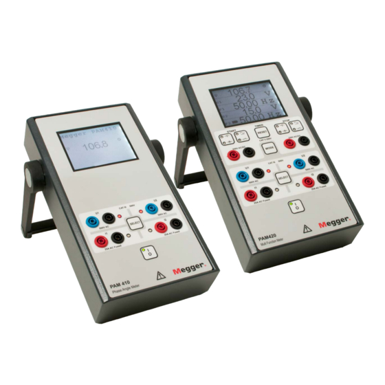
1 GENErAL General 1.1 Description 1.2 Mains and power PAM410 and 420 are specifically designed for Mains adapter measurements on electrical power systems. The phase angle is calculated from the relationship between two Model Skynet Electronic SNP-A02C power signals, either two currents or two voltages, or any combination. -
Page 7: Safety
Use a damp cloth for cleaning. Do not use liquid cleaners or aerosol cleaners. refer all servicing, including the exchange of fuses, to Megger authorized personnel. If you need to return the instrument, please use either the original crate or one of equivalent strength This equipment contains lithium batteries. -
Page 8: Panels
14 Button for switching instrument On/Off Detect voltage presence / Detect voltage absence or Top panel Closing contact / Open contact 15 Input for battery charger Button for selecting timer STOP condition: Voltage / Contact Pam410 panel PAM 410/420 ZP-BP02E BP0123CE... -
Page 9: Phase Angle Measurements
N-L1 and N-L2 Important Connect as follows: Read the manual and comply with the Safety instructions before using PAM410/420. L1 to input U1 (red) L2 to input U2 (red) Always comply with local safety regula- N to input U1 (black) N to input U2 (black) tions. -
Page 10: Phase Angle Between Voltages N-L1 And
4 PHASE ANGLE MEASUrEMENTS 4.3 Phase angle between 4.4 Phase angle between voltages N-L1 and L3-L2 voltages N-L1 and L2-L3 Connect as follows: Connect as follows: L1 to input U1 (red) L2 to input U2 (red) L1 to input U1 (red) L3 to input U2 (red) N to input U1 (black) L3 to input U2 (black) -
Page 11: Phase Angle Between Voltages L1-N And
4 PHASE ANGLE MEASUrEMENTS 4.5 Phase angle between 4.6 Phase angle between voltages L1-N and L3-L2 voltage N-L1 (U1) and current L1 (I2) Connect as follows: Connect as follows: L1 to input U1 (black) L2 to input U2 (red) N to input U1 (red) L3 to input U2 (black) L1 to input U1 (red) L1 to input I2 (red) -
Page 12: Secondary Testing Of Relay Protection Systems
4 PHASE ANGLE MEASUrEMENTS 4.7 Secondary testing of 4.8 Directional testing of relay protection systems relay protection systems At secondary testing of a relay protection to verify After installing the object, control the connections that the protection gives tripping in between given between test cut and measuring transformers through angle range can be done by using the phase angle directional testing with the help of the phase angle... -
Page 13: Timing (Pam420)
5 TIMING (PAM420) Timing (PAM420) 5.1 Activating using 5.2 Activating using voltage sense contact sense Detect voltage presence Closing contact Detect voltage absence Open contact Any combination of start and stop can be selected. The reset button sets the time to zero, and enables a new start. -
Page 14: Voltage, Current And Frequency Measurements (Pam420)
6 VOLTAGE, CUrrENT AND FrEqUENCY MEASUrEMENTS (PAM420) Voltage, current and frequency measurements (PAM420) Voltage Two currents – Measuring inputs I1+I2 Press SELECT button to activate the correct inputs. One voltage – Measuring input U1 Voltage – Current Measuring inputs I1+U2 Press SELECT button to activate the correct inputs. -
Page 15: Calibration
7 CALIBrATION Calibration 7.1 Standard calibration Calibration: 1.000 Equipment needed 499.2 ▪ Accurate DMM, e.g. bench multi meter e.g. Agilent 34401A or Fluke 8845 VSNS1: xxx VSNS2: XXX ▪ Synthesized voltage and current source Charging • Preferred 0-500 V AC, 0-25 A AC •... -
Page 16: Check Procedure After Calibration
7 CALIBrATION 7.2 Check procedure after 7.3 Timer calibration The timer functionality cannot be calibrated, only tested if within specifications. As the timer is using the same internal clock as the frequency measurement, Voltage it is suggested that the timer will show the correct Connect U1 to the voltage source time as long as the frequency measurement is within specifications. -
Page 17: Specifications
8 SPECIFICATIONS Specifications 8.1 Specifications *Current – Inputs I1 and I2 Measurement category CAT III 500 V PAM410/420 CAT IV 300 V Input range 0 – 25 A AC Specifications are valid at nominal input voltage and an ambient Inaccuracy 0.5% of reading... - Page 18 8 SPECIFICATIONS PAM 410/420 ZP-BP02E BP0123CE...
- Page 20 ▪ Insulation Power Factor (C&DF) Test Equipment worldwide. ▪ Insulation Resistance Test Equipment Megger is certified according to ISO 9001 and 14001. ▪ Line Testing Equipment Megger is a registered trademark. ▪ Low Resistance Ohmmeters Megger Group Limited ▪...
Need help?
Do you have a question about the PAM410 and is the answer not in the manual?
Questions and answers