Sign In
Upload
Download
Table of Contents
Contents
Add to my manuals
Delete from my manuals
Share
URL of this page:
HTML Link:
Bookmark this page
Add
Manual will be automatically added to "My Manuals"
Print this page
×
Bookmark added
×
Added to my manuals
Manuals
Brands
Megger Manuals
Measuring Instruments
TM1700 Series
User manual
Megger TM1700 Series User Manual
Circuit breaker analyzer
Hide thumbs
1
2
3
Table Of Contents
4
5
6
7
8
9
10
11
12
13
14
15
16
17
18
19
20
21
22
23
24
25
26
27
28
29
30
31
32
33
34
35
36
37
38
39
40
41
42
43
44
45
46
47
48
49
50
51
52
53
54
55
56
57
58
59
60
61
62
63
64
65
66
67
68
69
70
71
72
73
74
75
76
77
78
79
80
81
82
83
84
85
86
87
88
89
90
91
92
page
of
92
Go
/
92
Contents
Table of Contents
Troubleshooting
Bookmarks
Table of Contents
Table of Contents
Safety
General
Symbols on the Instrument
Safety Instructions
Protective Earthing Procedure in HV Environments
Introduction
General
Benefits
User's Registration
Service and Support
Contact Information
Checklist before Calling/E-Mailing for Support
Shipping
System Overview
The Instrument
Tm1710
Tm1720
Tm1750
Tm1760
TM1760 with 3 Extra Analogue Channels
Control Panel
Top Panel
Set Mode for DCM and Tune the System
How to Enter the Gis Mode
To Switch Back to Normal Mode
Tuning
External Equipment
Network/External Computer
Printer
Backup Media
External Screen
How to Activate the Svga Output
CABA Local
Start/Shut down CABA Local
Start
Shut down
Online Help
What´s this
Manual
Navigation & Display Buttons
Main and Submenus
Selected Items Bar
Repair CABA Local
Updating CABA Local
For Instrument with Built-In Screen
For Instrument Without Screen
Optional Software
Printer and Back-Up Media
Antivirus
The Main Menu
Templates
Breaker List
Breaker View
Analyser View
Transducers
System Settings
Templates Menu
What Is a Template
How to Create a Template
Max Config Template
Comparison to Test Plans in CABA Win
Create a Subfolder
Delete a Subfolder
Rename a Subfolder
Create a Template from a Breaker
Rename a Template
Set a Template as Default
Delete a Template
Breaker List Menu
Create a Breaker
Edit Breaker ID
Delete a Breaker
Import a Breaker
Export a Breaker
Begin a New Test
Edit Test ID
Delete a Test
Hook up Diagrams & Transducers
View a Recording
Graph
Parameters
Graph Layout
Display Settings
Print Preview
Delete Recording
Edit Notes
Breaker View Menu
Make Settings for a Breaker
Breaker Set up Example
Setting the Pulse and Delay Times
Setting the Measurement Preferences
Settings
Setting the Trig in Settings
Setting the Resistance Measurement Preferences
Setting the Measurement Time & Sample Interval
Motion Measurement Preferences Menu
Analyzer View Menu
Hook-Up Instructions
Select Transducer
Monitor
Transducers Menu
Define New Transducer
Defining Motion Transducer
Calibrating Resistive Transducers
System Settings Menu
General
DATE & Time
Company Data
Units
Printer
Select Printer
System Versions
Hardware Data
Backup/Restore
Perform Testing
TM1700 Start-Up
Check List - before Testing
Basic Test
Quick Test
Define a New Circuit Breaker
Using Circuit Breaker Created in CABA Win
Import Circuit Breaker Set-Ups from CABA Win
Reporting
Print Preview
Send Recordings to Other Report Formats
Evaluate the Results
Timing Measurement
Motion Measurement
Coil Currents
Dynamic Resistance Measurements (Drm)
Store Measurements
To Do Backup
Application Examples
Example 1
3-Phase Circuit Breaker with Single Interrupter Per Phase and Common Operating Mechanism
Example 2
3-Phase Circuit Breaker with Two Interrupters Per Phase and Separate Operating Mechanism
External Clamp-On CT Input
Coil Current Measurement
Individual Spring Charge Motor Current Measurements
Specifications
Specifications TM1700-Series
Troubleshooting & FAQ
Troubleshooting
FAQ - Frequently Asked Questions
Data Analysis
Analysis Window (Cabaana)
File Menu
Edit Menu
View Menu
Parameter Window
Graph Window
Layout Menu
Compare - Menu
Window Menu
Report
Quick Guide
Select - Connect - Inspect
Step 1: Select
Step 2: Connect
Step 3: Inspect
Index
Advertisement
Quick Links
1
Tm1720
2
Tm1710
3
Tm1760
4
Manual
Download this manual
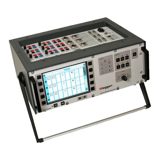
TM1700-series
Circuit Breaker Analyzer
User's Manual
Art No. ZP-BL16E
Doc. BL1448GE V06a
2017
Table of
Contents
Previous
Page
Next
Page
1
2
3
4
5
Advertisement
Table of Contents
Need help?
Do you have a question about the TM1700 Series and is the answer not in the manual?
Ask a question
Questions and answers
Related Manuals for Megger TM1700 Series
Measuring Instruments Megger TM1710 User Manual
Circuit breaker analyzer (92 pages)
Measuring Instruments Megger TM1720 User Manual
Circuit breaker analyzer (92 pages)
Measuring Instruments Megger TM1760 User Manual
Circuit breaker analyzer (92 pages)
Measuring Instruments Megger TDR1000/3 User Manual
Time domain reflectometers (28 pages)
Measuring Instruments Megger TDR500/3 User Manual
Time domain reflectometers (28 pages)
Measuring Instruments Megger TDR2000 User Manual
Time domain reflectometer (16 pages)
Measuring Instruments Megger TDR900 User Manual
Time domain reflectometer (16 pages)
Measuring Instruments Megger TDR2000/3 Quick Start Manual
(9 pages)
Measuring Instruments Megger TDR2000/3 User Manual
Time domain reflectometers (31 pages)
Measuring Instruments Megger TDR2000/3 User Manual
Time domain reflectometers (30 pages)
Measuring Instruments Megger TDR2000/3 Quick Start Manual
(8 pages)
Measuring Instruments Megger TDR2000/3 Quick Start Manual
(8 pages)
Measuring Instruments Megger Three-Phase TTR Instruction Manual
Transformer turns ratio test set. ttr330 series (70 pages)
Measuring Instruments Megger TTRU3 User Manual
True 30 transformer turns ratiometer (56 pages)
Measuring Instruments Megger TTRU1 User Manual
Handheld transformer turns ratiometer (52 pages)
Measuring Instruments Megger DLRO10HD User Manual
10 a digital low resistance ohmmeter (18 pages)
This manual is also suitable for:
Tm1710
Tm1720
Tm1750
Tm1760
Table of Contents
Print
Rename the bookmark
Delete bookmark?
Delete from my manuals?
Login
Sign In
OR
Sign in with Facebook
Sign in with Google
Upload manual
Upload from disk
Upload from URL


Need help?
Do you have a question about the TM1700 Series and is the answer not in the manual?
Questions and answers