
Related Manuals for Megger PQ2000


Summary of Contents for Megger PQ2000
- Page 1 MPQ2000-UG-EN Rev 8 October 2018 User Manual Megger MPQ2000 PQ Analyzer Valley Forge Corporate Center 2621 Van Buren Avenue Norristown, PA 19403-2329 U.S.A. 610-676-8500 www.megger.com...
- Page 3 MPQ2000 PQ Analyzer...
- Page 4 Specifications are subject to change without notice. WARRANTY Products supplied by Megger are warranted against defects in material and workmanship for a period of two years following shipment no other warranty. The warranty is void in the event of abuse (failure to follow recommended operating procedures) or failure by the customer to perform specific maintenance as indicated in this manual.
-
Page 5: Table Of Contents
Table of Contents 1 Introduction ................................. 1 2 Receiving Information ............................3 3 Overview of MPQ2000 ............................5 Applications ................................ 6 Definitions ................................7 Calculations ................................. 9 RMS Calculation: ............................. 9 Voltage and Current Waveform Data ......................9 ... - Page 6 Voltage and Current Connections ......................... 41 8 Wiring Diagrams for Demand Recording ...................... 43 Notes on Wiring Diagrams ..........................43 Floating Wye Neutral Measurement ......................57 Verify Active Setup File ..........................58 9 Starting and Stopping a Recording ........................59 ...
-
Page 7: Introduction
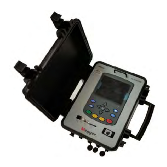
Introduction Thank you for your purchase of the Megger MPQ2000 PQ Power Analyzer. Be assured that your unit has been designed with emphasis on reliability, simplicity and ease of use. It will provide you with the information you need to investigate customer power quality complaints and compliance situations, verify billing, and pinpoint locations of high demand and power consumption. - Page 8 MPQ2000-UG-EN Rev 8 October 2018...
-
Page 9: Receiving Information
Examine the contents for damage received during transit. If any damage is discovered, file a claim with the carrier at once and notify Megger or its nearest authorized sales representative, giving a detailed description of the damage. MPQ2000-UG-EN Rev 8 October 2018... - Page 10 MPQ2000-UG-EN Rev 8 October 2018...
-
Page 11: Overview Of Mpq2000
Power Quality Software and uploading it to the Megger MPQ2000 Power Quality Analyzer. Each unit can store up to 90 user- defined setups. Should you need to change setups on site, you may select any of your programmed setups using the Power Analyzer’s front panel controls. -
Page 12: Applications
Kilovar hours, per phase and total system Kilovoltamp hours, per phase and total system Harmonic direction from source or load Harmonic magnitude and phase shift Up to 1000 out-of-limits events, with time stamp and duration Waveform capture using selectable triggers Frequency Trending IEC Flicker Trending THD Trending... -
Page 13: Definitions
Overview of MPQ2000 Definitions Class A A class of unit performance that complies with IEC standard 61000-4-30. Clock Hour A setup feature in the PQ software that when selected will delay Orientation the start of the recording until the real time clock in the PQ Device reaches a time interval that is a multiple of the selected storage interval. - Page 14 Post-Triggers A user selectable value in the setup file that defines the number of cycles the unit will record after a cycle has occurred that has exceeded the user programmed event limits. Power Factor The ratio of the total power input, in watts, to the total volt-ampere input to the converter.
-
Page 15: Calculations
Overview of MPQ2000 A sudden non-power frequency change in the steady state Transient condition of voltage or current. Vars A unit which is the imaginary counterpart of the watt. The relationship between a VAR and a watt in an alternating-current electrical system is determined by the power factor. -
Page 16: Rapid Voltage Changes: Under-Deviation Assessment And Over-Deviation Assessment
Rapid Voltage Changes: Under-Deviation Assessment and Over- Deviation Assessment: Voltage Unbalance: The negative sequence component u2 is evaluated by the following ratio, expressed as a percentage: For 3-phase systems, this can be written (with Uij fund = phase i to phase j fundamental voltage): The zero-sequence u0 component is evaluated by the magnitude of the following ratio, expressed as a percentage:... -
Page 17: Current Unbalance
Overview of MPQ2000 Current Unbalance: Power: Instantaneous Power (W) = V sample * I sample Active Power (P) = V* I * cos θ Reactive Power (VAR) = V* I * sin θ Apparent Power (S) (VA) = S = VI DPF = cos θ... - Page 18 MPQ2000-UG-EN Rev 8 October 2018...
-
Page 19: Mpq2000 Specifications
MPQ2000 Specifications Specifications reference 25ºC (77ºF) Transient Sampling Rate 1MHz RMS Sampling Rate 256 per cycle per channel, simultaneous RMS Aggregation 10 cycle at 50Hz / 12 cycle at 60Hz RMS Event Aggregation 1/2 Cycle Sliding Window VOLTAGE Voltage Input Channels Voltage Range 0-1000VAC / 0-1000VDC Voltage Resolution... - Page 20 90-600V 50Hz, 60Hz or 105-600V DC Auxiliary Input 120/240 V, 50/60 Hz Power Draw 49W Max BATTERY Battery Type 10.8VDC NiMH (Use only Megger Battery) Run Through Time 6.5 Hours Minimum without CT’s Charge Time 3 Hours MEMORY Memory Type...
- Page 21 MPQ2000 Specifications PHYSICAL Communications USB & Ethernet Weight 4.31kg (9.5lbs) Max Size 305mm x 266mm x 143mm (12.01 x 10.47 x 5.63 in.) ENVIRONMENTAL Operating Temperature -20° C to 50° C (-4° F to 122° F)* Storage Temperature -30° C to 60° C (-22° F to +140° F) Humidity 95% NC IP Rating...
- Page 22 MPQ2000-UG-EN Rev 8 October 2018...
-
Page 23: Safety
Safety Warnings and Safety Precautions WARNING! Death, serious injury, or fire hazard could result from improper use/installation of this instrument. Read and understand this manual before installing this instrument. Installation of this instrument MUST be performed in compliance with the National Electric Code and any additional safety requirements applicable to your installation. - Page 24 WARNING! The equipment should not be used if there is any visible damage to the case or if the hardware holding the unit together has been loosened. MPQ2000-UG-EN Rev 8 October 2018...
-
Page 25: Mpq2000 Operation
MPQ2000 Operation The following section describes the operation of the MPQ2000 unit. This section will describe in a step by step manner how to setup, program, install and download data from the MPQ2000. Connector Layout / Interconnect Voltage Channel Voltage Channel Voltage Channel Voltage Channel Phase A... -
Page 26: Front Panel Keypad Operation
Front Panel Keypad Operation Left, Up, Enter, Right and Down Back Home Analyze Help Scope Power Record Status Indicator Flashing Green = Booting Up AUX/VA Power Switch Solid Green = Normal Operation Amber Light = Low Battery Flashing Red Light = Error MPQ2000-UG-EN Rev 8 October 2018... -
Page 27: Menu Flow Charts
MPQ2000 Operation Menu Flow Charts DMM Screen MPQ2000-UG-EN Rev 8 October 2018... - Page 28 DMM Mode MPQ2000-UG-EN Rev 8 October 2018...
-
Page 29: Dmm Mode
MPQ2000 Operation DMM Mode The MPQ2000 has a real time multi-meter mode. In this mode the analyzer will display real time voltages, currents, THD, power, phases, unbalance, harmonics and flicker. The DMM screen will open when the analyzer first powers up. The DMM screen can also be opened by pressing the DMM short cut key. - Page 30 2. The POWER screen. This screen will display Real Power, Reactive Power, Apparent Power, Displacement Power Factor and True Power Factor. 3. The UNBALANCE screen. This screen will display the Negative Sequence Unbalance and The Zero Sequence Unbalance. MPQ2000-UG-EN Rev 8 October 2018...
- Page 31 MPQ2000 Operation 4. The HARMONICS screen. This screen will display the Magnitude of the Harmonic Orders. Use the UP / DOWN arrows to scroll through the harmonic orders. 5. The FLICKER screen. This screen will display the Instantaneous Flicker and the 1 Minute Flicker Interval. Note: This screen must be left on for at least 1 minute in order to view the flicker 1 minute interval.
-
Page 32: Scope Mode
Scope Mode The MPQ2000 has a real time scope mode. In this mode the analyzer will display voltages and current waveforms, unbalance vectors, harmonics, inter-harmonics and harmonic direction. The SCOPE screen can also be opened by pressing the SCOPE short cut key. The SCOPE screen consists of 3 different screens. - Page 33 MPQ2000 Operation NOTE: The bottom of the screen will display the key functions of the analyzer for each screen. 2. The UNBALANCE screen. This screen will display Voltages, Currents, Phase Angles, Negative Sequence Unbalance, Zero Sequence Unbalance and a Vector Diagram of the Angles. Use the UP / DOWN arrow keys to toggle between IEC Unbalance and ANSI Unbalance.
-
Page 34: Configuring The Mpq Unit
Use the UP / DOWN keys to scroll through the different channels and to view the harmonic direction. Configuring the MPQ Unit Prior to first use the MPQ Unit needs to be configured. This allows the operator to set the date and time format as well as any operator preferences. NOTE: If these settings are not made then the date and times in the recordings may be incorrect. - Page 35 MPQ2000 Operation 2. Select DATE/TIME then press the ENTER key. 3. Use the UP / DOWN & ENTER keys to scroll down and select the desired date and time formats. 4. Use the UP / DOWN keys to scroll down to TIME ZONE then press the ...
-
Page 36: Configure Unit Preferences
Configure unit preferences 1. From the HOME screen select SETUP then press the ENTER key. 2. Select PREFERENCES then press the ENTER key. MPQ2000-UG-EN Rev 8 October 2018... - Page 37 MPQ2000 Operation 3. Use the UP / DOWN & ENTER keys to scroll down and select the desired selections. From this screen the user can select the following: 1. Change the Voltage and Current Trace colors. (These can be matched to local standards) 2.
-
Page 38: Importing / Activating A Setup File
A setup file is used to program the unit to perform different types of recording. Multiple setup files can be installed into the unit. These setup files can be activated from the front panel of the unit or using the Megger PQ software. Uploading a setup file from the PC See the MEGGERPQ Manual. - Page 39 MPQ2000 Operation 5. Scroll down to IMPORT SETUP FROM USB on the USB Memory screen and press the ENTER key. This will display the setup files on the USB stick. 6. Use the UP / DOWN keys to scroll to the desired setup file and press the ...
-
Page 40: Uploading A Setup File From The Sd Card
Uploading a Setup File from the SD Card 1. Verify the batteries in the unit are fully charged or plug the unit into an AC source. 2. Power up the MPQ2000 PQ Analyzer and go to the MAIN Menu. 3. Plug the SD card into the MPQ2000 SD Card slot. ... -
Page 41: Activating The Imported Setup File
MPQ2000 Operation Activating the Imported Setup File 1. Return to the MAIN MENU 2. Scroll down to SETUP on the MAIN Menu and press the ENTER key. This will display the Setup Files screen. 3. Scroll down to SELECT on the Setup Files screen and press the ENTER key. -
Page 42: Renaming A Data Or Setup File
Renaming a Data or Setup File When renaming a Setup File start at the Select Setup File Screen on the unit. HOME / SETUP / SELECT When renaming a Data File start at the Select Data File screen on the unit. HOME / VIEW DATA 1. - Page 43 MPQ2000 Operation 3. Using the UP / DOWN /◄ LEFT /► RIGHT keys navigate to the desired letter / number. 4. Press the ENTER key until the desired letter / number is displayed. 5. When the desired name is created scroll over the ACCEPT and press the ...
- Page 44 To backspace, use the "<" symbol. To enter a dot ".", dash "-", or underscore "_" , use the "1" key No spaces are allowed in the file names. MPQ2000-UG-EN Rev 8 October 2018...
-
Page 45: Installing The Mpq2000 Pq Analyzer
Installing the MPQ2000 PQ Analyzer WARNING! Be sure to use all appropriate safety equipment when installing the MPQ2000 PQ Analyzer. Failure to do so can result in injury or death. WARNING! Inspect all power cords and wires for proper insulation integrity before connecting to any power source. -
Page 46: Battery
Battery Battery Charging Always ensure that the battery is properly charged. It must maintain a 12-volt minimum for proper recording operation. A battery charge indicator on the MPQ2000 display allows you to view the batteries state of charge. NOTE: The battery should be charged prior to recording with the unit powered off. Charging the MPQ2000 Battery The MPQ2000 battery will charge when the unit is powered off of either Phase A or when the unit is powered off of the auxiliary power. -
Page 47: Voltage And Current Connections
NOTE: Current probes not purchased from Megger require Megger adapters. To install the Power Analyzer using current clamps, plug the selected clamps into the current input connectors (labeled IA, IB, IC, and IN) then clamp around the source to be measured. - Page 48 MPQ2000-UG-EN Rev 8 October 2018...
-
Page 49: Wiring Diagrams For Demand Recording
Wiring Diagrams for Demand Recording Notes on Wiring Diagrams 1. The Power Analyzer records all voltages and currents that are hooked up providing you have activated channels in the setup. Even though not all channels may be required for the power configurations on the following pages, you can connect them to obtain voltage/current recordings, providing you activate the channel. - Page 50 LOAD 2-WIRE SINGLE PHASE SINGLE WATTMETER ROTATION MPQ2000-UG-EN Rev 8 October 2018...
- Page 51 Wiring Diagrams for Demand Recording LOAD 3-WIRE SINGLE PHASE RESIDENTIAL METER ROTATION MPQ2000-UG-EN Rev 8 October 2018...
- Page 52 LOAD 3-WIRE DELTA CONNECTION 2- WATTMETER METHOD MPQ2000-UG-EN Rev 8 October 2018...
- Page 53 Wiring Diagrams for Demand Recording LOAD 3-WIRE SPLIT PHASE 2- WATTMETER METHOD ROTATION MPQ2000-UG-EN Rev 8 October 2018...
- Page 54 LOAD 3-WIRE NETWORK METER ROTATION ROTATION MPQ2000-UG-EN Rev 8 October 2018...
- Page 55 Wiring Diagrams for Demand Recording LOAD 3-WIRE OPEN DELTA 2-WATTMETER METHOD ROTATION ROTATION AC-BA-CB AC-CB-BA MPQ2000-UG-EN Rev 8 October 2018...
- Page 56 LOAD 3-WIRE WYE CONNECTION 2-WATTMETER METHOD ROTATION ROTATION MPQ2000-UG-EN Rev 8 October 2018...
- Page 57 Wiring Diagrams for Demand Recording LOAD 4-WIRE RED-LEG OPEN DELTA 3-WATTMETER METHOD ROTATION ROTATION AC-BA-CB AC-CB-BA MPQ2000-UG-EN Rev 8 October 2018...
- Page 58 LOAD 4-WIRE RED-LEG DELTA 3-WATTMETER METHOD ROTATION ROTATION AC-BA-CB AC-CB-BA MPQ2000-UG-EN Rev 8 October 2018...
- Page 59 Wiring Diagrams for Demand Recording LOAD 4-WIRE WYE CONNECTION 3-WATTMETER METHOD ROTATION ROTATION MPQ2000-UG-EN Rev 8 October 2018...
- Page 60 LOAD 4-WIRE WYE CONNECTION 2½- WATTMETER METHOD ROTATION ROTATION MPQ2000-UG-EN Rev 8 October 2018...
- Page 61 Wiring Diagrams for Demand Recording LOAD 4-WIRE RED-LEG OPEN DELTA 2½-WATTMETER METHOD ROTATION ROTATION AC-BA-CB AC-CB-BA MPQ2000-UG-EN Rev 8 October 2018...
- Page 62 LOAD 4-WIRE RED-LEG DELTA 2½-WATTMETER METHOD ROTATION ROTATION AC-BA-CB AC-CB-BA MPQ2000-UG-EN Rev 8 October 2018...
-
Page 63: Floating Wye Neutral Measurement
Wiring Diagrams for Demand Recording Floating Wye Neutral Measurement LOAD FLOATING WYE CONNECTION 4-WIRE WYE CONNECTION 3-WATTMETER METHOD MPQ2000-UG-EN Rev 8 October 2018... -
Page 64: Verify Active Setup File
Verify Active Setup File 1. From the Main Menu scroll down to SETUP and press the ENTER key. 2. This will take you to the SETUP menu. Scroll down to SELECT and press the ENTER key. The active Setup File will have an asterisk in front. MPQ2000-UG-EN Rev 8 October 2018... -
Page 65: Starting And Stopping A Recording
Starting and Stopping a Recording Before starting a recording is best to verify the current clamps are set to the proper range and the analyzer is connected properly. Verify the Input Connections Before starting any test, verify that you have hooked up all the inputs required for the active setup program. -
Page 66: Starting A Recording
Starting a Recording Once the connections are verified, press the RECORD button to start the recording. The analyzer will verify the inputs and settings before starting the recording. The analyzer will verify the following: The default frequency is correct. ... - Page 67 Starting and Stopping a Recording The operator has the option to do the following: Manually change the range on the CT to the correct range. Have the analyzer automatically change the range in the setup file to match the range setting on the CT.
- Page 68 During the recording the mode the analyzer does not display scope mode functions. The user can use the arrows to scroll over to POWER to view the power and energy parameters during the recording. To stop the recording, press the RECORD key again. If the display on the analyzer is off, pressing the RECORD key will first turn on the display.
-
Page 69: Downloading Data From The Mpq2000
Downloading Data from the MPQ2000 The data from the MPQ2000 can be retrieved in several different manners. The data can be transferred through the type B USB Port directly to the PC. The data can be transferred through the Ethernet Port directly to the PC. ... - Page 70 4. From the SD CARD scroll down to EXPORT TEST DATA TO USB and then press the ENTER key. 5. Select EXPORT ALL TEST DATA then press the ENTER key. The data transfer will now begin. 6. Once the data is transferred a success message shall appear. NOTE: See MPQ-SWG-EN manual for transferring data from the USB stick or the SD card to the PC.
-
Page 71: Viewing Data On The Mpq Pq Analyzer
Viewing Data on the MPQ PQ Analyzer The MPQ PQ Analyzer will display the recorded data on the units display. The MPQ Analyzer will trend the following data. RMS Voltage and Current Power Energy Power Factor ... -
Page 72: Viewing An Rms Chart
Viewing an RMS Chart Starting from the HOME Screen (Press to open the HOME Screen): 1. Use the UP / DOWN to navigate through the menu options. 2. Press the ENTER key to select an option. Select VIEW DATA Select Data File Select type of RMS chart then View RMS... - Page 73 Viewing Data on the MPQ PQ Analyzer Trace colors Displayed Phase Scale in Amps Scale in volts Start date and Trace end time date and time Zoom / Scan: Press the Select Function: Use SIDE to ENTER key to enter zoom SIDE arrows to select different mode and use the scan line.
-
Page 74: Viewing A Unbalance Chart
Viewing a Unbalance Chart Starting from the HOME Screen (Press to open the HOME Screen): 1. Use the UP / DOWN to navigate through the menu options. 2. Press the ENTER key to select an option. Select Data File Select VIEW DATA Select UNBALANCE then press ENTER View Unbalance Chart... - Page 75 Viewing Data on the MPQ PQ Analyzer Trace colors Displayed Sequence Factor Scale in percent of fundamental Trace end Start date and date and time time Select Function: Use SIDE to Select Phases: Use UP / Zoom / Scan: Press the SIDE arrows to select different DOWN arrows to select ENTER key to enter zoom...
-
Page 76: Viewing A Power Or Energy Chart
Viewing a Power or Energy Chart Starting from the HOME Screen (Press to open the HOME Screen): 1. Use the UP / DOWN to navigate through the menu options. 2. Press the ENTER key to select an option. Select VIEW DATA Select Data File View POWER CHART... - Page 77 Viewing Data on the MPQ PQ Analyzer Trace colors Displayed Sequence Factor Scale in KW / KVA & Start date and Trace end time date and time Select Function: Use SIDE to Select Phases: Use UP / Zoom / Scan: Press the SIDE arrows to select different DOWN arrows to select ENTER key to enter zoom...
-
Page 78: Viewing A Thd Chart
Viewing a THD Chart Starting from the HOME Screen (Press to open the HOME Screen): 1. Use the UP / DOWN to navigate through the menu options. 2. Press the ENTER key to select an option. Select VIEW DATA Select Data File Select THD then press ENTER to View THD CHART... - Page 79 Viewing Data on the MPQ PQ Analyzer Trace colors Displayed Phase Scale in percent of fundamental Start date and Trace end time date and time Select Function: Use SIDE to Select Phases: Use UP / Zoom / Scan: Press the SIDE arrows to select different DOWN arrows to select ENTER key to enter zoom...
-
Page 80: Viewing A Frequency Chart
Viewing a Frequency Chart Starting from the HOME Screen (Press to open the HOME Screen): 1. Use the UP / DOWN to navigate through the menu options. 2. Press the ENTER key to select an option. Select VIEW DATA Select Data File Select Frequency then press ENTER to View FREQUENCY CHART... - Page 81 Viewing Data on the MPQ PQ Analyzer Scale in Hertz Start date and time Trace end date and time Zoom / Scan: Press the Select Function: Use SIDE to ENTER key to enter zoom SIDE arrows to select different mode and use the scan line. charts.
-
Page 82: Viewing A Harmonics / Inter-Harmonics Chart
Viewing a Harmonics / Inter-Harmonics Chart Starting from the HOME Screen (Press to open the HOME Screen): 1. Use the UP / DOWN to navigate through the menu options. 2. Press the ENTER key to select an option. Select VIEW DATA Select Data File Select harmonic sequence then press... - Page 83 Viewing Data on the MPQ PQ Analyzer Trace colors Displayed Phase Scale in percent of fundamental Start date and Trace end time date and time Select Function: Use SIDE to Select Phases: Use UP / Zoom / Scan: Press the SIDE arrows to select different DOWN arrows to select ENTER key to enter zoom...
-
Page 84: Viewing A Flicker Chart
Viewing a Flicker Chart Starting from the HOME Screen (Press to open the HOME Screen): 1. Use the UP / DOWN to navigate through the menu options. 2. Press the ENTER key to select an option. Select VIEW DATA Select Data File Select Short Term or Long Term then Select Flicker... - Page 85 Viewing Data on the MPQ PQ Analyzer Trace colors Displayed Phase Scale in percent of fundamental Start date and Trace end time date and time Select Function: Use SIDE to Select Phases: Use UP / Zoom / Scan: Press the SIDE arrows to select different DOWN arrows to select ENTER key to enter zoom...
-
Page 86: Viewing An Event Chart
Viewing an Event Chart Starting from the HOME Screen (Press to open the HOME Screen): 1. Use the UP / DOWN to navigate through the menu options. 2. Press the ENTER key to select an option. Select VIEW DATA Select Data File Select type of event using the side to side Select Events... - Page 87 Viewing Data on the MPQ PQ Analyzer Select the date the event occurred. Select Event then press ENTER to create chart. Start Date and Channel Event Time Event Event Number Duration Scale Minimum, in volts Maximum and Average amps values recoded during the event.
- Page 88 MPQ2000-UG-EN Rev 8 October 2018...
-
Page 89: Unit Maintenance
Unit Maintenance CAUTION Have maintenance performed only by qualified service personnel. Cleaning Unit Display: Clean the display using either a clean dry lint free cloth or a lens cleaner. MPQ2000 Unit: Do not clean with anything more than a clean dry cloth. Resetting the MPQ2000 Should the MPQ2000 unit ever stop responding to key strokes or the display should ever freeze the unit can be reset by Depressing and holding the Power ON / OFF... -
Page 90: Battery Replacement
Battery Replacement The following procedure should be followed when replacing the MPQ2000 battery: 1. If the unit is on, turn the unit off by pressing and releasing the ON/OFF button. 2. Disconnect the unit from AC power, if connected. 3. Remove the door of the unit, placing it at a 60 degree angle and sliding it up and off its hinges. - Page 91 Unit Maintenance 5. Carefully lift on the front panel handle to lift the front panel from its enclosure, as shown below. (Do not pass 90 degrees. If so, the current PCB ribbon cable will disconnect.) 6. Remove the 3 screws holding the battery cover in place. 7.
- Page 92 11. Replace the battery cover and secure with the 3 screws. 12. Carefully place the front panel back into the enclosure. Be sure not to pinch any wires. 13. Install the four screws that secure the front panel to the enclosure. 14.
-
Page 93: Spare Parts
Spare Parts Part No. Description 2008-369 Battery Pack JA1009 Current Connector Dust Covers MPQ2000-UG-EN Rev 8 October 2018... - Page 94 MPQ2000-UG-EN Rev 8 October 2018...
Need help?
Do you have a question about the PQ2000 and is the answer not in the manual?
Questions and answers