
Related Manuals for Megger PCA2


Summary of Contents for Megger PCA2
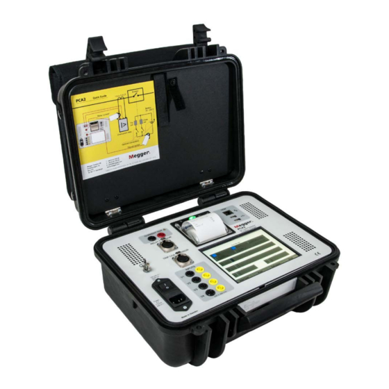
- Page 1 PCA2 On-Load Protection Condition Analyser User’s Manual Art No. ZP-CQ01E Doc. CQ0033CE 2013...
- Page 3 © 2013, Megger Sweden AB. All rights reserved. The contents of this manual are the property of Megger Sweden AB. No part of this work may be reproduced or transmitted in any form or by any means, except as permitted in written license agreement with Megger Sweden AB. Megger Sweden AB has made every reasonable attempt to ensure the completeness and accuracy of this document.
-
Page 4: Table Of Contents
Probe DC offset ............37 Index ............38 2.3 Unpack system ...........11 Packing list ..............11 3 Panel ............ 12 The PCA2 display ............. 13 Printer setting ............13 4 System settings and configuration ..14 4.1 System mode ..........14 Zero DC ..............14 User defaults ............. - Page 5 CQ0033CE ZP-CQ01E PCA2...
-
Page 6: Safety
▪ When testing current transformer. Dangerous voltages can appear in the secondary circuits if they are open. ▪ Unplug PCA2 from the mains supply when it is left unattended or not in use. PCA2 ZP-CQ01E CQ0033CE... - Page 7 5. Separate ground wire 9. Cables ▪ ▪ The PCA2 case must also be grounded by the separate Use only approved mains detachable cable set with protective ground wire with connection to the PCA2. Main supply cables shall be rated for the Protective Conductor Terminal on top of the PCA2.
- Page 8 18. Returning it from overheating. These openings must not be blocked nor covered during operation. ▪ If, for some reason, you need to return PCA2, please use either the original transport box or one of 13. Lightning equivalent strength ▪...
- Page 9 1 SAFETy CQ0033CE ZP-CQ01E PCA2...
-
Page 10: Introduction
The PCA2 can be used to perform many different or repair by any person, company or corporation not types of tests: authorized by Megger. -
Page 11: Service/Technical Support
2.3 Unpack system For technical assistance please contact your local Unpack the unit and check for evidence of any ship- representative or direct your request to Megger in ping damage. If there is any visual damage, imme- Sweden. diately notify the freight carrier to make a damage claim, and notify Megger of the damage. -
Page 12: Panel
USB ports and used for transferring results to a PC. The Ethernet (network) port is not currently utilised. ▪ Fuses 2 x T 6.3 A, 250 V AC ▪ Mains inlet ▪ ON/OFF switch PCA2 ZP-CQ01E CQ0033CE... -
Page 13: The Pca2 Display
3 PANEL The PCA2 display Set the PCA2 ON/OFF switch to OFF. Touch and hold the Print button while you switch to ON. The PRINTER SETUP printout comes out. Now release the button. The value of a particular menu item can be set or changed by a quick touch on the Print button. -
Page 14: System Settings And Configuration
Here you can add and edit the test details. Touch "User Defults". PCA config Touch "Add" for new items Touch "PCA Config". Touch an item to edit and then touch "Edit". Make your settings. Touch "Ok" or "Cancel" to return to the start screen. PCA2 ZP-CQ01E CQ0033CE... -
Page 15: Help
By double touching any of the lines "Fre- quency" or "Examine Load" an new window appears and you can make the desired set- tings. Touch "OK" to return. Help The "help" button is alwys available. Touch "Help" to invoke the User guide". CQ0033CE ZP-CQ01E PCA2... -
Page 16: On-Load Current Injection - Principle Of Operation
▪ The D/A controls the power booster/amplifier which outputs a voltage to the Current Out terminals. ▪ Current flowing into the Relay is then measured with the external clip-on current sensor (Irly). PCA2 ZP-CQ01E CQ0033CE... -
Page 17: Examining Load Stage
5 ON-LOAD CURRENT INjECTION - PRINCIPLE OF OPERATION 5.2 Examining load stage 'Examine Load' refers to the method by which the PCA2 current-source sense usees two different modes to generate. If 'Updated' is selected (recommended) – The cur- rent injection is dynamically corrected while injecting current. -
Page 18: Connections For Auto Or Manual Testing
However, the displayed waveform will always follow the arrow marked on the current sensors so that relative current polarities/phase angles can be measured on the PCA2 display. PCA2 ZP-CQ01E CQ0033CE... -
Page 19: Optional Connections
6 CONNECTIONS FOR AUTO OR MANUAL TESTING 6.2 Optional connections Additional connections can be made from the other unused PCA2 inputs to various points on a breaker/protection panel: Itc ( ) for recording the trip-coil TRIP COIL I SENSOR current profile. -
Page 20: Manual Test Mode
"9. Functional Check Procedure" can be used in the absence of a real load. Manual mode is the mode the PCA2 first enters when powered up and after the “Please check all Cur- Select the current to inject for the test using rent...”... - Page 21 8 AUTO TEST MODE CQ0033CE ZP-CQ01E PCA2...
-
Page 22: Auto Test Mode
"Stop Inj On Change"). tion. Select the "Current to Inject (Amps)" value. This is typically set to a multiple of the relay plug setting. Select the "Set Fault (Injection)Time" (i.e. max length of injection). The fault time PCA2 ZP-CQ01E CQ0033CE... -
Page 23: Auto Test Mode - Calculator
• the maximum time to inject for. In practice it is often Prefault defines how long the PCA2 will record before desired to inject the relay at a multiple of its plug set- the injection/fault. -
Page 24: Auto Test Mode - Interpretation Of Graphical Results/Measurements
Main parts of the automatic test display The following are of interest: 1. Load current collapses (when the breaker trips) 2. Injected current from the PCA2 to the relay 3. Contact closes (connected to the relay trip contact, can also usefully be connected to trip supply battery, etc.) - Page 25 Also the battery voltage has been con- These COMTRADE records can be copied nected to V1, permitting any dip during a test to be from the PCA2 onto a USB stick using the file observed and quantified. manager (see later).
-
Page 26: Auto Test Mode - Auto Test Analysis
Touch the "Graph Result" button to show the graphical results. You can adjust the text result value by touch- ing the the value or name. The "Graph Result" view will appear. Touch the thin vertical line (cursor) and move as desired. PCA2 ZP-CQ01E CQ0033CE... - Page 27 Max I_tc during entire test Initial battery Voltage on V1 input voltage just before TRLy VMIN Minimum battery Minimum voltage on voltage V1 during entire test Auto test results with auto TRLY analysis markers shown. ACON LTCH MCON CQ0033CE ZP-CQ01E PCA2...
-
Page 28: Handling Results / File Manager
Then click the copy or move button. (Please note: large files may take some time to copy). Changing directories To change directories double click on the directory name. Double click on “..” to return to the parent directory. PCA2 ZP-CQ01E CQ0033CE... -
Page 29: Pc Viewer Software
The software is easy to use and there are instructions as well. Extract the files from the zipped folder "PCA Viewer". Run the file "PCAViewer.exe CQ0033CE ZP-CQ01E PCA2... -
Page 30: Functional Check Procedure
The following describes a quick functional check to briefly indicate "Examining Load") and then proceed to start the injection. test the main functions of the PCA2. This test should be performed whenever it is desired to check the The display will show a 1 A sinewave (default initial Manual Test current value) for both proper functioning of the PCA2. - Page 31 11 SPECIFICATIONS CQ0033CE ZP-CQ01E PCA2...
-
Page 32: Specifications
11 SPECIFICATIONS Specifications Specifications PCA2 Current output Fully software controlled and regulated. Specifications are subject to change without notice. Injection start synchronised with zero crossing and data record- Environment ing. During ON-LOAD injections automatically phase-locks (45-65 Hz) and instantly corrects for any load current variation during... - Page 33 10,000 samples/sec (±0.1msec resolution) sampling rate Memory 32 Mb memory dedicated to waveform/ event acquisition (40 seconds recording for all channels at 10 kHz) Trigger events Programmable; start & stop recording on any or multiple Voltage/Contact/Current inputs or injection start/stop CQ0033CE ZP-CQ01E PCA2...
-
Page 34: A1 Glossary
.HDR file to hold test data and the results of any auto- matic analysis on the data. So each PCA result consists of three files (.CFG, .DAT & .HDR), all of which must be copied and stored together. PCA2 ZP-CQ01E CQ0033CE... - Page 35 A2 USING ADDITIONAL CURRENT PROBES CQ0033CE ZP-CQ01E PCA2...
-
Page 36: A2 Using Additional Current Probes
Using additional current probes Additional current probes can be connected to the PCA2 to allow it to monitor extra currents during an injection. This is useful as it allows, for example, three phases to be monitored while injecting into one of them. -
Page 37: Probe Dc Offset
A2 USING ADDITIONAL CURRENT PROBES Probe DC offset Note that Hall-Effect current probes (as used on the PCA2) always have an inherent DC offset present which varies with temperature. For this reason it is recommended to regularly re-zero the inputs. -
Page 38: Index
Glossary ............34 Graphical results..........24 Handling results ..........28 Injections ............20 Interpretation of graphical results ....24 Load stage ............. 17 Manual test mode .......... 20 On-Load current injection ......16 Optional connections ........19 PCA2 ZP-CQ01E CQ0033CE... - Page 39 INDEX CQ0033CE ZP-CQ01E PCA2...
- Page 40 Megger is uniquely placed to meet the ▪ Insulation Power Factor (C&DF) Test Equipment needs of its customers worldwide. ▪ Insulation Resistance Test Equipment Megger is certified according to ISO 9001 and 14001. ▪ Line Testing Equipment Megger is a registered trademark. ▪ Low Resistance Ohmmeters Megger Group Limited ▪...
Need help?
Do you have a question about the PCA2 and is the answer not in the manual?
Questions and answers