Sekonic LITEMASTER PRO L-478 Series Operating Manual
Light meter
Hide thumbs
Also See for LITEMASTER PRO L-478 Series:
- Startup manual (4 pages) ,
- Operating manual (68 pages)
Table of Contents
Advertisement
Quick Links
Find Quality Products Online at:
Operating Manual
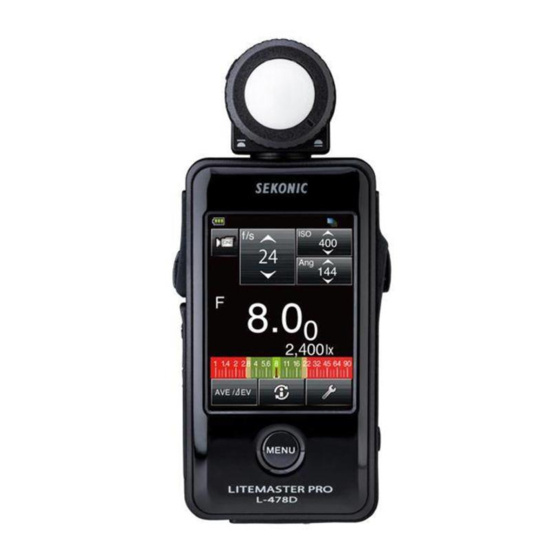
LITEMASTER PRO
L-478 Series
This manual is for common operation between L-478 Series.
Refer to each L-478DR Series, L-478DR-EL Series or
L-478DR-PX Series manual for speci c radio operations.
Please read the operating manual and safety precaution carefully
to fully understand the features of this product before use and
keep it for future use. Keep the operating manual in a safe place.
GlobalTestSupply
www.
Light Meter
.com
sales@GlobalTestSupply.com
Advertisement
Table of Contents

Related Manuals for Sekonic LITEMASTER PRO L-478 Series


Summary of Contents for Sekonic LITEMASTER PRO L-478 Series
- Page 1 Light Meter Operating Manual LITEMASTER PRO L-478 Series This manual is for common operation between L-478 Series. Refer to each L-478DR Series, L-478DR-EL Series or L-478DR-PX Series manual for speci c radio operations. Please read the operating manual and safety precaution carefully to fully understand the features of this product before use and keep it for future use.
- Page 2 The LITEMASTER PRO L-478 Series (referred to as L-478 Series from here on) comes with “Camera exposure profile” to offer today’s digital and film shooter with repeatable precision, accurate measurement and digital exposure control.
- Page 3 • The contents of this manual may be subject to change for the product’s specification modifications and other reasons without prior notice. We recommend that you download the latest operating manual to use this product. • The safety-related precautions such as «Safety Guide and Maintenance» and «Safety Precautions» conform to the legal and industry standards that were applicable at the time this operating manual was created.
-
Page 4: Accompanying Accessories
Accompanying Accessories The following items are included with the meter in the package. Please be sure to check that all noted items are included. * If any items are missing, please contact the distributor or the reseller you purchased the meter from. * The USB cable (that has the A connector and Mini-B connector) is not included in the package. -
Page 5: Safety Precautions
Safety Precautions Before using this product, please read this “Safety Precautions” for proper operation. The warning symbol indicates the possibility of death or serious injury if the product is not used properly. The caution symbol indicates the possibility of minor to moderate personal injury or product damage if the product is not used properly. -
Page 6: Table Of Contents
Table of Contents Accompanying Accessories ............. 4 Safety Precautions ................5 Parts Designations ................9 1-1. Parts Designations ............... 9 Before Using ..................10 2-1. Attaching the Strap ..............10 2-2. Inserting the Batteries ..............10 2-3. Power ON/OFF ................11 2-4. - Page 7 Table of Contents 5-2. Measuring in Flash Light Mode ..........34 5-2-1. Cord (PC) Flash Mode ............. 35 5-2-2. Cordless Flash Mode ............ 36 5-2-3. Cord Multi (Cumulative) Flash Mode ....... 37 5-2-4. Cordless Multiple (Cumulative) Flash Mode ......38 5-3. Out of Displayed Range or Measuring Range ......39 5-3-1.
- Page 8 Table of Contents Optional Accessories (Sold Separately) .......... 62 Registered Filters ................63 Specifications ..................64 Safety Guide and Maintenance ............66 Troubleshooting ................67 GlobalTestSupply www. .com Find Quality Products Online at: sales@GlobalTestSupply.com...
-
Page 9: Parts Designations
Parts Designations 1-1. Parts Designations Front View Rear View Bottom View Strap Lock lever Lumisphere eyelet retracting ring Measuring Lumisphere Synchro terminal button * Memory button* Battery Cover Open Battery Touch panel cover latch USB port Power button Battery Menu button compartment Battery cover The following table lists the functions of each part. -
Page 10: Before Using
Before Using 2-1. Attaching the Strap 1) Pass the strap included through the outer hole of the Strap eyelet 2) Pass the opposite end of the strap through the loop at the end of strap. • Infants or toddlers may accidentally wrap the strap around their neck, so please place it in a location out of their reach. -
Page 11: Power On/Off
• Please wait 3 seconds between repeated power on and power off sessions. • Directly after replacing the batteries, a white screen with the SEKONIC logo in blue will be displayed, followed by the appropriate Startup screen above. • An L-478 Series memory check is being executed while the blue bar graph is moving when the Logo screen is displayed, so please do not turn OFF the power, as doing so may cause damage. -
Page 12: Checking The Battery Capacity
2-4. Checking the Battery Capacity When the power is turned on, the battery power indicator is displayed at the upper left of the LCD. Full battery power remaining. Sufficient battery power remaining. Low battery power remaining. Have spare batteries ready. When the indicator blinks, replace batteries immediately. -
Page 13: Screen Operations
Screen Operations The data display is also a touch panel that is used to make all settings. <Display illumination> • The Display illumination is activated as soon as the meter is turned ON. The illumination level is user adjustable. The panel dims during measuring and cordless flash standby to eliminate its influence in the measurement. - Page 14 3) Radio Buttons Touching Radio buttons selects the item to the right of it. Only one item in a group can be selected at one time. Filter Compensation Setting Screen 4) Alpha-Numeric Keypad Value Input Screen Alphabet Input Screen Number Input Screen Inputting Values (Value Input Screen): 0-9, Decimal point, +/-: Value displayed on screen when key touched.
-
Page 15: Locking And Releasing Of Screen
3-2. Locking and Releasing of Screen The screen can be locked to prevent unforeseeable misoperations, etc. Touch operation of all screens is prohibited when locked (the lock icon is displayed at the top of the screen). Note however that the Memory button , Measuring button and Power button will be operational even if lock is ON. - Page 16 2. Touch the Information icon ( ) to display current display mode, input exposure compensation, and exposure profile in use. (See P21 for details.) 3. To use the Average Function or Contrast Function, touch the Average/ ⊿ EV icon ( (For details, See P46 for details Average Function, and See P47 for details Contrast Function.) 2) Tool Box Screen (Background color: Green)
-
Page 17: Measuring Screen
3-4. Measuring Screen When the power is turned ON, the Startup screen will appear, followed by the Measuring screen. Subject measuring can be performed at the Measuring screen. Basic Configuration of the Measuring Screen Example of T priority in Ambient Light Screen Status/Title field Measuring operations/Display area Measuring function selection icon... -
Page 18: Setting, Function, Display Field
3-4-2. Setting, Function, Display Field Setting, Function, and Display Field are configured of the following sections. • Measuring mode icons • Setting icons • Measuring unit/Displayed value field • Analog scale Example of Screen for Ambient light Cine Mode Screen Measuring mode icon Setting value icons Measuring unit/... - Page 19 2) Setting Icons Setting icons type and value will change with the Measuring mode in use. Touch or slide finger up/down over the icons to change the value. T priority mode F priority mode TF priority mode HD CINE mode CINE mode Explanation of value types •...
-
Page 20: Measuring Function Selection Icon
The fractions of the measuring values can be hidden by changing setting at the Custom Setting Function. Display setting number 2 (Display of 1/10 step increments) and then select “ON” to display fraction or “OFF” to hide fraction. (See P52 for details.) Fraction hidden Fraction displayed 4) Analog Scale... -
Page 21: Information Screen
3-5. Information Screen Displays setting details of measuring screen icons and meter information Item Explanation Light receiving method Displays incident light ( )/reflected light ( ) selection. Exposure compensation User-set exposure compensation value (See P50 for details.) (adjustment) Filter compensation User-set filter compensation value (See P48 for details). -
Page 22: Menu Screen
Item Explanation Filter Compensation Displays Filter compensation setting screen. (See P48 for details.) Memory Clear Displays Memory Clear screen. (See P42 for details.) Memory Recall Displays Memory Recall Selection screen. (See P41 for details.) Mid. Tone Set Displays Mid. Tone Set screen. (See P43 for details.) Mid. -
Page 23: Basic Operations
Basic Operations 4-1. Basic Operation Flow Power ON Set light receiving method (See P24 for details.) Select exposure profile (See P53 for details.) For L-478DR Series only * Setting Measuring mode (See P26 for details) Radio Flash mode Cordless Flash mode Cord (PC) Flash mode Ambient Light Radio Multi... -
Page 24: Setting Light Receiving System
4-2. Setting Light Receiving System 4-2-1. Measuring with Incident Light Function (Lumisphere Extended /Retracted) Use either extended or retracted (flat) lumisphere to measure incident light. Point the lumisphere at the camera (lens optical axis) from a position close to the subject and then measure. 1. -
Page 25: Measuring With Reflected Light System
4-2-2. Measuring with Reflected Light System Use 5-degree Viewfinder, reflected light attachment, (sold separately) to make reflected light readings with the L-478 Series. This method measures the brightness (luminance) of the light reflected from the subject. It is useful for distant objects such as landscapes, when you cannot go to the position of the subject , or for metering subjects that generate light (neon signs, etc), highly reflective surfaces or translucent... -
Page 26: Setting Measuring Mode
4-3. Setting Measuring Mode Touch the Measuring mode icon ( ) at the top left of the Measuring screen and then select any one of the Measuring modes. * The Measuring modes displayed on the Measuring Mode Selection screen will change depending on the settings at Custom Setting. - Page 27 About Measuring Modes Mode Icon Explanation Ambient Light T (shutter speed) priority Displays f-stop (aperture) value for input shutter speed and ISO sensitivity. (See Mode P28 for details.) F (stop) priority Displays shutter speed value for input f-stop and ISO sensitivity. (See P29 for details.) TF (shutter speed and f-stop) priority Displays ISO sensitivity value for input shutter speed and f-stop.
-
Page 28: Measuring
Measuring 5-1. Measuring in Ambient Light Mode Continuous light like natural light (sunlight) as well as tungsten lamps and fluorescent lamps are measured in Ambient Light Mode. The following are the measuring methods in the Ambient Light Mode. • T (shutter speed) priority •... -
Page 29: F (F-Stop) Priority Mode
5-1-2. F (f-stop) Priority Mode Mesuring Screen 1. Touch the Measuring mode icon to open (F Priority Mode) the Measuring Mode Selection Screen, then touch the icon to select F Priority Mode and return the screen view to Setting Value Measuring screen (See P26 for details.) 2. - Page 30 1) Illumination Measuring in Lux Lumisphere retracting ring 1. Rotate the Lumisphere retracting ring align the mark with the symbol. 2. Touch the Measuring mode icon to open the Measuring Mode Selection Screen, then touch the icon to select Illuminance Measuring (lux) Mode and return the screen view to Measuring screen.
- Page 31 3) Luminance measuring in Candela per square meter Measuring screen (cd/m 1. Attach a 5-degree viewfinder (sold separately). (See P25 for details.) 2. Touch the Measuring mode icon to open the Measuring Mode Selection Screen, then touch the icon to select Luminance Measuring (cd/m ) Mode and return the screen view to Measuring screen.
-
Page 32: Measuring Exposure For Video And Movies
5-1-5. Measuring Exposure for Video and Movies 1) CINE Mode Measuring Screen (CINE Mode) This is a measuring exposure for cine cameras 1. Touch the Measuring mode icon to open the Measuring Mode Selection Screen, then touch the icon to select CINE Setting Measuring Mode and return the screen view value... - Page 33 2) HD CINE mode This is a measuring exposure for HD Video/DSLR Measuring Screen (HD CINE Mode) Cameras Setting 1. Touch the Measuring mode icon to open the value Measuring Mode Selection Screen, then touch the icon to select HD CINE Measuring Mode and return the screen view to Measuring screen.
-
Page 34: Measuring In Flash Light Mode
5-2. Measuring in Flash Light Mode Flash illumination is light that is produced by the very brief light pulse of an electronic flash unit or flash bulb. Flash measurement is available in the following modes: • Cord (PC) Flash Mode (PC/synchro cord connected) •... -
Page 35: Cord (Pc) Flash Mode
• Shutter speed and f-stop (aperture) values can be displayed in full, 1/2 and 1/3 stop increments in Custom Setting. (See P52 for details.) • After taking a measurement, changing T setting value will also change the measured value (f-stop). •... -
Page 36: Cordless Flash Mode
5-2-2. Cordless Flash Mode Measuring screen In this measuring mode, Measurements are made by the (Cordless Flash Mode) meter receiving the light from the flash without synchro cord. It is used when the synchro cord will not reach Setting because of the distance between the flash and meter, or values when use of synchro cord is inconvenient. -
Page 37: Cord Multi (Cumulative) Flash Mode
5-2-3. Cord Multi (Cumulative) Flash Mode This Measuring mode is used when the light generated by the flash is inadequate for proper exposure. Use a synchro cord (sold separately) and connect the flash to the meter to fire the flash. The repeated flash pops can be accumulated until the desired aperture is displayed. -
Page 38: Cordless Multiple (Cumulative) Flash Mode
5-2-4. Cordless Multiple (Cumulative) Flash Mode This Measuring mode is used when the light generated by the flash is inadequate for proper exposure. The repeated flash pops can be accumulated until the desired aperture is displayed. The cumulative count is up to 99 times, and displayed in the Test/Title field on the LCD screen. -
Page 39: Out Of Displayed Range Or Measuring Range
5-3. Out of Displayed Range or Measuring Range (*This example explains what needs to be done in Cord (PC) Flash mode.) 5-3-1. When Displayed Range is Exceeded For any given shutter speed and ISO setting, “Over” will be displayed when the measured light value requires an f-stop setting that is greater than the maximum available f-stop (f/128). -
Page 40: Functions
Functions 6-1. Memory Function This meter can store up to nine measured values in memory for incident light and reflected light simultaneously. This function can be used in all modes except Illuminance/Luminance measuring and Multiple (cumulative) Flash modes. 6-1-1. Memory 1. -
Page 41: Memory Recall
6-1-2. Memory Recall Tool Box Screen Memorized measurements can be recalled to view each value in detail. The memorized measurements appear in the order they were recorded and incident light or reflected light icons indicate the type of reading made. An analog scale also displays each reading in relationship. -
Page 42: Memory Clear
6-1-3. Memory Clear Tool Box Screen Memorized measuring values can be cleared individually or collectively. The memorized measurements appear in the order they were recorded and incident light reflected light icons indicate the type of reading made. An analog scale also displays each reading in relationship. -
Page 43: Mid. Tone Function
6-2. Mid. Tone Function This is used to place a measured value at the center of the Analog EV Scale. The Mid Tone function has four operations: • Sets current measured value as Mid Tone • Sets memorized value as Mid Ton •... -
Page 44: Mid. Tone Modification
6-2-3. Mid. Tone Modification Mid. Tone Set Screen This enables minute adjustment of the currently set Mid. Tone value. 1. Touch the Tool Box icon at the bottom of the Measuring screen to display the Tool Box screen. 2. Touch the [Mid. Tone Set] to display Mid. Tone Set screen. -
Page 45: Mid. Tone Recall
6-2-5. Mid. Tone Recall Tool Box Screen This enables recalling the measuring screen information for the set Mid Tone. 1. Touch the Tool Box icon at the bottom of the Measuring screen to display the Tool Box screen. 2. Touch the [Mid. Tone Recall] to display the measuring screen information for the Mid Tone reading. -
Page 46: Average Function
6-3. Average Function Up to nine memorized measurements can be averaged and the result displayed. This function can be used in all modes except Illuminance/Luminance measuring and Multiple (cumulative) Flash modes. 1. Press the Measuring button on the side of meter to take a measurement. 2. -
Page 47: Contrast Function
6-4. Contrast Function This function is useful for evaluating studio lighting, checking evenness of backgrounds such as green screens, and quick set up of lighting ratios. After establishing a standard value, press and hold the Measuring button to display the difference between the standard and new measured value. -
Page 48: Filter Compensation Function
6-5. Filter Compensation Function The L-478’s filter compensation system uses industry-standard filter naming to introduce lens and light source filtration to the meter. It also enables entering favorite filter names and values to customize meter to your shooting needs. Up to four filters can be used as a pack with the exposure display compensated for all. -
Page 49: Selecting Filter Factor Number
6-5-2. Selecting Filter Factor Number Tool Box Screen Up to four filters can be used as a pack with the exposure display compensated for all. Select the necessary filter name only which will be used in the measurement. 1) Setting Amount of Filter Compensation 1. -
Page 50: Functions By Menu Selection
6-6. Functions by Menu Selection 6-6-1. Analog Scale Switching The Analog Scale at the bottom of the Measuring screen graphically displays the latest measurement value, values memorized, averaged values and exposure limits (range) for exposure profile. The scale has two selectable modes: Measurement Scale and EV Scale. - Page 51 5. Touch the [OK] to enter the compensation amount and return to the Menu screen. • Exposure compensating should be made after sufficient test shooting of the camera or film in use. • When exposure compensation is activated, icon will be displayed on the title field in the Measuring screen to show that compensation is being performed.
-
Page 52: Custom Setting Function
6-6-3. Custom Setting Function This enables quick and easy setup of individual meter preference. 1) Custom Setting Function List Default Setting No. Custom Setting Name Item Setting Increments of T+F 1 step* 1/3 step 1/2 step 1 step Display of 1/10 Step Increments* Compensation +/- Preference Additive Subtractive... -
Page 53: Exposure Profile Function
The L-478 Series can store up to 10 camera profiles. The profiles can be created using Sekonic’s Data Transfer Software system with profile targets (sold separately) or from data obtained from other testing methods and input manually into the meter. Once input or downloaded, they can be edited, named and easily called up for use at any time. - Page 54 2) Editing Exposure Profile 1. Press the Menu button on the front of meter. (See P22 for details.) Select Profile to Edit/Check Screen 2. Touch [5. Check/Edit Profile] to view profile list in the Select Profile to Edit/Check screen. 3. Touch ▲/▼ or slide finger on bar to view the name of the Exposure Profile you desire to use and edit.
-
Page 55: Frame Rate Editing
9. Input/Edit the camera /film profile characteristics. ISO Selection Screen a. Touch +/- buttons or move slider to set desired compensation value within +/- 5 EV (stop) range. b. Touch +/- buttons or move slider to desired values of dynamic ranges and clipping points for profile within +/- 10 EV (stop) range. -
Page 56: Shutter Angle Editing
6) Touch [OK] to return to Select Frame Rate to Edit screen. (Touch [Cancel] if editing is not needed. 7) Press the Menu button to return to the Menu screen. 8) These customized frame rate will appear to the tail end of the selection order in the f/s setting icon in the Measuring screen for HD CINE mode and CINE mode.(From 1 to 1000 f/s are standard available frame rates,... -
Page 57: Filter Name Editing
6-6-7. Filter Name Editing In addition to the standard filter name available in the L-478 Series, up to 30 Filter Name and compensation value can be customized and displayed in the meter screen. * Filter compensation is set in 1/10 steps in a range of ±5.0EV. - Page 58 Edit Filter Comp. Value Screen Edit Filter Screen Edit Filter Comp. value button Edit Filter Screen 7. Touch the [Close] to return to start screen for Select Filter Name to Edit screen. Create or Edit other Filter name and value if desired. 8.
-
Page 59: Hardware Setting Function
Hardware Setting screen. 2. Touch the desired menu item. a. User Calibration Power button This meter has been calibrated to Sekonic Menu button standards. However, it provides the ability to match exposure measurements with Hardware Setting Screen meters to meters, correct exposure for special requirements, etc. - Page 60 User Calibration Screen 2) User Calibration of Measured Value 1. Touch the [User Calibration] in the Hardware Setting screen to display the User Calibration screen. Calibration 2. Using the button of [+0.1EV] or [-0.1EV] at value bottom of screen, adjust calibration value in 0.1 step increments.
- Page 61 4) Factory Setting 1. Touch the [Factory Setting] in the Hardware Factory Setting Confirmation Screen Setting screen to display the Factory Setting Confirmation screen. 2. Touch the [Yes] to proceed factory setting (Touch the [No] if factory setting is not needed.) 3.
-
Page 62: Optional Accessories (Sold Separately)
Optional Accessories (Sold Separately) • Synchro Cord This is a five-meter long cord with three plugs. An exposure meter, a camera and a flash can all be connected at the same time without need to plug or unplug the cord during a shooting. Also, one of the terminals has a locking mechanism to ensure connection with a meter. -
Page 63: Registered Filters
Registered Filters Preset filters can be displayed in the Filter Compensation Setting. The following are the registered filters name and factor values. (See P57 for details.) These Filter Name and Filter Factor values are preset, however, can be edited for your preferences. -
Page 64: Specifications
Specifications Type • Digital light meter for flash and ambient light Light Receiving Method • Incident light and reflected light Light Receptor • Incident light Lumisphere convertible to flat diffuser (with retracted lumisphere) • Reflected light 5-degree spot metering with optional viewfinder Light Receptor Element •... - Page 65 Other Functions • Exposure Compensation -9.9EV to +9.9EV(in 1/10 steps) • Exposure profile Max 10 profiles • Flash analyzing function 0 to 100% (in 10% increments) • Memory function 9 readings • Memory clear/recall function • Average function • Exposure out of range and display Under, Over warning display •...
-
Page 66: Safety Guide And Maintenance
Safety Guide and Maintenance • To avoid damaging this meter, never drop it or subject it to shock. • Avoid using it in water spray or rain as doing so may cause damage. • Avoid storing it in high-temperature and/or humid locations as doing so may cause damage. •... -
Page 67: Troubleshooting
If your meter is not operating properly, as you expect, please consult the following conditions and attempt the suggested solutions before contacting. Non-operation can be due to incorrect, mis-setting of the meter or battery condition. Should your meter be malfunctioning, please contact place where meter was purchased or Sekonic for service and repair. Condition Possible reasons... - Page 68 Condition Possible reasons What to do Can’t use the The memory function can’t be used in the Use the memory function in modes other than memory following measuring modes. those on the left. - Cord multiple (cumulative) flash mode - Cordless multiple (cumulative) flash mode - Radio triggering multiple (cumulative) flash mode - Illuminance/luminance measuring mode...
Need help?
Do you have a question about the LITEMASTER PRO L-478 Series and is the answer not in the manual?
Questions and answers