Sekonic SPEEDMASTER L-858D Operating Manual
Hide thumbs
Also See for SPEEDMASTER L-858D:
- Installation manual ,
- Operating manual (237 pages) ,
- Startup manual (16 pages)
Table of Contents
Advertisement
Quick Links
SPEEDMASTER
L-858D
L-858D-U
Operating Manual
Thank you for purchasing our product.
Please read this operating manual so that you will fully understand the features and
operation of this product. Then keep the operating manual in a safe place for future use.
Please see the Startup Guide for information about the basic operations.
Light Meter
Advertisement
Table of Contents

Related Manuals for Sekonic SPEEDMASTER L-858D


Summary of Contents for Sekonic SPEEDMASTER L-858D
-
Page 1: Operating Manual
Light Meter SPEEDMASTER L-858D L-858D-U Operating Manual Thank you for purchasing our product. Please read this operating manual so that you will fully understand the features and operation of this product. Then keep the operating manual in a safe place for future use. Please see the Startup Guide for information about the basic operations. - Page 2 The Data Transfer Software also allows customizing the L-858D to your operating preferences. World's first as a hand-held light meter (As of September, 2016, Investigated by SEKONIC.) Download the Data Transfer Software from www.sekonic.com, and install it on your computer.
- Page 3 ■ Terms and Trademarks ● Windows is a registered trademark of Microsoft Corporation in the United States and/or other countries. ® ® ● The official name of Windows is "Microsoft Windows Operating System". ● Macintosh and Mac OS are registered trademarks of Apple Computer, Inc. in the United States and/or other countries.
-
Page 4: Safety Precautions
■ Safety Precautions Before using this product, please read this "Safety Precautions" for proper operation. WARNING The WARNING symbol indicates the possibility of death or serious injury if the product is not used properly. CAUTION The CAUTION symbol indicates the possibility of minor to moderate personal injury or product damage if the product is not used properly. - Page 5 CAUTION ● Do not handle this product with wet hands, or leave it in the rain or in a location where it may be splashed with water, submerged, or come into contact with moisture. There is a danger of electric shock if the "Cord Flash Mode"...
- Page 6 NOTICE ● A protective sheet is attached to the LCD. Peel it off before use. ● Although the LCD monitor is manufactured to very high standards, it is possible to observe a few dead pixels on the screen. This is normal and not a malfunction of the meter.
-
Page 7: Intended Usage
■ Intended Usage The meter is designed for: ● Measurement of artificial light sources or natural light for photo, video, or movie ● Display of latitude (dynamic range) from the shadow to the highlight of a digital camera ● Measurement of the flash high-speed synchro exposure or flash duration time for diversifying flash shooting ●... -
Page 8: Intended Users
We recommend that you download the latest operating manual from our website and use this product. URL: www.sekonic.com/support/instructionmanualuserguidedownload.aspx ● The safety-related precautions such as "Safety Guide and Maintenance" and "Safety Precautions" conform to the legal and industry standards that were applicable at the time this operating manual was created. -
Page 9: Accompanying Accessories
■ Accompanying Accessories The following items are included with the meter in the package. Please be sure to check that all noted items are included. * If any items are missing, please contact the distributor or the reseller you purchased the meter from. -
Page 10: Table Of Contents
Table of Contents ■ Terms and Trademarks ..........................■ Safety Precautions ............................WARNING ..............................CAUTION ..............................NOTICE ................................■ Intended Usage ............................. ■ Features of the L-858D ..........................■ Intended Users ............................. ■ Restrictions ..............................■ Accompanying Accessories ........................1. Names and Functions of Parts .................... - Page 11 4. Basic Operations ..........................4-1 Basic Measurement Workflow ..................... 4-2 Switch the Light Receiving Method ..................4-2-1 Incident Light System ......................1) Using the Function Button for Setting ................. 2) Setting on the Tool Box Screen ..................3) Interchanging the Extended Lumisphere and Retracted Lumisphere ....
- Page 12 2) Multi Clear ........................3) Number of Pre-flash ....................... 5-2-3 Cord Flash Mode ........................5-2-4 Cord Multi (Cumulative) Flash Mode .................. 1) Measuring ......................... 2) Multi Clear ........................5-2-5 Radio Triggering Flash Mode ....................5-3 HSS (High Speed Synchro) Flash Cordless Mode ............
- Page 13 3) Average/Contrast Function Setting on the Tool Box Screen ........ 6-3 Exposure Compensation Function ................... ■ Minus Compensation ...................... ■ Plus Compensation ......................6-4 Filter Compensation Function .................... 6-4-1 Input Filter Comp. Value ..................... 6-4-2 Selecting a Filter ........................6-4-3 User-defined Filter Compensation Settings ..............
- Page 14 11) Additional Data Setting ..................178 12) Color Theme Setting ..................180 13) Auto Power Off Time Setting ................182 14) Backlight Brightness Setting ................183 15) Auto Dimmer Setting ..................184 16) Radio System Preference Setting ..............186 17) Reset Custom Setting ..................186 7.
-
Page 15: Names And Functions Of Parts
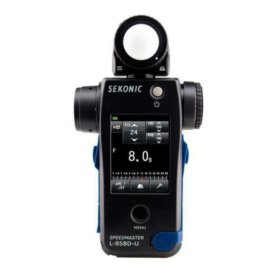
1. Names and Functions of Parts Names and Functions of Parts 1-1 Names of Parts Lumisphere Retracting Ring Front View Rear View Lumisphere Objective Lens Viewfinder Eyepiece (with diopter adjustment) Power Button Measuring Button Memory Button Touch Panel LCD Menu Button <<MENU>> USB Connector USB Connector Cover Synchro Terminal... -
Page 16: Functions Of Parts
1. Names and Functions of Parts 1-2 Functions of Parts The following table lists the functions of each part. Part Name Function Lumisphere Retracting Turn this to switch between the extended lumisphere and Ring retracted lumisphere. ( P35) Position the meter at subject with Lumisphere facing toward Lumisphere camera or light source during measurement. -
Page 17: Before Use
2. Before Use Before Use 2-1 Attaching the Strap Pass the strap (included) through the outer hole of the Strap Eyelet f. Pass the opposite end of the strap through the loop at the end of the strap. Strap Eyelet Strap WARNING Infants or toddlers may accidentally wrap the strap around their neck, so... -
Page 18: Inserting The Batteries
2. Before Use 2-2 Inserting the Batteries Prepare two AA batteries. Unlock the Battery Cover Latch e, and remove the Battery Cover d. Insert the batteries according to the "+" and "–" symbols in the Battery Compartment j. Align the tabs (three locations) of the Battery Cover to the holes of the meter. -
Page 19: Power On/Off
2. Before Use 2-3 Power ON/OFF Power ON Press the Power Button 5. The meter turns on. The Startup Screen appears on the LCD for Power Button one second. Then operating assignment for the Measuring Button (MEASURE) and Memory Button (MEMORY) are displayed on the Measuring Screen for two seconds. - Page 20 2. Before Use NOTICE ● The blue lettered "SEKONIC" Logo Screen is displayed after battery replacement and 24 hours after power OFF. ● The L-858D is executing a memory check while the blue progress bar is moving on the Logo Screen, so please do not turn OFF the power, as doing so may lead to damage.
-
Page 21: Auto Power Off Function
2. Before Use 2-4 Auto Power Off Function To save battery capacity, the meter will automatically turn off 5 minutes after the last button is pressed. NOTE ● All settings and measurements are saved in memory even Power Button after the meter has automatically turned off. When the power is turned ON, they will be displayed again. -
Page 22: Checking The Battery Capacity
This is an indication that the batteries have been depleted and they should be replaced immediately. It is recommended that spare batteries be kept on hand. ● When the meter is continuously used at room temperature, the battery should last 15 hours (based on Sekonic testing methods). 2-6 Replacing Batteries ●... -
Page 23: Screen Operations
3. Screen Operations Screen Operations 3-1 Basic Operations The screen, which is based on the touch panel system, allows you to select a target menu or item by touching the icon with your fingertip. ● The LCD backlight is lit when the meter is turned on. ●... - Page 24 3. Screen Operations Slide operations Setting Value Areas Slide a finger up or down on the setting value areas at any time to change setting values. Scroll Bar If a scroll bar is displayed on the screen, you can slide it to change the setting value. Touch and move the slider to change the setting Slider value on the scale.
- Page 25 3. Screen Operations Numeric Value Input Screen Numeric Value Input Screen The input value is displayed in this area. * The Filter Compensation Value Input Screen is used as an example. How to input a numeric value (Numeric Value Input Screen) Description 0-9, Decimal Inputs a numeric value.
- Page 26 3. Screen Operations Character Input Screen Upper Case Input Screen Lower Case Input Screen Numeric Value Input Screen How to input characters and numbers (Alphabet Input Screen and Number Input Screen) Description ■ The cursor indicates the location at which to input a value. ABC, abc, When touched, the input value is displayed at the top of the screen.
-
Page 27: Locking And Unlocking The Screen
3. Screen Operations 3-2 Locking and Unlocking the Screen You can lock the screen to prevent misoperation. When the screen is locked, touch operation is disabled. However, the Power Button , Measuring Button , and Memory Button still operational. The screen will stay locked even when power is turned OFF and ON. Measuring Screen Measuring Screen (For screen Measuring Screen... -
Page 28: Screen Transition
3. Screen Operations 3-3 Screen Transition The basic screen transition is as follows. A change in the Measuring Mode or settings can be made on the Measuring Screen. Power ON Measuring Mode Startup Screen * The modes displayed can be selected in Custom Setting. ( P170) Set the Measuring Mode that matches your intended use. -
Page 29: Screen Display
3. Screen Operations 3-4 Screen Display 3-4-1 Measuring Screen When the power is turned on, the Measuring Screen is displayed after the Startup Screen has been displayed for one second. Measuring Screen (Example in Radio Triggering Mode) * This example of the Measuring Screen shows all the items for explanation purposes. - Page 30 3. Screen Operations Part Name Description The percentage of flash light in the total exposure is displayed (in Flash Component steps of 10%) ( P73) Measured Value/ Displays information such as measured values and measuring units. Measuring Unit ( P20) Display Area Measured Value Displays the additional data for the measured value.
-
Page 31: Status Bar
3. Screen Operations Status bar This example shows all the items for explanation purposes. The displayed information vary depending on settings. Displayed item list Part Name Description Full battery power remaining. Battery Sufficient battery power remaining. Capacity Indicator Low battery power remaining. Have spare batteries ready. Display Replace the batteries immediately. -
Page 32: Measuring Operation/Display Area
3. Screen Operations 3-4-2 Measuring Operation/Display Area The measuring operation/display area consists of the following components: Measuring Mode Icon ● ● Setting Value Icon ● Measured value/measuring unit display area ● Analog scale Measuring Screen (Ambient T Priority Mode) Measuring Mode Icon Setting Value Icon (Ambient Mode) Measured Value/Measuring... - Page 33 3. Screen Operations Setting Value Icon You can set the shutter speed, aperture, etc. The setting value is displayed in the icon. The displayed icon varies depending on the Measuring Mode. Measuring Screen T (shutter speed) Priority F (Aperture) Priority Mode, Flash Measuring Mode Mode T+F (Shutter Speed/Aperture)
- Page 34 3. Screen Operations * If you touch the Setting Value Icon while the HD Cine Mode or Cine Mode is enabled, the display is enlarged. [Example] CINE Mode Measured value/measuring unit display area Displays information such as measured values and measuring units. Measuring Screen Unit of Measured Value: ISO (ISO...
- Page 35 3. Screen Operations Measuring Screen Unit of Measured Value: F (aperture) Flash Component ● Flash component: The ratio of flash light to the total exposure Measured Value/ Measuring Unit is displayed as a percentage Display Area (in steps of 10%) Measured Value Viewfinder Display NOTE...
- Page 36 3. Screen Operations Analog scale The analog scale displays the exposure setting for a current measurement and value relationships between two or more memorized measurements. Memory Pointer Memory Pointer Measured Value Pointer Measured value scale Depending on the Measuring Mode, the following values will be displayed on the scale.
-
Page 37: Usb Connection Screen
3. Screen Operations Flash analyzing scale The ambient light and flash light components are displayed on the analog scale when a flash light measurement is made. You can touch the scale to switch whether to display components or not. ( P73) Ambient Light (Orange) Component displayed No component displayed... -
Page 38: Viewfinder Display
3. Screen Operations 3-4-4 Viewfinder Display Viewfinder Display Viewfinder item list Part Name Description Measured value Displays the measured value. display Displays the flash component ratio and the Illuminance/luminance Additional display symbol. Exposure Displays only the plus or minus sign when exposure compensation compensation is set for the actually measured exposure value. - Page 39 3. Screen Operations Special Viewfinder display examples ● Shutter speeds higher that 1/1600s are abbreviated to the first digit and "k" multiplier symbol. Example: 1/2,000s = 2K Viewfinder Display Units: k (x 1,000) ● In T+F priority, ISO numbers higher than ISO 160,000 as the first 3 digits and k multiplier symbol.
-
Page 40: Tool Box Screen
3. Screen Operations 3-4-5 Tool Box Screen Touch the [Tool Box] Icon ( ) on the Measuring Screen to make the following settings. Set Average/Contrast Function Screen Measuring Screen Tool Box Screen Exposure To next page Compensation Select Incident/ Value Screen Spot Screen [Close] Button Set Exposure Profile... - Page 41 3. Screen Operations Memory Clear Screen Memory Recall Screen Tool Box Screen Page 2 Multi Clear Flash Duration Analysis t Value Screen Tool Box Screen Page 2 * The contents displayed on Number of Pre-flash Screen page 2 of the Tool Box Screen vary depending on the meter setting or whether optional accessories are attached.
- Page 42 3. Screen Operations Tool Box item list Part Name Description Set Average/Contrast Select ON or OFF. ( P118) Function Select Incident/Spot Select the light receiving method (Incident/Spot). ( P32) Set Exposure Input an Exposure compensation value. The allowable Compensation exposure compensation range is -9.9 EV to +9.9 EV. ( P125) Set filter compensation (you can input the filter compensation value or select the filter name).
-
Page 43: Menu Screen
3. Screen Operations 3-4-6 Menu Screen Touch the Menu Button to make the following settings. Custom Setting Menu Analog Scale Screen Screen Menu Button <<MENU>> Menu Screen Edit Exposure Profile Page 1 Edit Frame Rate Screen Screen [Close] Button Edit Shutter Angle Screen Edit Filter Screen Menu Screen... - Page 44 3. Screen Operations Menu item list Part Name Description Analog Scale Set the display of the analog scale. ( P22) Select a function or set and edit the displayed information. Custom Setting Menu ( P156) Edit exposure files created by Data Transfer Software on the Edit Exposure Profile meter side (about setting values and names).
-
Page 45: Basic Operations
4. Basic Operations Basic Operations 4-1 Basic Measurement Workflow Power ON ( P5) Incident light Extended lumisphere ( P35) Switch the light receiving Retracted lumisphere ( P35) ( P32) method ( P32) Reflected light • T (shutter speed) Priority Mode (... -
Page 46: Switch The Light Receiving Method
4. Basic Operations 4-2 Switch the Light Receiving Method 4-2-1 Incident Light System The incident light system measures the light that is falling on the subject using the Extended lumisphere or Retracted Lumisphere Function. Point the lumisphere at the camera lens (lens optical axis) from a location close to the subject, then make a measurement. - Page 47 4. Basic Operations NOTICE If you used Custom Functions to change the Function Measuring Screen Button assignment, sellect Incident/Spot using the Tool Box Screen. ( P34) NOTE Icon Description Displayed when the extended lumisphere is selected for incident light. Displayed when the retracted lumisphere is selected for incident light. Displayed when reflected light is selected.
-
Page 48: Setting On The Tool Box Screen
4. Basic Operations Setting on the Tool Box Screen Touch the [Tool Box] Icon ( ) on the Measuring Screen. The Tool Box Screen is displayed. Touch the [Select Incident/Spot] Button on the Tool Box Screen. The Select Incident/Spot Screen is displayed. Touch the [Incident Light] Radio Button. -
Page 49: Interchanging The Extended Lumisphere And Retracted Lumisphere
4. Basic Operations Interchanging the Extended Lumisphere and Retracted Lumisphere 1. Extending Lumisphere Extend the Lumisphere to measure the illumination of people, buildings, and other three dimensional subjects. Rotate the top of the Lumisphere Retracting Ring to securely align the mark on the ring with the lumisphere mark ( 2. - Page 50 4. Basic Operations NOTE Lumisphere If the Lumisphere is damaged or stains cannot be removed, Retracting Ring purchase a replacement of lumisphere for L-858 separately, and replace the defective lumisphere with the new one. 1) How to replace the Lumisphere Push down the Lumisphere Lock Lever .
-
Page 51: Reflected Light System
4. Basic Operations 4-2-2 Reflected Light System Switch the light receiving method to the reflected light system to make a measurement. The reflected light system measures the brightness (luminance) of the light reflected from the subject. It is useful to meter distant objects such as landscapes, if you cannot go to the location of the subject, or to meter subjects that generate light (neon signs, etc.), highly reflective surfaces, or... - Page 52 4. Basic Operations NOTICE If you used Custom Functions to change the Function Measuring Screen Button assignment, sellect Incident/Spot using the Tool Box Screen. ( P39) NOTE Icon Description Displayed when the extended lumisphere is selected for incident light. Displayed when the retracted lumisphere is selected for incident light. Displayed when reflected light is selected.
-
Page 53: Setting On The Tool Box Screen
4. Basic Operations Setting on the Tool Box Screen Touch the [Tool Box] Icon ( ) on the Measuring Screen. The Tool Box Screen is displayed. Touch the [Select Incident/Spot] Button on the Tool Box Screen. The Select Incident/Spot Screen is displayed. Touch the [Reflected Light (Spot)] Radio Button. -
Page 54: Measuring Area
4. Basic Operations Measuring Area The measuring area is the inside of circle in the Viewfinder Display viewfinder. The light receiving angle is 1 degree. Circle Diopter Scale Compensation While looking through the viewfinder, adjust the diopter by Viewfinder Eyepiece rotating the Viewfinder Eyepiece so that the circle and digital display can be seen clearly. -
Page 55: Setting The Measuring Button And Memory Button
4. Basic Operations 4-2-3 Setting the Measuring Button and Memory Button You can interchange the Measuring Button and Memory Button using Custom Setting. ( P168) Power Button 1. When mainly using the incident light system "Switching Measure / Memory Buttons" is set to "Standard"... - Page 56 4. Basic Operations NOTE Measuring Screen Each time the meter is powered on, the assignment of the Memory and Measurement Buttons will be displayed for two seconds. 3. When frequently using both the incident light and reflected light systems In the incident light system, the button position can be changed automatically to the standard configuration.
-
Page 57: Selecting The Measuring Mode
4. Basic Operations 4-3 Selecting the Measuring Mode Select the desired Measuring Mode. NOTICE If you change the Measuring Mode, the measured value is cleared. Touch the Measuring Mode Icon ( ) on the Measuring Screen to display the Measuring Mode Screen. - Page 58 4. Basic Operations Ambient Light CINE Mode Displays F-stop value for input frame rate, ISO sensitivity, and shutter angle values. ( P60) Ambient Light Illuminance lux Mode (Incident light measurement) Displays brightness value in lux (lx) unit. ( P69) Ambient Light Illuminance fc Mode (Incident light measurement) Displays brightness value in foot-candle (fc) unit.
- Page 59 4. Basic Operations Radio Triggering Multi (Cumulative) Flash Mode Detects and accumulate flash brightness after Measuring Button is pressed to send radio transmitted signal to radio receiver connected to flash. Displays F-stop value for input shutter speed and ISO sensitivity (When a transmitter sold separately is installed).
- Page 60 4. Basic Operations Operation * This section describes how to switch from the Ambient T Priority Mode to the Ambient CINE Mode. Touch the Measuring Mode Icon on the upper left of the screen. The Measuring Mode Screen is displayed. Measuring Screen Measuring Mode Screen Measuring...
-
Page 61: Measuring
5. Measuring Measuring 5-1 Measuring in Ambient Light Mode Continuous light like natural light (sunlight) as well as tungsten lamps and fluorescent lamps are measured in Ambient Light Mode. The following measuring methods are available in Ambient Light Mode. ● T (shutter speed) priority ●... -
Page 62: T (Shutter Speed) Priority Mode
5. Measuring 5-1-1 T (shutter speed) Priority Mode Displays aperture (F) for input ISO sensitivity and shutter speed values. Operation Touch the Measuring Mode Icon on the Measuring Screen. The Measuring Mode Screen is displayed. Touch the icon ( ) on the Measuring Mode Screen. When it is selected, the display changes to the Measuring Screen. - Page 63 5. Measuring Set the ISO sensitivity value on the [ISO] Icon. P197) Set the shutter speed on the [T] Icon. P197) Measuring Screen Setting Value Press the Measuring Button on the side of the meter to measure the light. The measured value (F-stop) will be displayed.
-
Page 64: F (F-Stop) Priority Mode
5. Measuring 5-1-2 F (F-stop) Priority Mode Displays shutter speed (T) for input ISO sensitivity and f-stop values. Operation Touch the Measuring Mode Icon on the Measuring Screen. The Measuring Mode Screen is displayed. Touch the icon ( ) on the Measuring Mode Screen. When it is selected, the display changes to the Measuring Screen. - Page 65 5. Measuring Set the ISO sensitivity value on the [ISO] Icon. P197) Set the aperture on the [F (f-stop)] Icon. P198) Measuring Screen Setting Value Press the Measuring Button on the side of the meter to measure the light. The measured value (shutter speed) will be displayed.
-
Page 66: T+F (Shutter Speed/F-Stop) Priority Mode
5. Measuring 5-1-3 T+F (Shutter Speed/F-stop) Priority Mode Displays ISO sensitivity for input shutter speed and f-stop values. The T+F (Shutter Speed/F-stop) Priority Mode is useful for today's digital cameras when a fixed speed and aperture are desired and the ISO can be adjusted for appropriate exposure. - Page 67 5. Measuring Set the shutter speed on the [T] Icon. P197) Set the aperture on the [F (f-stop)] Icon. P198) Measuring Screen Setting Value Press the Measuring Button to measure the light on the side of the meter. The measured ISO sensitivity value will be displayed.
-
Page 68: Hd Cine Mode
5. Measuring 5-1-4 HD CINE Mode Displays f-stop value for input shutter speed, ISO sensitivity and frame rate (f/s). Measuring Operation Touch the Measuring Mode Icon on the Measuring Screen. The Measuring Mode Screen is displayed. Touch the icon ( ) on the Measuring Mode Screen. - Page 69 5. Measuring Set the ISO sensitivity value on the [ISO] Icon. P197) Touch the [ISO] Icon to expand it. Slide the icon number up or down using your fingertip to set the measured value. The icon will return to its reduced size after the icon is not touched for a short time. Close-up Measuring Screen Set the frame rate on [f/s] Icon.
- Page 70 5. Measuring Press the Measuring Button on the side of the meter to measure the light. The measured value (F-stop) will be displayed. While the Measuring Button is being pressed, the meter measures continuously until the button is released. When the Measuring Button is released, the measurement is completed.
-
Page 71: Frame Rate Editing
5. Measuring Frame Rate Editing In addition to the standard frame rates available in the meter, up to 20 frame rates can be customized and displayed in the Meter Screen. The stored frame rates can be edited as desired. ( P198) Menu Screen, Page 1 Edit Frame Rate Edit Frame Rate Screen... - Page 72 5. Measuring Touch [Edit Frame Rate] Button to display the Edit Frame Rate Screen. Touch [Frame Rate] Button to display the Frame Rate Screen. Menu Screen Edit Frame Rate Frame Rate Screen Page 1 Screen [Frame Rate] Button Input a numeric value in the Input Frame Rate Screen. ...
- Page 73 5. Measuring Check the box of the desired frame rate. Touch the box ( ) to check it (check mark ). The checked frame rate is displayed after 1,000f/s on the Measured Screen. When the box is unchecked, it is deselected. Edit Frame Rate Screen The input numeric value is displayed.
-
Page 74: Cine Mode
5. Measuring 5-1-5 CINE Mode This mode measures the aperture for input frame rate (f/s), ISO sensitivity and shutter angle. Measuring Operation Touch the Measuring Mode Icon on the Measuring Screen. The Measuring Mode Screen is displayed. Touch the icon ( ) on the Measuring Mode Screen. - Page 75 5. Measuring Set the ISO sensitivity value on the [ISO] Icon. P197) Touch the [ISO] Icon to expand it. Slide the icon number up or down using your fingertip to set the measured value. The icon will return to its reduced size after the icon is not touched for a short time. Close-up Measuring Screen Set the shutter angle on the [Ang] Icon.
- Page 76 5. Measuring Press the Measuring Button on the side of the meter to measure the light. The measured value (F-stop) will be displayed. While the Measuring Button is being pressed, the meter measures continuously until the button is released. When the Measuring Button is released, the measurement is completed.
-
Page 77: Frame Rate Editing
5. Measuring Frame Rate Editing In addition to the standard frame rates available in the meter, up to 20 frame rates can be customized and displayed in the Meter Screen. The stored frame rates can be edited as desired. Menu Screen, Page 1 Edit Frame Rate Edit Frame Rate Screen Page 1... - Page 78 5. Measuring Touch [Edit Frame Rate] Button to display the Edit Frame Rate Screen. Touch [Frame Rate] Button to display the Frame Rate Screen. Menu Screen Edit Frame Rate Frame Rate Screen Page 1 Screen [Frame Rate] Button Input a numeric value in the Input Frame Rate Screen. P11) ...
- Page 79 5. Measuring Check the box of the desired frame rate. Touch the box ( ) to check it (check mark ). The checked frame rate is displayed after 1000f/s on the Measured Screen. When the box is unchecked, it is deselected. Edit Frame Rate Screen The input numeric value is displayed.
-
Page 80: Shutter Angle Editing
5. Measuring Shutter Angle Editing In addition to the standard shutter angles available in the meter, up to 20 shutter angles can be customized and displayed in the Meter Screen. The input shutter angle can be edited as desired. Menu Screen, Page 1 Edit Shutter Angle Edit Shutter Angle Screen Page 1... - Page 81 5. Measuring Touch the [Edit Shutter Angle] Button. The Edit Shutter Angle Screen is displayed. Touch the [Shutter Angle] Button. The Input Shutter Angle Screen is displayed. Menu Screen Edit Shutter Angle Screen Shutter Angle Screen Page 1 [Shutter Angle] Button Input a numeric value on the Input Shutter Angle Screen.
- Page 82 5. Measuring Check the box corresponding to the desired shutter angle. Touch the box ( ) to check it (check mark ). The checked shutter angle is displayed after Ang 358 on the Measuring Screen. When the box is unchecked, it is deselected. When checked (check mark ...
-
Page 83: Illuminance/Luminance Mode
5. Measuring 5-1-6 Illuminance/Luminance Mode Illuminance is measured using the Incident Light Mode, and luminance is measured using the Reflected Light (Spot) Mode. The following are the units that can be set. Select the Illuminance/Luminance Unit in the Custom Setting. ( P156) Lux (Unit: lx) Incident light measurement (... - Page 84 5. Measuring Switch to the retracted lumisphere. If extended lumisphere is selected, rotate the Lumisphere Retracting Ring to switch to the retracted lumisphere ( ) position. Measuring Screen Lumisphere Retracting Ring Retracted Mark ( Point the light receptor directly toward the light source. Press the Measuring Button on the side of the meter to measure the light.
-
Page 85: Luminance Measuring
5. Measuring Luminance Measuring Operation Switch the light receiving method to reflected light. P37) Touch the Measuring Mode Icon on the Measuring Screen. The Measuring Mode Screen is displayed. Touch the icon ( ) on the Measuring Mode Screen. When it is selected, the display changes to the Measuring Screen. - Page 86 5. Measuring While looking through the viewfinder, press the Measuring Button on the side of the meter to measure the light. While looking through the viewfinder, locate the subject area to be measured within the finder circle. Press the Measuring Button , and the luminance will be displayed in Candelas square meter (measured value).
-
Page 87: Measuring In Flash Light Mode
5. Measuring 5-2 Measuring in Flash Light Mode Flash illumination is light that is produced by the very brief light pulse of an electronic flash unit or flash bulb. Flash measurement is available in the following modes: ● Cordless Flash Mode ●... -
Page 88: Cordless Flash Mode
5. Measuring NOTE ● Shutter speed and f-stop (aperture) values can be displayed in 1, 1/2 and 1/3 stop increments in Custom Setting. ( P163) ● After taking a measurement, changing a setting value (ISO value or shutter speed) will display the corresponding aperture. - Page 89 5. Measuring Set the light receiving method. Switch to the Incident light, extended lumisphere ( )/retracted lumisphere ( ), or reflected light. ( P32, P37) Set the ISO sensitivity value on the [ISO] Icon. P197) Set the shutter speed on the [T] Icon. P197) ...
- Page 90 5. Measuring Trigger the flash unit manually while the Measuring Mode Icon ) is blinking. When the flash light is detected, the measurement is made automatically and the measured value (F-stop) is displayed. Measuring Screen Flash Component Measured Value (F-stop) NOTICE In case of the following, please follow "5-2-3 Cord Flash Mode".
-
Page 91: Number Of Pre-Flash
5. Measuring Number of Pre-flash For red-eye prevention and auto-flash light adjustment, some devices can pre-flash before main flash burst. With the normal setting, the light meter will measure the pre-flash bursts and not the main flash burst. To take a successful reading, activate the pre-flash feature in the Tool Box. Operation Touch the [Tool Box] Icon ( ) on the Measuring Screen. - Page 92 5. Measuring Touch the radio button of the Number of Pre-flash Button. Set the number of pre-flash on the Number of Pre-flash Screen. The display returns to the Measuring Screen. If you do not change this number, touch the [Close] Button to return to the Measuring Screen.
-
Page 93: Cordless Multi (Cumulative) Flash Mode
5. Measuring 5-2-2 Cordless Multi (Cumulative) Flash Mode This Measuring Mode is used when the light generated by the flash at one time is inadequate for the desired F-stop setting. Repeated flash pops can be accumulated until the desired F-stop value is displayed. When the Measuring Button is pressed, the light meter is set to the Standby Mode (90 seconds) and makes a measurement by activating the flash. - Page 94 5. Measuring Set the ISO sensitivity value on the [ISO] Icon. P197) Set the shutter speed on the [T] Icon. P197) Measuring Screen Setting Value NOTICE Make sure that the settings are within the specifications of the camera and flash system.
- Page 95 5. Measuring Trigger the flash unit manually while the Measuring Mode Icon ) is blinking. When the flash light is detected, the measurement is made automatically and the measured value (F-stop) is displayed. Repeat triggering the flash unit until the desired F-stop is displayed during the Standby Mode.
-
Page 96: Multi Clear
5. Measuring Multi Clear Clears the cumulative count. Operation Touch the [Tool Box] Icon ( ) on the Measuring Screen. The Tool Box Screen is displayed. Touch the [Next Page] Icon ( ) of the Tool Box to display the Tool Box showing "Multi Clear". -
Page 97: Number Of Pre-Flash
5. Measuring NOTE When the standby state is released and when the Measuring Button is pressed again, the measuring will start with a cumulative count of "0". Number of Pre-flash For red-eye prevention and auto-flash light adjustment, some devices can pre-flash before main flash burst. - Page 98 5. Measuring Touch the radio button of the Number of Pre-flash Button. Set the number of pre-flash on the Number of Pre-flash Screen. The display returns to the Measuring Screen. If you do not change this number, touch the [Close] Button to return to the Measuring Screen.
-
Page 99: Cord Flash Mode
5. Measuring 5-2-3 Cord Flash Mode In this Measuring Mode, a synchro cord (sold separately) is used to connect the flash to the meter. Use this Cord Flash Mode when you need to ensure synchronization with the flash or use a flash bulb. After pressing the Measuring Button , the meter trigger the flash unit and displays F-stop value. - Page 100 5. Measuring Set the ISO sensitivity value on the [ISO] Icon. P197) Set the shutter speed on the [T] Icon. P197) Measuring Screen Setting Value NOTICE Make sure that the settings are within the specifications of the camera and flash system.
-
Page 101: Cord Multi (Cumulative) Flash Mode
5. Measuring 5-2-4 Cord Multi (Cumulative) Flash Mode This Measuring Mode is used when the light generated by the flash at one time is inadequate for the desired F-stop setting. Repeated flash pops can be accumulated until the desired F-stop value is displayed. The measured value (F-stop) is displayed for each trigger of the flash. - Page 102 5. Measuring Set the ISO sensitivity value on the [ISO] Icon. P197) Set the shutter speed on the [T] Icon. P197) Measuring Screen Setting Value NOTICE Make sure that the settings are within the specifications of the camera and flash system.
-
Page 103: Multi Clear
5. Measuring Multi Clear Clears the cumulative count. Operation Touch the [Tool Box] Icon ( ) on the Measuring Screen. The Tool Box Screen is displayed. Touch the [Next Page] Icon ( ) of the Tool Box to display the Tool Box showing "Multi Clear". -
Page 104: Radio Triggering Flash Mode
5. Measuring 5-2-5 Radio Triggering Flash Mode (Available when a transmitter sold separately is installed) The meter detects flash brightness after Measuring Button is pressed to send radio transmitted signal to radio receiver connected to flash. Displays F-stop value for input ISO sensitivity and shutter speed. -
Page 105: Hss (High Speed Synchro) Flash Cordless Mode
5. Measuring 5-3 HSS (High Speed Synchro) Flash Cordless Mode Measures the HSS (High Speed Synchro) or FP flash. NOTICE The HSS flash can be measured in Cordless Mode only. 5-3-1 HSS (High Speed Synchro) Flash Cordless Mode Select this mode to measure the brightness of a flash activated in HSS (High Speed Synchro) Mode. - Page 106 5. Measuring Set the light receiving method. Switch to the Incident light, extended lumisphere ( )/retracted lumisphere ( ), or reflected light. ( P32, P37) Set the ISO sensitivity value on the [ISO] Icon. P197) Set the shutter speed on the [T] Icon. P197) ...
-
Page 107: Number Of Pre-Flash
5. Measuring When the Measuring Mode Icon ( ) is blinking, release the shutter button of the camera that is set to HSS Flash Mode to fire the flash unit. When the flash light is detected, the measurement is made automatically and the measured value (F-stop) is displayed. - Page 108 5. Measuring Touch the [Next Page] Icon ( ) of the Tool Box to display the Tool Box showing "Number of Pre-flash". This button is enabled if Flash Mode is selected. If it is grayed out, check the Measuring Mode. ( P44) Touch the [Number of Pre-flash] Button of the Tool Box.
-
Page 109: Measuring In Flash Duration Analysis Mode
5. Measuring 5-4 Measuring in Flash Duration Analysis Mode In the Flash Duration Analysis Mode, F-stop, flash duration time and graph of flash waveform can be measured for input shutter speed and ISO sensitivity. Flash Duration Analysis is performed with incident light Measuring Mode only. Flash duration measurement is available in the following modes: ●... - Page 110 5. Measuring Set the light receiving method. Incident light system Switch to the extended lumisphere ( )/retracted lumisphere ). ( P32) Set the ISO sensitivity value on the [ISO] Icon. P197) Set the shutter speed on the [T] Icon. P197) ...
- Page 111 5. Measuring Trigger the flash unit manually while the Measuring Mode Icon ( is blinking. When the flash light is detected, the measurement is made automatically and the measured value (F-stop) will be displayed. Measuring Screen Flash Component Flash Duration Time Measured Value (F-stop) NOTICE...
-
Page 112: Number Of Pre-Flash
5. Measuring NOTE ● When the measured value display area is touched, both flash waveform graph and measured value are displayed. When it is touched again, the display returns to the previous screen. Flash Duration Analysis Cordless Mode Flash Waveform Graph Screen Measuring Screen Touching the Measured value... - Page 113 5. Measuring Touch the [Number of Pre-flash] Button of the Tool Box. The Number of Pre-flash Screen is displayed. If you do not change this number, touch the [Close] Button. Measuring Screen Tool Box Screen Tool Box Screen Page 1 Page 2 To next page [Close] Button...
-
Page 114: Flash Duration Analysis T Value
5. Measuring Flash Duration Analysis t Value The t value can be set in steps of 0.1 at a range of 0.1 to 0.9. The flash duration time varies depending on the input t value. Operation Touch the [Tool Box] Icon ( ) on the Measuring Screen. - Page 115 5. Measuring Input the "Reference" of 0.1 to 0.9 by touching the numeric value. The t value can be set in steps of 0.1 at a range of 0.1 to 0.9. The first "0." is fixed. Input the first digit decimal only. (To set "0.1", input "1".) Flash Duration Analysis Flash Duration Analysis t Value Screen...
-
Page 116: Flash Duration Analysis Code Mode
5. Measuring 5-4-2 Flash Duration Analysis Code Mode Press the Measuring Button with a meter-flash connection. When the flash brightness is detected, F-stop, flash duration time and graph of flash waveform are measured for input shutter speed and ISO sensitivity. Measuring Operation Synchro Cord (sold separately) - Page 117 5. Measuring Set the ISO sensitivity value on the [ISO] Icon. P197) Set the shutter speed on the [T] Icon. P197) Measuring Screen Setting Value NOTICE Measuring ● Make sure that the settings are within the specifications Screen of the camera and flash system.
- Page 118 5. Measuring NOTICE ● The flash duration time and graph are displayed in the Flash Duration Analysis Mode, however, they cannot be stored in the memory. They are cleared if the Measuring Mode is changed or the POWER switch is turned OFF.
-
Page 119: Flash Duration Analysis T Value
5. Measuring Flash Duration Analysis t Value The t value can be set in steps of 0.1 at a range of 0.1 to 0.9. The flash duration time varies depending on the input t value. Operation Touch the [Tool Box] Icon ( ) on the Measuring Screen. - Page 120 5. Measuring Input the "Reference" of 0.1 to 0.9 by touching the numeric value. The t value can be set in steps of 0.1 at a range of 0.1 to 0.9. The first "0." is fixed. Input the first digit decimal only. (To set "0.1", input "1".) Flash Duration Analysis Flash Duration Analysis t Value Screen...
-
Page 121: Flash Duration Analysis Radio Triggering Mode
5. Measuring 5-4-3 Flash Duration Analysis Radio Triggering Mode (Available when a transmitter sold separately is installed) The meter detects flash brightness after Measuring Button is pressed to send radio transmitted signal to radio receiver connected to flash. F-stop, flash duration time and graph of flash waveform are displayed for input ISO sensitivity and shutter speed. -
Page 122: Out Of Displayed Range Or Measuring Range
5. Measuring 5-5 Out of Displayed Range or Measuring Range (* This example explains what needs to be done in Cord Flash Mode.) 5-5-1 When Displayed Range Is Exceeded For any given shutter speed and ISO setting, "Under" or "Over" is displayed if the measured value (F-stop) exceeds the display range even if it is within measuring range. -
Page 123: When Measuring Range Is Exceeded
5. Measuring 5-5-2 When Measuring Range Is Exceeded When the amount of light is outside the measuring range of the meter, "Over" and "Under" will appear and blink. When this occurs, adjust the brightness level to obtain a measurement. When brightness is under the When brightness is over the measuring range measuring range... -
Page 124: Functions
6. Functions Functions 6-1 Memory Function This meter can save measured values in the memory. This function is available in the following Measuring Modes. Ambient Mode ● T Priority Mode ● F Priority Mode ● TF Priority Mode HD Cine Mode ●... -
Page 125: How To Save Values In The Memory
6. Functions 6-1-1 How to Save Values in the Memory Operation Press the Measuring Button 6. The measured value at that time will be displayed. In Ambient Mode, while the Measuring Button is held down, the meter continues to make measurements. When the Measuring Button is released, the measurement ends. - Page 126 6. Functions NOTICE The Memory Function cannot be used in the following Measuring Modes. ● Cord Multi (Cumulative) Flash Mode ● Cordless Multiple (Cumulative) Flash Mode ● Illuminance/Luminance Measuring Mode ● Flash Duration Analysis Mode NOTE Memory count warning Measuring Screen Up to nine measured values can be saved in the memory.
-
Page 127: Memory Clear
6. Functions 6-1-2 Memory Clear This function individually or collectively clears measured values that are saved in the memory. The Memory Clear Screen displays memory information (memory count, incident light ( ) or reflected light ( ), and measured value) in the order in which they are saved in the memory. -
Page 128: Individual Clear
6. Functions Individual Clear Operation Select the memory value to be deleted on the Memory Clear Screen. Multiple memory values are selectable. Touch [Clear] Button. This changes the display to the Selected Memory Clear Confirmation Screen, and the "Selected memory is cleared. Are you sure?" message is displayed. When you touch [Close] Button, the display returns to the Measuring Screen without clearing the memory value. -
Page 129: Collective Clear
6. Functions Collective Clear The measured values that are saved in the memory can be cleared collectively. Operation Touch [ALL] Button on the Memory Clear Screen. This changes the display to the All Clear Confirmation Screen, and the "All memory is cleared. Are you sure?" message is displayed. Touch [OK] Button. -
Page 130: Memory Recall
6. Functions 6-1-3 Memory Recall This function recalls the measured values that are saved in the memory to enable the user to view details. This screen displays memory information (memory count, incident light ( ) or reflected light ( ), and measured value) in the order in which they are saved in the memory. - Page 131 6. Functions Touch the item to be recalled. Contents saved in the memory are displayed on the Measuring Screen. (Green background) Memory Recall Screen Recall Screen Currently Recalled Memory [Close] Button [Memory Recall] Button NOTE ● In Ambient Mode, the measured values saved in the memory are maintained even if the mode is switched.
-
Page 132: Average/Contrast Function
6. Functions Touch [Memory Recall] Button. If you touch [Memory Recall] Button on the Recall Screen to display another memory value, the display returns to the Memory Recall Screen. If you touch [Close] Button, the display returns to the Measuring Screen instead of returning to the Memory Recall Screen. - Page 133 6. Functions Operation Measuring Button Press the Measuring Button 6. Press this button to make a measurement. Press the Memory Button 7. The measured value is saved in the memory. Each measured value that is saved in the memory is displayed Memory as a dot ( ) on the analog scale.
- Page 134 6. Functions NOTE The Set Average/Contrast Function Icon is set to Function Button -1 Button in Factory Setting. When the Set Average/Contrast Function Icon is not displayed, set the Function Button in Custom Setting ( P160), or set the Set Average/ Contrast Function on the Tool Box Screen (...
-
Page 135: Contrast Function
6. Functions Contrast Function This function is useful for checking studio lighting or illumination unevenness. This function is also convenient when you check the difference in luminance between the intermediate value and the highlight and/or shadow value for landscape shooting. While you are holding down the Measuring Button at the comparison position after defining the measured value at a specific point as the standard value, a difference... - Page 136 6. Functions Touch the Set Average/Contrast Function Icon ( The "Ave" symbol appears on the screen. When the Contrast Function is active, the Set Average/Contrast Function Icon ( ) is highlighted ( The measured value of the main light source is saved in the memory as the standard value.
- Page 137 6. Functions Measuring Screen Measuring Screen Enlarge Analog Scale Measured Reference Value Value " EV" Symbol The Average Function is active. Set Average/Contrast Function Icon Reflected-light measurement example Viewfinder Display EV Difference of Measured Value Illumination Ratio 16:1 NOTE ● To determine the final exposure in the incident light system, turn on the main and sub light sources, and set the right receptor to the extended lumisphere.
-
Page 138: Average/Contrast Function Setting On The Tool Box Screen
6. Functions Average/Contrast Function Setting on the Tool Box Screen Operation Touch the [Tool Box] Icon ( ) on the Measuring Screen. The Tool Box Screen is displayed. Touch the [Set Average/Contrast Function] Button on the Tool Box Screen. The Set Average/Contrast Function Screen is displayed. Touch the "ON"... -
Page 139: Exposure Compensation Function
6. Functions 6-3 Exposure Compensation Function This function is useful when compensation is necessary for highlight and/or shadow in reflected-light measurements. The input value range is -9.9 EV to +9.9 EV in 0.1 step increments. To use the Set Exposure Compensation Function, first specify the Measuring Mode (incident light system or reflected light system). - Page 140 6. Functions Operation Touch the [Tool Box] Icon ( ) on the Measuring Screen. The Tool Box Screen is displayed. Touch the [Set Exposure Compensation] Button on the Tool Box Screen. The Exposure Comp. Value Screen is displayed. Set the compensation value. Set the compensation value on the Exposure Comp.
-
Page 141: Filter Compensation Function
6. Functions 6-4 Filter Compensation Function This function registers a filter compensation value in the light meter. Setting this value enables you to obtain the measurement result to which the filter compensation value is applied. If the filter is used in front of camera lens, the light coming into the camera is decreased, so this "decreased"... -
Page 142: Input Filter Comp. Value
6. Functions 6-4-1 Input Filter Comp. Value Directly enter a filter compensation value using a numeric value. The input value range is +/-12 EV in 0.1 EV step increments. Operation Touch the [Tool Box] Icon ( ) on the Measuring Screen. The Tool Box Screen is displayed. - Page 143 6. Functions Input the compensation value on the Filter Comp. Value Screen. (See P11 for details about how to input the value.) Touch [OK] Button. The value is applied, and the display returns to the Filter Compensation Screen. Then, the entered filter compensation value is displayed. To return to the Filter Compensation Screen without changing the value, touch [Cancel] Button.
-
Page 144: Selecting A Filter
6. Functions 6-4-2 Selecting a Filter You can select up to four pre-registered filter name ( P199). Operation Touch the [Tool Box] Icon ( ) on the Measuring Screen. The Tool Box Screen is displayed. Touch the [Set Filter Compensation] Button on the Tool Box Screen. - Page 145 6. Functions Touch any of four [Filter Name] Buttons on the Filter Pack in Use Screen. The Select User Filter Screen is displayed. When there are multiple pages, press the [Next Page] Icon ( ) to display different pages. ( P199) Touch the radio button on the Filter Pack in Use Screen to select the desired filter.
- Page 146 6. Functions Check that the selected filter name is displayed. Check that the selected filter name is registered. Touch [OK] Button on the Filter Compensation Screen. The value is applied, and the display returns to the Measuring Screen. Then, the Filter Compensation Icon ( ) and the compensation value are displayed on the status bar.
-
Page 147: User-Defined Filter Compensation Settings
6. Functions 6-4-3 User-defined Filter Compensation Settings You can register up to 30 user-defined filter compensation values in addition to the standard filter compensation values. The registered filter compensation values can be edited freely. Menu Screen Edit Filter Edit Filter Page 1 Page 1 Page 2... - Page 148 6. Functions Operation Press the Menu Button on the meter. The Menu Screen is displayed. Touch the [Edit Filter] Button. The Edit Filter Screen is displayed. Menu Button Touch [Filter Name] Button of the desired filter. The Edit Filter Screen is displayed. Menu Screen Edit Filter Screen Edit Filter Screen...
- Page 149 6. Functions Input the filter name. P12) You can input the filter name using up to 31 characters. Touch [OK] Button. The display returns to the Edit Filter Screen. To return to the Edit Filter Screen without changing the name, touch the [Cancel] Button. Filter Name Screen Displays the alphanumeric...
- Page 150 6. Functions Input the filter compensation value. P11) The input value range is +/-12 EV in 0.1 EV step increments. Touch [OK] Button. The display returns to the Edit Filter Screen. To return to the Edit Filter Screen without changing the value, touch [Cancel] Button. Filter Comp.
- Page 151 6. Functions Touch the check box of the filter name. Touch the box ( ) to check (check mark ) to display the filter name in the Select User Filter Screen on the Tool Box. ( P130) When the box is unchecked, it is not listed.
-
Page 152: Deselecting A Filter
6. Functions 6-4-4 Deselecting a Filter If "No Filter" is selected, any filter compensation is not applied to the measured value. Operation Touch the [Tool Box] Icon ( ) on the Measuring Screen. The Tool Box Screen is displayed. Touch the [Set Filter Compensation] Button on the Tool Box Screen. The Filter Compensation Screen is displayed. -
Page 153: Mid. Tone Function
6. Functions 6-5 Mid. Tone Function This function is used to specify a measured value as the standard of light measurements and put it at the center of EV scale. The Mid. Tone Function has four modes: Setting name Description Set from Current Specify the measured value as the Mid. -
Page 154: Set From Memory
6. Functions Touch the [Tool Box] Icon ( ) on the Measuring Screen. The Tool Box Screen is displayed. Touch the [Set Mid. Tone] Button on the Tool Box Screen. The Set Mid. Tone Screen is displayed. Touch the [Set from Current Measurement] Button on the Set Mid. Tone Screen. - Page 155 6. Functions Operation Touch the [Tool Box] Icon ( ) on the Measuring Screen. The Tool Box Screen is displayed. Touch the [Set Mid. Tone] Button on the Tool Box Screen. The Set Mid. Tone Screen is displayed. Touch the [Set from Memory] Button on the Set Mid. Tone Screen. This displays the Mid.
-
Page 156: Modify Current Mid. Tone
6. Functions Modify Current Mid. Tone Fine-tune the currently set Mid. Tone value. Operation Touch the [Tool Box] Icon ( ) on the Measuring Screen. The Tool Box Screen is displayed. Touch the [Set Mid. Tone] Button on the Tool Box Screen. The Set Mid. - Page 157 6. Functions Touch the arrow icon ( ) or slide the number on the Modify Current Mid. Tone Screen. Select the desired Mid. Tone value. Touch [OK] Button. The change is applied and the displays to the Measuring Screen. To return to the Measuring Screen without changing the value, touch [Cancel] Button. The newly set Mid.
-
Page 158: Mid. Tone Recall
6. Functions 6-5-2 Mid. Tone Recall This function recalls the set Mid. Tone value to view details. Operation Touch the [Tool Box] Icon ( ) on the Measuring Screen on which the Mid. Tone value is specified. The Tool Box Screen is displayed. Touch the [Mid. -
Page 159: Mid. Tone Clear
6. Functions 6-5-3 Mid. Tone Clear This function clears the set Mid. Tone value. Operation Touch the [Tool Box] Icon ( ) on the Measuring Screen on which the Mid. Tone value is set. The Tool Box Screen is displayed. Touch the [Mid. -
Page 160: Exposure Profile Function
Exposure Profile Target II Exposure Profile Target -7.0 -6.0 -5.0 -4.0 -3.0 -2.0 -1.0 +1.0 +2.0 +3.0 +4.0 +5.0 Deviation from intermediate concentration (ΔEV) For details, refer to the Software Guide of Data Transfer Software. (downloadable from the website, www.sekonic.com) -
Page 161: Set Exposure Profile
6. Functions 6-6-2 Set Exposure Profile Operation Touch the [Tool Box] Icon ( ) on the Measuring Screen. The Tool Box Screen is displayed. Touch the [Set Exposure Profile] Button on the Tool Box Screen. The Set Exposure Profile Screen is displayed. Measuring Screen Tool Box Screen Page 1... -
Page 162: Edit Exposure Profile
6. Functions 6-6-3 Edit Exposure Profile You can specify whether to display or not in the list on the "Set Exposure Profile" Screen of the Tool Box Screen. You can also edit exposure profiles created using Data Transfer Software on the meter side (about setting values and names) or create exposure profiles manually using this meter only. -
Page 163: Display Or Not On The Set Exposure Profile Screen (Tool Box)
6. Functions Display or not on the Set Exposure Profile Screen (Tool Box) Operation Press the Menu Button on the meter. The Menu Screen is displayed. Touch the [Edit Exposure Profile] Button. The Edit Exposure Profile Screen is displayed. Menu Button Menu Screen, Page 1 Touch the check box of the exposure profile name. - Page 164 6. Functions Touch [Close] Button. The display returns to the Menu Screen. Menu Screen [Close] Button Touch [Close] Button on the Menu Screen. The display returns to the Measuring Screen.
-
Page 165: Edit Exposure Profile
6. Functions Edit Exposure Profile Although you can create an exposure profile using Data Transfer Software and transfer it to the meter, you can edit the stored exposure profil or directly enter an exposure profile into the meter manually. Operation Touch the [Edit Exposure Profile] Button. - Page 166 6. Functions Touch the [Exposure Profile Name] Button on the Edit Exposure Profile Screen. The Exposure Profile Name Screen is displayed. Input the name. Input the name on the Exposure Profile Name Screen. ( P12) Edit Exposure Profile Screen Exposure Profile Name Screen Input the name here.
- Page 167 6. Functions Touch the icon for the desired light receiving method and light source in "Edit Exposure Profile Data" on the Edit Exposure Profile Screen. The ISO Sensitivity of Edit Exposure Profile Data Screen is displayed. Edit Exposure Profile Screen [Light Receiving Method / Light Source] Icon [Close] Button...
- Page 168 6. Functions Edit the camera sensitivity characteristics. Set Camera Sensitivity Characteristic Screen Compensation Value Cursor Compensation Value (Synchronized with the cursor) Clipping Point (-) Clipping Point (+) Dynamic Range (-) Dynamic Range (+) [OK] Button [Cancel] Button [Default] Button 1 Compensation value cursor The compensation value can be set between -5 EV and +5 EV in 0.1 EV step increments.
- Page 169 6. Functions Touch [Close] Button on the ISO sensitivity selection on Edit Exposure Profile Data Screen. The display returns to the Edit Exposure Profile Screen. Repeat Steps 6 to 9. Edit another light receiving method and light source as needed. Edit Screen Edit Exposure Profile Screen [Light...
-
Page 170: Custom Setting
6. Functions 6-7 Custom Setting The meter can be customized to desired measuring and display preferences. Menu Screen, Page 1 [Custom Setting] Button Custom Setting Menu Custom Setting Menu Custom Setting Menu Page 1 Page 2 Page 3 To previous page To next page [Close] Button "Radio System Preference"... -
Page 171: Custom Setting List
6. Functions 6-7-1 Custom Setting List Setting Custom Default Item Setting Name Setting Average/ Average/ Exposure Filter Function Contrast Incident/Spot Mid. Tone Contrast Compensation Compensation Button -1 Function Selection ON/OFF Function ON/OFF ON/OFF ON/OFF ON/OFF Average/ Exposure Filter Function Contrast Incident/Spot Mid. - Page 172 6. Functions Setting Custom Default Item Setting Name Setting HSS Flash Mode Flash Duration Analysis Mode Cordless Mode b) Cord Mode Radio Triggering *4, *7 Mode Illuminance / Additional Data None None Luminance Illuminance / Foot-candle Luminance Lux or cd/m Unit Foot-lambert Color Theme...
-
Page 173: Custom Setting Procedure
6. Functions 6-7-2 Custom Setting Procedure Operation Press the Menu Button on the meter. The Menu Screen is displayed. Touch the [Custom Setting] Button. The Custom Setting Menu Screen is displayed. Menu Button Menu Screen, Page 1 [Custom Setting] Button Custom Setting Menu Custom Setting Menu Custom Setting Menu... -
Page 174: Function Button -1 Setting
6. Functions Select the page to display the desired item to set. Touch the [Next Page] / [Previous Page] Icon ( ) to display the target page. Touch the desired item name. The Item Setting Screen is displayed. Touch the radio button to select the desired item. - Page 175 6. Functions Operation Touch the [Function Button -1] Button on page 1 of the Custom Setting Menu Screen. The Function Button -1 Screen is displayed. Touch the desired item. Touch the desired radio button or an area around the item name to select. Touch [Close] Button.
-
Page 176: Function Button -2 Setting
6. Functions Function Button -2 Setting Assign the Function Button -2 on the Measuring Screen. Items are common to Function Button -1. Measuring Screen Function Button -2 Operation Touch the [Function Button -2] Button on page 1 of the Custom Setting Menu Screen. -
Page 177: Increments Of T+F" Setting
6. Functions Touch [Close] Button on the Custom Setting Menu Screen. The display returns to the Menu Screen. Touch [Close] Button on the Menu Screen. The display returns to the Measuring Screen. The selected item (Filter Compensation ON/OFF) has been set to Function Button -2 on the Measuring Screen. - Page 178 6. Functions Touch the desired item. Touch the desired radio button or an area around the item name to select. Touch [Close] Button. The display returns to the Custom Setting Menu Screen. Custom Setting Menu Screen Increments of T+F Screen Default [Close] Button...
-
Page 179: Display Of 1/10 Step Increments" Setting
6. Functions "Display of 1/10 Step Increments" Setting Set the display of 1/10 step increments of the measured value. Measuring Screen Measuring Screen Display of 1/3 step with 1/10 increments ON Display of 1/3 step with 1/10 increments OFF Display of 1/10 Step Increments Viewfinder Display... -
Page 180: Compensation +/- Preference
6. Functions Touch [Close] Button on the Custom Setting Menu Screen. The display returns to the Menu Screen. Touch [Close] Button on the Menu Screen. The display returns to the Measuring Screen, and the updated content is applied to the Measuring Screen. Custom Setting Menu Screen Menu Screen [Close]... - Page 181 6. Functions Touch [Close] Button. The display returns to the Custom Setting Menu Screen. Custom Setting Menu Screen Compensation +/- Preference Screen Default [Close] Button Touch [Close] Button on the Custom Setting Menu Screen. The display returns to the Menu Screen. Touch [Close] Button on the Menu Screen.
-
Page 182: And Memory Button 7
6. Functions Setting for Switching the Measuring Button and Memory Button To improve the operability, you can interchange the button functions between the incident light system and reflected light system. NOTE ● Standard: Used for measurement in the incident light system. Measuring Screen Memory Measuring... - Page 183 6. Functions Operation Touch the [Switching Measure / Memory Buttons] Button on page 1 of the Custom Setting Menu Screen. The Switching Measure / Memory Buttons Screen is displayed. Touch the desired item. Touch the desired radio button or an area around the item name to select. Touch [Close] Button.
-
Page 184: Ambient Mode Setting
6. Functions Ambient Mode Setting You can select Measuring Modes to be displayed on the Measuring Mode Screen. Display of all of Ambient Modes can be switched ON or OFF collectively, or Measuring Mode can be switched ON/OFF individually. Measuring Mode Screen Measuring Mode Screen Measuring Mode Screen Default (All ON) - Page 185 6. Functions Touch the check boxes of the Measuring Modes to display or not. To display, select their check boxes ( ). To hide, clear the check boxes ( ). If you clear the "Ambient Mode" check box, all the Ambient Modes are hidden collectively, and you will not be able to select any Measuring Mode under "Ambient Mode".
-
Page 186: Flash Mode Setting
6. Functions Flash Mode Setting You can select Measuring Modes to be displayed on the Measuring Mode Screen. Display of all Flash Modes can be switched ON or OFF collectively, or Measuring Mode can be switched ON/OFF individually. Measuring Mode Screen Measuring Mode Screen Measuring Mode Screen Default (All ON) - Page 187 6. Functions Touch the check boxes of the Measuring Modes to display or not. To display, select their check boxes ( ). To hide, clear the check boxes ( ). If you clear the "Flash Mode" check box, all the Flash Modes are hidden collectively, and you will not be able to select any Measuring Mode under "Flash Mode".
-
Page 188: Hss Flash Mode Setting
6. Functions HSS Flash Mode Setting You can select Measuring Modes to be displayed on the Measuring Mode Screen. Set the HSS (High Speed Synchro) Mode to ON or OFF. Measuring Mode Screen Measuring Mode Screen Default (All ON) HSS Flash Mode OFF Operation Touch the [HSS Flash Mode] Button on page 2 of the Custom Setting Menu Screen. - Page 189 6. Functions Check the HSS Flash Mode check box. To display, select their check boxes ( ). To hide, clear the check boxes ( ). The HSS Flash Mode is only available in the Cordless Mode. Therefore, all modes are displayed or hidden regardless of whether "HSS Flash Mode"...
-
Page 190: Flash Duration Analysis Mode Setting
6. Functions Flash Duration Analysis Mode Setting You can select Measuring Modes to be displayed on the Measuring Mode Screen. Display of all Flash Duration Analysis Modes can be switched ON or OFF collectively, or Measuring Mode can be switched ON/OFF individually. Measuring Mode Screen Measuring Mode Screen Measuring Mode Screen... - Page 191 6. Functions Touch the check boxes of the Measuring Modes you want to display or hide. To display, select their check boxes ( ). To hide, clear the check boxes ( ). If you clear the "Flash Duration Analysis Mode" check box, all the Flash Duration Analysis Modes are hidden collectively, and you will not be able to select any Measuring Mode under "Flash Duration Analysis Mode".
-
Page 192: Additional Data Setting
6. Functions Additional Data Setting Set the contents of additional data to be displayed on the lower right of the measurement value on the Measuring Screen. Measuring Screen Measuring Screen Measuring Screen Default Additional data for Additional data for (No additional data) EV value illuminance / luminance Operation... - Page 193 6. Functions Touch [Close] Button on the Custom Setting Menu Screen. The display returns to the Menu Screen. Touch [Close] Button on the Menu Screen. The display returns to the Measuring Screen, and the updated content is applied to the Measuring Screen. Custom Setting Menu Screen Menu Screen [Close]...
-
Page 194: Color Theme Setting
6. Functions Color Theme Setting Set the color theme of the Measuring Screen. You can select the screen background color from black, white, rose, and blue. Black (Default) White Rose Blue NOTICE The viewfinder background color in the reflected light system cannot be changed. Operation Touch the [Color Theme] Button on page 3 of the Custom Setting Menu Screen. - Page 195 6. Functions Touch [Close] Button. The display returns to the Custom Setting Menu Screen. Custom Setting Menu Screen Color Theme Screen Default [Close] Button Touch [Close] Button on the Custom Setting Menu Screen. The display returns to the Menu Screen. Touch [Close] Button on the Menu Screen.
-
Page 196: Auto Power Off Time Setting
6. Functions Auto Power Off Time Setting Set the auto power off time. You can select "5 min", "10 min", "20 min", or "No auto power off" as the length of the period from the time when the last operation on the meter was carried out to the time when the Auto Power Off Function is activated. -
Page 197: Backlight Brightness Setting
6. Functions Touch [Close] Button on the Menu Screen. The display returns to the Measuring Screen. Custom Setting Menu Screen Menu Screen [Close] [Close] Button Button Backlight Brightness Setting Set the backlight brightness. You can select "Bright", "Normal", or "Dark" as the backlight brightness of the screen. "Bright"... -
Page 198: Auto Dimmer Setting
6. Functions Touch [Close] Button. The display returns to the Custom Setting Menu Screen. Custom Setting Menu Screen Backlight Brightness Screen Default [Close] Button Touch [Close] Button on the Custom Setting Menu Screen. The display returns to the Menu Screen. Touch [Close] Button on the Menu Screen. - Page 199 6. Functions Operation Touch the [Auto Dimmer] Button on page 3 of the Custom Setting Menu Screen. The Auto Dimmer Screen is displayed. Touch the desired item. Touch the desired radio button or an area around the item name to select. Touch [Close] Button.
-
Page 200: Radio System Preference Setting
6. Functions Radio System Preference Setting Select the radio system used in Radio Triggering Flash Mode and Flash Duration Analysis Radio Triggering Mode. This Custom Setting menu is only displayed when a transmitter (sold separately) is installed on the meter. For details, see the manual of the transmitter (sold separately). - Page 201 6. Functions Touch [Yes] Button. All of the custom setting items are reset to the default, and the display returns to the Custom Setting Menu Screen. Touch [No] Button to return to the Custom Setting Menu Screen without reset of all custom setting items.
-
Page 202: Hardware Setting
7. Hardware Setting Hardware Setting 7-1 Hardware Setting Screen The following settings can be made on the Hardware Setting Screen. ● User calibration of measured value ● Adjustment of touch panel display position ● Reset to factory settings (default settings) ●... -
Page 203: User Calibration
7. Hardware Setting 7-1-1 User Calibration The meter is calibrated to Sekonic standards. However, if necessary, you can change the measurement standard using the User Calibration Function. The compensation value can be set +/- 1.0 EV in 0.1 EV step increments. - Page 204 7. Hardware Setting <When adjusting the meter based on a measured value obtained using another light meter> Touch the [User Calibration] Button. The User Calibration Screen is displayed. User Calibration Screen Calibration Value Adjustment Button Adjustment Button [Close] Button Press the Measuring Button 6. The User Calibration Screen allows you to make measurements, thus you can equalize measured values obtained using another light meter under the same light source.
-
Page 205: Adjust Touch Panel
7. Hardware Setting 7-1-2 Adjust Touch Panel This function allows you to adjust the coordinate position that is recognized by the touch sensor of the touch panel. Operation Touch the [Adjust Touch Panel] Button. The Adjust Touch Panel Screen is displayed. The white cross cursor appears on the screen. - Page 206 7. Hardware Setting Perform this procedure twice at each of four positions. After being touched, the white cross cursor is displayed at another position. The cursor is displayed twice in four corners in the following order: top left → bottom right →...
-
Page 207: Factory Setting
7. Hardware Setting 7-1-3 Factory Setting This function resets all the parameters and settings related to measured values, setting values, custom settings, user information, etc. to the factory settings. See "6-7 Custom Setting" for the factory default custom settings. ( P156) Operation Touch the [Factory Setting] Button. -
Page 208: Edit User Information
7. Hardware Setting 7-1-4 Edit User Information This function allows you to edit user information. The input user information is displayed on the Product Information Screen of the Menu. Operation Touch the [Edit User Information] Button. The User Information Screen is displayed. User Information Screen Displays the text you input. -
Page 209: Optional Accessories
8. Optional Accessories Optional Accessories ■ Synchro Cord This is a five-meter (16.4 feet) long cord with three plugs. An exposure meter, a camera and a flash can all be connected at the same time without having to plug or unplug the cord during shooting. -
Page 210: Step-Up Ring
8. Optional Accessories ■ Step-up Ring You can attach the step-up ring (30.5 mm → 40.5 mm) to the objective lens side to use a commercially available filter. This allows you to determine the exposure without troublesome correction calculation of the PL filter. PL filters have the circular polarized light and polarized light types, however, only the circular polarized light type can be used. -
Page 211: Various Setting Values
9. Various Setting Values Various Setting Values 9-1 ISO Sensitivity Setting values are basically defined in 1/3 step increments. However, ISO850 used in Cine camera is displayed between ISO800 and ISO1000. 3, 4, 5, 6, 8, 10, 12, 16, 20, 25, 32, 40, 50, 64, 80, 100, 125, 160, 200, 250, 320, 400, 500, 640, 800, 850, 1,000, 1,250, 1,600, 2,000, 2,500, 3,200, 4,000, 5,000, 6,400, 8,000, 10,000, 12,800, 16,000, 20,000, 25,600, 32,000, 40,000, 51,200, 64,000, 80,000, 102,400, 128,000, 160,000, 204,800, 256,000, 320,000, 409,600, 512,000, 640,000, 819,200, 1,024,000, 1,280,000,... -
Page 212: F-Stop (Aperture)
9. Various Setting Values 9-3 F-stop (Aperture) You can select the desired value in Custom Setting to suit the camera settings. <Incident light system> 1 step increments 0.5, 0.7, 1.0, 1.4, 2.0, 2.8, 4.0, 5.6, 8.0, 11, 16, 22, 32, 45, 64, 90, 128 (Default) 1/2 step 0.5, 0.6, 0.7, 0.8, 1.0, 1.2, 1.4, 1.7, 2.0, 2.4, 2.8, 3.4, 4.0, 4.8, 5.6, 6.7, 8.0, 9.5,... -
Page 213: Filter Names And Compensation Values
9. Various Setting Values 9-6 Filter Names and Compensation Values The following table shows the L-858D's default filter names and compensation values that are displayed when a filter name is selected. In addition to these values, you can register up to 30 filter names. Filter Name Compensation value (EV value) ND0.3... -
Page 214: Specifications
10. Specifications Specifications Type ● Digital light meter for flash and ambient light Light Receiving Method ● Incident light and reflected light Light Receptor ● Incident light Extended lumisphere convertible to retracted lumisphere (The lumisphere also functions as a retracted lumisphere when it is retracted into the meter.) ●... - Page 215 10. Specifications ● Luminance Reflected light 0.10 cd/m to 980,000 cd/m (in two significant digits) 0.03 to 290,000 fl Calibration Constant ● Incident light Lumisphere C = 340 Flat diffuser (retracted lumisphere) C = 250 ● Reflected light K = 12.5 Display Range ●...
- Page 216 10. Specifications Other Functions ● Exposure profile Up to 10 profiles can be displayed. ● Flash Analyzing Function 0 to 100% (in 10% steps) ● Memory Function Up to 9 measurements can be memorized ● Memory Clear and Memory Recall Functions ●...
-
Page 217: Legal Requirement
11. Legal Requirement Legal Requirement This product complies with the following legal requirements. Destination Standard Details Europe SAFETY EN 60950-1:2006 + A1:2010 + A2:2013 EMS: EN55024:2010 EMI: EN55032:2012/AC:2013 Wireless EN300 220-2 V2.4.1 EN301 489-1 V1.9.2 EN301 489-3 V1.6.1 EN300 440-2 V1.4.1 EN62479:2010 Environmental WEEE, RoHS... -
Page 218: Troubleshooting
Troubleshooting If your meter is not operating properly, as you expect, please consult the following conditions and attempt the suggested solutions before contacting Sekonic. Non- operation can be due to incorrect, mis-setting of the meter or battery condition. Should your meter be malfunctioning, please contact place where meter was purchased or Sekonic for service and repair. - Page 219 12. Troubleshooting Condition Possible reasons What to do Measured value does not Is the lumisphere retracting ring Rotate the lumisphere retracting look correct. at an intermediate position? ring until it clicks into place. ( P35) Is the light receiving method Make sure if the light receiving between Incident light and method (incident or reflected) is...
- Page 220 12. Troubleshooting Condition Possible reasons What to do Can not use the memory The Memory Function can't be Use the Memory Function in used in the following Measuring modes other than those on the Modes. left. - Cord Multiple (Cumulative) Flash Mode - Cordless Multiple (Cumulative) Flash Mode...
-
Page 221: After-Sales Services
13. After-sales Services After-sales Services Contact your local distributor or camera store that you purchased from for warranty „ and service. Even within the warranty period, repair services may be provided on a paid basis. „ Check the conditions of warranty provided by local distributor or retailer. The warranty is not valid unless the copy of proof of purchase with the date of „... - Page 223 7-24-14, Oizumi-Gakuen-Cho, Nerima-Ku, Tokyo 178-8686 Japan Tel +81-3-3978-2335 Fax +81-3-3978-5229 http://www.sekonic.com JY1L97630 January 2017...
Need help?
Do you have a question about the SPEEDMASTER L-858D and is the answer not in the manual?
Questions and answers