Sign In
Upload
Manuals
Brands
Daikin Manuals
Air Conditioner
M Series
Daikin M Series Manuals
Manuals and User Guides for Daikin M Series. We have
4
Daikin M Series manuals available for free PDF download: Service Manual, Service And Troubleshooting, Installation Instructions Manual
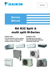
Daikin M Series Service Manual (132 pages)
RA R32 Split & multi split
Brand:
Daikin
| Category:
Air Conditioner
| Size: 49.58 MB
Table of Contents
Table of Contents
3
Part 1. Introduction
9
Version Log
9
Safety Precautions
10
Meaning of Symbols
10
Warnings
10
Cautions
12
Information
13
General Operation
14
How to Use
15
Interactive Information Flow
15
Parts of the Book
16
Appendices
16
The Introduction Chapter
16
The Maintenance Chapter
16
The Repair Chapter
16
The Troubleshooting Chapter
16
Contact Information
16
Part 2. Troubleshooting
17
Error Codes Check
17
Error Codes Via Remote Controller
17
General
17
How to Clear Error Codes
17
History of Error Codes
18
Error Codes Via Outdoor Unit PCB2 (Service PCB) (3MXM-N(9), 4MXM-N(9), 5MXM-N(9))
19
How to Retrieve Error Codes
19
Error Based Troubleshooting
20
Indoor Unit
21
A0-00" - Detection of Refrigerant Leak (Only for FVXM-F Model)
21
A1-00" - PCB Abnormality
21
A1-01" - PCB Abnormality
22
A5-00" - Freeze-Up Protection / Heating Peak Cut Control
22
A6-00" - Fan Motor Abnormality
23
C4-00" - Liquid Pipe Thermistor for Heat Exchanger Abnormality
23
C7-00" - Front Panel Open/Close Fault
24
C9-00" - Suction Air Thermistor Abnormality
24
00" - Abnormality of Refrigerant Leakage Sensor (Only for FVXM-F Model)
24
UH-00" - Anti-Icing Function in Other Room(S)
25
Outdoor Unit
26
E1-00" - Outdoor Unit PCB Abnormality
26
E3-00" - Discharge Pressure Abnormality
26
E5-00" - Compressor Motor Lock or Overheated
27
E6-00" - Compressor Motor Lock
27
E7-00" - Fan Motor Abnormality
28
E8-00" - Compressor Overcurrent Detection
29
EA-00" - 4-Way Valve Abnormality
29
F3-00" - Discharge Pipe Temperature Abnormality
30
F6-00" - High Pressure Abnormality or Refrigerant Overcharge
30
F8-00" - System Shutdown Due to Compressor Internal Temperature Abnormality
31
H0-00" - Compressor Sensor System Abnormality
31
H6-00" - Position Detection Sensor Abnormality
32
H8-00" - Compressor Input (CT) System Abnormality
32
H9-00" - Outdoor Air Temperature Thermistor Abnormality
33
J3-00" - Discharge Pipe Thermistor Abnormality
33
J6-00" - Outdoor Heat Exchanger Thermistor Abnormality
33
J8-00" - Liquid Pipe Thermistor Abnormality
34
J9-00" - Gas Pipe Thermistor Abnormality
34
L1-00" - Outdoor Main PCB Abnormality
35
L3-00" - Switch Box Temperature Abnormality
36
L4-00" - Inverter Radiating Fin Temperature Abnormality
36
L5-00" - Inverter Instantaneous Overcurrent (AC Output)
37
P4-00" - Radiating Fin Temperature Sensor Abnormality
38
System
39
U0-00" - Refrigerant Shortage
39
U2-00" - Power Supply Abnormality or Instantaneous Power Failure
39
U3-00" - Check Operation Not Executed or Transmission Error
40
U4-00" - Transmission Abnormality between Indoor Unit and Outdoor Unit
41
U5-00" - Malfunction of Transmission between Indoor Unit and Remote Controller
41
U7-00" - Transmission Outdoor Unit-Outdoor Unit Abnormality
42
UA-00" - Improper Combination of Indoor Unit and Outdoor Unit
42
UF-00" - Wiring and Piping Mismatch
43
Symptom Based Troubleshooting
44
Operation Does Not Start
44
Operation Sometimes Stops
44
Some Indoor Units Do Not Operate
45
Operation Starts but the Unit Does Not Cool/Heat
45
Operating Noise and Vibrations
45
Abnormal High Pressure
46
Abnormal Low Pressure
46
Indoor Fan Starts Operating but the Compressor Does Not Operate
47
Operation Starts and the Unit Stops Immediately
48
Operation Stops, Unit Cannot Start for a While
48
Indoor Unit
48
Outdoor Unit
48
System
48
Others
48
Component Checklist
49
Indoor Unit
50
Fan Motor
50
Outdoor Unit
51
4-Way Valve
51
Compressor
53
Electronic Expansion Valve
55
Fan Motor
57
Main PCB
57
Refrigerant Thermistors
58
Part 3. Repair
61
Refrigerant Repair Procedures
61
Refrigerant Piping Handling
61
Recovery Procedure
61
Outdoor Unit Casing
61
Refrigerant Pump down
63
Piping Repair Procedures
64
Service Tools
65
Unit Specific Repair Procedures
66
Indoor Unit
67
Replacing R32 Sensor (Only for FVXM-F Model)
67
Outdoor Unit
69
Basic Removal
69
Replacing Switch Box
72
Replacing 4-Way Valve Body
74
Replacing 4-Way Valve Coil
76
Replacing Compressor
77
Replacing DC Fan Motor Assembly
80
Replacing Expansion Valve Body
82
Replacing Expansion Valve Motor
83
Replacing Main PCB
85
Replacing Propeller Fan Blade Assembly
86
Replacing Thermistors
87
Setting Test Mode for Inverter Checker
88
Part 4. Maintenance
89
Indoor Unit
89
General Maintenance
89
To Clean the Air Filters
90
Outdoor Unit
91
General Maintenance Outdoor Unit
91
Part 5. Appendix
93
Field Setting
95
Indoor Unit
95
Indoor Fan Control During Thermostat off in Cooling
95
Brightness Setting of Multi-Coloured Lamp of the Indoor Unit
96
Heat Only Mode
96
ON/OFF Button on the Indoor Unit
96
Auto Restart ON/OFF
97
Outdoor Unit
98
Facility Setting for Outdoor Split Units
98
Multi Split Outdoor
98
Reducing Maximum Sound Levels
101
Remote Controller
101
Wiring Diagram
102
Indoor Unit
102
Fna-A
102
Ftxm20-42M, Ftxm20-42N, Ctxm-M, Ctxm-N, Atxm20-35M, Atxm20-35N
103
Ftxm50-71M, Ftxm50-71N, Atxm50M, Atxm50N
103
Ftxm20-35M9
104
Outdoor Unit
105
2Mxm50M9
105
3Mxm68M, 3Mxm68N(9)
105
4Mxm-M, 4Mxm-N
106
5Mxm-M, 5Mxm-N
106
Rxj20-35M(9)
107
Rxj50M
107
Rxm20-35M, Arxm-M
108
Rxm42-50M
108
Rxm60-71M
109
Rxm71M
109
Rxj50N
110
Rxm20-35N9, Arxm25-35N9
110
Rxm42N9, Arxm50N9
111
Rxm50-60N9
111
2Mxm40M
112
Rxm71N
112
3Mxm40-52M
113
Rxm20-35M9, Arxm25-35M9
113
Arxm50N
114
Rxm42-50M9, Arxm50M9
114
3Mxm40-52N, 3Mxm52N9
115
Field Wiring
115
Piping Diagram
116
Indoor Unit
116
Fna-A
116
Ftxm20-35M, Ftxm20N, Ctxm-M, Ctxm-N, Atxm20-35M, Atxm20N, Ftxp35M9
116
Ftxm25-35N, Atxm25-35N
116
Ftxm42M
117
Ftxm42N
117
Ftxm50-60M, Ftxm50-60N, Atxm50M, Atxm50N
117
Ftxm71M, Ftxm71N
118
Ftxm20-25M9
118
Outdoor Unit
119
2Mxm40M
119
3Mxm68M, 3Mxm68N(9)
119
4Mxm68M, 4Mxm68N
120
5Mxm-M, 5Mxm-N
120
Rxj20-35M(9)
121
Rxj50M
121
Rxm20-35M, Rxm20-35M9, Arxm-M, Arxm25-35M9, Arxm25-35N9
122
Rxm42-50M, Rxm42-50M9, Arxm50M9
122
Rxm60M, Rxm60M9
123
Rxm71M
123
Rxj50N
124
Rxm20-35N9
125
Rxm42-60N9, Arxm50N, Arxm50-60N9
125
Rxm71N
126
2Mxm-M9
126
3Mxm40-52M, 3Mxm40-52N, 3Mxm52N9
127
4Mxm80M, 4Mxm80N
127
Component Overview of Unit
128
Indoor Unit
128
Outdoor Unit
128
Product Specific Information
129
Error Codes
129
E7-00" - Fan Motor Abnormality
129
EA-00" - Malfunction of 4-Way Valve
129
F3-00" - Discharge Pipe Temperature Abnormality
129
L3-00" - Switch Box Temperature Abnormality
129
L4-00" - Inverter Radiating Fin Temperature Abnormality
129
Component Checklist
129
Switch Box
129
Indoor Unit
129
Field Information Report
130
Advertisement
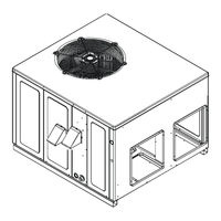
Daikin M Series Installation Instructions Manual (48 pages)
Single Package Gas-Electric Heating & Cooling Unit
Brand:
Daikin
| Category:
Accessories
| Size: 5.25 MB
Table of Contents
Table of Contents
2
Replacement Parts
3
Ordering Parts
3
Safety Instructions
3
To the Installer
3
General Information
5
Transportation Damage
5
Unit Location
6
All Installations
6
Ground Level Installations Only
6
Rooftop Installations Only
6
Roof Curb Installations Only
7
Rigging Details
7
Gas Piping
7
High Altitude Derate (U.s. Installations Only)
8
Piping
8
Gas Piping Checks
9
Propane Gas Installations
9
Tanks and Piping
9
Electrical Wiring
10
Thermostat Location
10
Single Stage Thermostat - Two-Stage Models
10
Unit Voltage
11
Circulating Air and Filters
11
Airflow Conversion
11
Ductwork
12
Filters
12
Venting
12
Flue Hood Installation
12
Installation - Flue Hood Exhaust
12
Installation - Combustion Air Intake Hood
13
Condensate Drain
13
Condensate Drain Connection
13
Normal Sequence of Operation
13
Heating
13
Cooling
14
Fan Only
14
Startup, Adjustments, and Checks
14
Heating Startup
14
Gas Supply Pressure Measurement
15
Gas Manifold Pressure Measurement and Adjustment
16
Cooling Startup
19
Checking Subcooling
19
Checking Superheat
19
Troubleshooting
20
Ignition Control Error Codes
20
Abnormal Operation - Heating
20
Abnormal Operation - Cooling
22
Maintenance
22
Filter Replacement or Cleaning
22
Cabinet Finish Maintenance
22
Clean Outside Coil (Qualified Servicer Only)
22
Condenser, Evaporator, and Induced Draft Motors
22
Flame Sensor (Qualified Servicer Only)
22
Flue Passages (Qualified Servicer Only)
22
Cleaning Flue Passages (Qualified Servicer Only)
23
Main Burner Flame (Qualified Servicer Only)
23
Cleaning Burners
23
Accessories and Functional Parts
23
Sheet Metal Accessories
23
Functional Parts
24
General Information
24
Blower Performance Data
25
Ignition Control Diagnostic Indicator Chart
29
(Single Stage Models Only)
29
Heating Timing Chart
29
Cooling Timing Chart
29
Ignition Control Diagnostic Indicator Chart
30
(Two-Stage Models Only)
30
Heating Timing Chart
30
Cooling Timing Chart
30
Appendix
31
Unit Dimensions
31
Wiring Diagrams
32
Homeowner's Routine Maintenance
44
Start-Up Sheet
45
Daikin M Series Service And Troubleshooting (51 pages)
13.4 SEER2 Single Package Dual Fuel Gas-Electric Heating & Cooling Units
Brand:
Daikin
| Category:
Air Conditioner
| Size: 3.63 MB
Table of Contents
Table of Contents
1
Important Information
2
Product Identification
5
System Operation
7
Scheduled Maintenance
15
Servicing
15
Checking Voltage
17
Checking Wiring
17
Checking Thermostat and Wiring
17
Indoor Blower Motor
17
Checking Transformer and Control Circuit
18
Checking Contactor And/Or Relays
18
Checking Contactor Contacts
18
Checking Fan Relay Contacts
19
Checking High Pressure Control
19
Checking Low Pressure Control
19
Checking Capacitor
19
Capacitance Check
20
Checking Fan and Blower Motor Windings (Psc Motors)
21
Checking Eem Motors
21
Checking Compressor
22
Resistance Test
22
Ground Test
23
Operation Test
23
Locked Rotor Test
24
Testing Crankcase Heater (Optional Item)
24
Checking Reversing Valve and Solenoid
24
Testing Defrost Control
25
Testing Defrost Thermostat
25
Refrigeration Repair Practice
25
Standing Pressure Test
26
Leak Testing (Nitrogen or Nitrogen-Traced)
26
System Evacuation
26
Deep Vacuum Method (Recommended)
26
Triple Evacuation Method (Alternate)
27
Charging
27
Refrigerant Charge Check
28
Checking Superheat
28
Checking Subcooling
28
Checking Compressor Efficiency
29
Fixed Orifice Restriction Devices
32
Checking Equalization Time
32
Checking Restricted Liquid Line
32
Refrigerant Overcharge
32
Non-Condensables
32
Compressor Burnout
33
Suction Line Drier Clean-Up Method
33
Reversing Valve Replacement
33
Checking External Static Pressure
34
Adjusting Airflow
34
Checking Temperature Rise
34
Testing Primary Limit Control
35
Testing Auxiliary Limit
35
Checking Flame Rollout Switch
36
Testing Inducer Motor
37
Testing Gas Valve
37
Checking Main Burners
38
Checking Orifices
38
Checking Gas Pressure
38
Gas Inlet Pressure Check
39
Checking for Delayed Ignition
40
Checking for Flashback
40
Checking Pressure Control
40
Pressure Switch Operation
40
High Altitude Application
41
Testing Ignition Control Module
41
Checking Flame Sensor
43
Troubleshooting
46
Wiring Diagrams
48
Advertisement
Daikin M Series Installation Instructions Manual (28 pages)
Self-Contained Package Heat Pump Units
Brand:
Daikin
| Category:
Heat Pump
| Size: 4.54 MB
Table of Contents
Table of Contents
2
To the Installer
2
Shipping Inspection
2
Checking Product Received
2
Message to the Homeowner
2
Replacement Parts
2
Ordering Parts
2
Important Safety Instructions
3
Recognize Safety Symbols, Words and Labels
3
Codes and Regulations
3
General
3
EPA Regulations
3
National Codes
4
Major Components
4
Installation
4
Pre-Installation Checkpoints
4
Unit Location
4
Ground Level Installation
5
Unit Precautions
5
Roof Curb Installations Only
5
Clearances
6
Roof Top Duct Connections
6
Roof Top Installation
6
Horizontal Discharge
7
Rigging Details
7
Rigging Removal
8
Electrical Wiring
8
Low Voltage Control Wiring
10
Circulating Air and Filters
10
Ducting
10
Condensate Drain Piping
10
Horizontal Drain
10
Vertical Drain
10
Cleaning
11
Startup, Adjustments, and Checks
11
Air Flow Adjustments
12
EEM - Standard Static Drive Motor
12
Superheat and Subcooling
12
Checking Subcooling
12
Checking Superheat
13
Superheat Adjustment
13
Refrigerant Charge Check
13
Start-Up Procedures and Checklists
13
Air Conditioner Start-Up Procedure
13
Heat Pump Start-Up Procedure
14
Final System Check
14
Heat Pump Operation
14
Cooling Cycle
14
Heating Cycle
15
Defrost Control
15
M a I N T E N a N C
17
Wiring Examples
18
Appendix A Blower Performance Table
19
Appendix C Unit Dimensions
21
Appendix D Air Flow for Electric Heat
22
Wiring Diagram
23
Start-Up Checklist
24
Advertisement
Related Products
Daikin Maverick I MPS H05C
Daikin Maverick I MPS A05C
Daikin Maverick II MPS062E
Daikin Maverick I MPSA010D
Daikin MKB50TVMG
Daikin MKM105PV1G
Daikin MKS90QVMG
Daikin MXM-M(9)
Daikin MTKL50UV16V
Daikin MXS-FV1B_F2V1B
Daikin Categories
Air Conditioner
Heat Pump
Remote Control
Chiller
Fan
More Daikin Manuals
Login
Sign In
OR
Sign in with Facebook
Sign in with Google
Upload manual
Upload from disk
Upload from URL