
Related Manuals for Sunrise Medical DeVilbiss 505DZ


Summary of Contents for Sunrise Medical DeVilbiss 505DZ
- Page 1 DeVilbiss 5 Liter Oxygen Concentrator Models 505DZ, 505DS, 505CZ, & 505CS Service Manual CAUTION-Federal (U.S.A.) law restricts this device to sale by or on the order of a physician.
-
Page 2: Table Of Contents
T A B L E O F C O N T E N T S General Information Introduction ......................................3 Important Safeguards.....................................3 Safety Precautions and General Warnings ............................3 Theory of Operation.....................................3 Operation/Installation Operation .........................................4 Microprocessor-Controlled Pressure-Sensing System........................4 OSD Option ......................................4 Exterior and Interior Parts Figures ..............................5 Operating the DeVilbiss Oxygen Concentrator ..........................11 Performing Initial Inspection ................................11 Suggested Patient Setup..................................12... -
Page 3: General Information
G E N E R A L I N F O R M AT I O N Introduction Safety Precautions and This service manual was created for Sunrise Medical qualified General Warnings service technicians to define the proper maintenance, service, and repair procedures on the DeVilbiss 5 Liter Oxygen Federal (U.S.A.) law restricts this device to sale by or on... -
Page 4: Operation/Installation
NOTE – Sunrise Medical reserves the right to alter or change the design of the DeVilbiss Oxygen Concentrator series. Hence, slight differences in construction or components may exist than what is described herein. -
Page 5: Exterior And Interior Parts Figures
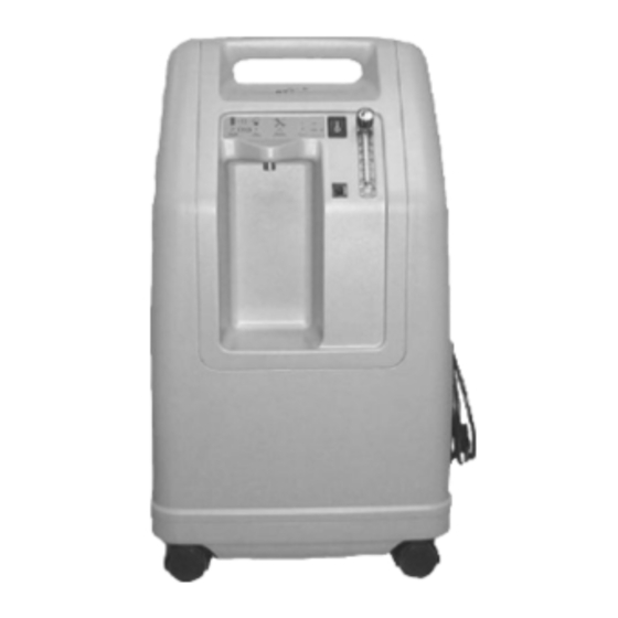
O P E R A T I O N / I N S T A L L A T I O N The following figures will help familiarize you with the exterior of the DeVilbiss 5 Liter Oxygen Concentrator. Oxygen outlet port Light panel Power switch Flow meter... - Page 6 O P E R A T I O N / I N S T A L L A T I O N Cabinet screws Filter door Air filter Communication port (OSD units only) Rear cover Rating label Cabinet screw Exterior Back View Figure 2 Rear cover Cabinet screw...
- Page 7 O P E R A T I O N / I N S T A L L A T I O N PC board 1/4" I.D. hose Hose clamp Accumulator tank Hose clamp Fitting (top of sieve bed) 1/4" I.D. hose Intake silencer valve wire...
- Page 8 O P E R A T I O N / I N S T A L L A T I O N Hour meter Oxygen sensor Accumulator tank assembly (OSD units only) Communication port Compressor filter (OSD units only) Silicon tubing Compressor Hose clamp Screw...
- Page 9 O P E R A T I O N / I N S T A L L A T I O N Screw (bib) Pressure regulator Flow meter Accumulator tank Right sieve bed Tab connecting bib to compressor housing Bib tab Housing Caster Caster...
- Page 10 O P E R A T I O N / I N S T A L L A T I O N Power switch Final bacteria filter Light panel ribbon connector Screw (outlet port) Flow meter Oxygen outlet port Bracket/Spring clip 1/8"...
-
Page 11: Operating The Devilbiss Oxygen Concentrator
1 and bed 2 at 5 LPM. Flow meter NOTE—If the unit fails to operate properly (i.e., oxygen con- centration or cycle times are not within specification) or if internal damage is found, contact the Sunrise Medical Service Department at 1-800-338-1988. Circuit breaker Figure 10... -
Page 12: Suggested Patient Setup
Oxygen WARNING—Electric Shock Hazard. Only qualified tubing Sunrise Medical homecare providers may remove the cabinet. Attach the appropriate oxygen accessories (oxygen tubing or humidifier) to the oxygen outlet. NOTE – A maximum of 50 feet (15 meters) of tubing (plus 3 feet (1meter) cannula) is allowed between the concentrator and the patient. -
Page 13: Maintenance
M A I N T E N A N C E Routine Patient Maintenance Periodic Homecare Provider Preventative The oxygen patient should perform the following maintenance: Maintenance Oxygen Humidifier (reusable bottles only) Every DeVilbiss oxygen concentrator is tested at the factory. The patient should clean the humidifier bottle daily.The patient To assure continued trouble-free performance, the following should follow the instructions supplied by the manufacturer. -
Page 14: Between Patient Maintenance
M A I N T E N A N C E NOTE – Make sure the filter end marked “IN” is toward Rear cover compressor. Attach the hose to the outlet fitting end of the filter Filter door and secure with hose clamp. Leak test the HEPA filter fittings. -
Page 15: Patient Alert & Diagnostic System
P A T I E N T A L E R T & D I A G N O S T I C S Y S T E M Patient Alert System The DeVilbiss Concentrator patient alert system will detect unit component failure as well as restricted flow situations. This system is comprised of both visible and audible alarms which signal the patient if a malfunction should occur. - Page 16 P A T I E N T A L E R T & D I A G N O S T I C S Y S T E M The diagnostic system will also keep the last diagnostic light failure sequence in memory.This gives the service technician the ability to view the cause of a unit shutdown after the unit has been turned off.
- Page 17 P A T I E N T A L E R T & D I A G N O S T I C S Y S T E M IMPORTANT Shown below are the failure combinations for the diagnostic service lights D17, D16, and D18 top to bottom and their respective meanings.
-
Page 18: Troubleshooting
T R O U B L E S H O O T I N G Normal Operating Sequence When pressure test gauges are attached to the test points on the manifold, the following cycling sequence should be observed. Most types of unit malfunctions will cause a deviation in this sequence and possibly a unit shutdown or a change in cycle times. When the concentrator is turned “On,”... -
Page 19: Simplified Troubleshooting
T R O U B L E S H O O T I N G Simplified Troubleshooting The key to simple troubleshooting is to recognize which type of problem exists and select the most effective approach to solving the problem. The different types of problems and the approaches for solutions are as follows: Type I-Unit runs for a while and shuts off. - Page 20 T R O U B L E S H O O T I N G Symptom Visible Alarm Audible Alarm Compressor Power Light Other Symptoms Possible Cause Possible Remedy Pulsating air noise. 1. Intake filter not in place or defective. 1.
- Page 21 T R O U B L E S H O O T I N G Symptom Visible Alarm Audible Alarm Compressor Power Light Blinking Pulsing Other Symptoms Possible Cause Possible Remedy Fan off. 1. Line cord not properly installed or defective. 1a.
- Page 22 T R O U B L E S H O O T I N G Symptom Visible Alarm Audible Alarm Compressor Power Light Other Symptoms Possible Cause Possible Remedy Fan operating. 1. Wiring harness disconnected/defective. 1. Reconnect/replace wiring harness. 2. Loose compressor wire. 2.
-
Page 23: Troubleshooting Chart
T R O U B L E S H O O T I N G OSD troubleshooting Symptom Visible Alarm Audible Alarm Compressor Power Light Other Symptoms Possible Cause Possible Remedy No OSD lights are 1. Connector off between OSD and PC board. 1. -
Page 24: Component Testing, Repair, And Replacement
C O M P O N E N T T E S T I N G , R E P A I R & R E P L A C E M E N T Component Testing, Repair & Replacement Proper Repair Procedures The DeVilbiss 5 Liter Oxygen Concentrator is designed for ease of service. -
Page 25: Leak Testing
WARNING – Electric shock hazard. Do not remove cabinet. The cabinet may only be removed by a qualified Sunrise Medical homecare provider. WARNING – Disconnect the power cord from the wall outlet before attempting repairs on the unit. Extra care should be taken if it is necessary to operate the unit with the cabinet removed. - Page 26 C O M P O N E N T T E S T I N G , R E P A I R & R E P L A C E M E N T Cabinet screws Rear cover Cabinet screw Figure 18 The majority of all the servicing and repairs can be done without removing the front bib.
-
Page 27: Power Cord
C O M P O N E N T T E S T I N G , R E P A I R & R E P L A C E M E N T To remove the bib completely (Figure 20) Disconnect the ribbon connector from the PC board. -
Page 28: Flow Meter
PSI ± .5 PSI (60 kPa ± 3.5 kPa) with gauge outlet blocked, Figure 22 adjustment to the pressure regulator may be required. If so, call Sunrise Medical Technical Service at 1-800-333- 4000. NOTE – Ensure no leaks exist before adjusting pressure regulator. -
Page 29: Sieve Bed Check Valves
C O M P O N E N T T E S T I N G , R E P A I R & R E P L A C E M E N T To replace pressure regulator (Figure 23): Ensure the unit is unplugged from the wall outlet. - Page 30 C O M P O N E N T T E S T I N G , R E P A I R & R E P L A C E M E N T To check accumulator pressures (Figure 24): Ensure the unit is “Off.”...
-
Page 31: Final Check Valve
C O M P O N E N T T E S T I N G , R E P A I R & R E P L A C E M E N T Final Check Valve Another check valve is located between the final bacteria filter and the oxygen outlet fitting.This check valve allows only oxygen to flow out of the unit.When the unit is turned off and oxygen flow stops, the check valve closes to prevent water from being drawn into the unit. -
Page 32: Molecular Sieve Beds
C O M P O N E N T T E S T I N G , R E P A I R & R E P L A C E M E N T Molecular Sieve Beds The two molecular sieve beds alternately remove the nitrogen from the air passing through them and provide the patient with a con- stant supply of oxygen. - Page 33 C O M P O N E N T T E S T I N G , R E P A I R & R E P L A C E M E N T NOTE—If the short cycle (D16 or D16 and D18) alarm has been activated, it must be determined whether the problem is with the sieve beds, a failure of the four- way to shift, or a restriction of flow.
-
Page 34: Compressor
C O M P O N E N T T E S T I N G , R E P A I R & R E P L A C E M E N T Compressor The DeVilbiss 5 Liter Oxygen Concentrator uses a double-head, oil-free compressor. The compressor is secured to a metal plate with four rubber motor mounts. - Page 35 C O M P O N E N T T E S T I N G , R E P A I R & R E P L A C E M E N T To test the compressor for proper output: NOTE—If the compressor is not providing a high enough output, the cycle time will be long and the patient alert system might be activated.
- Page 36 C O M P O N E N T T E S T I N G , R E P A I R & R E P L A C E M E N T Pressure intake fitting Compressor Pressure relief valve Compressor mounting plate Figure 32...
- Page 37 C O M P O N E N T T E S T I N G , R E P A I R & R E P L A C E M E N T Remove the two hex nuts that secure the mounting plate to the front of the compressor housing (Figure 34). These nuts are located on each side of the four-way valve.
- Page 38 C O M P O N E N T T E S T I N G , R E P A I R & R E P L A C E M E N T To replace the compressor reed valve (Figure 35): To replace Teflon ring (Figure 35): Remove screw holding compressor reed valve in Remove screws from top of piston.
- Page 39 C O M P O N E N T T E S T I N G , R E P A I R & R E P L A C E M E N T Thomas Q2 Compressor (exploded view) 1 Connecting rod, eccentric 10 Head and bearing assembly...
- Page 40 C O M P O N E N T T E S T I N G , R E P A I R & R E P L A C E M E N T To replace compressor (Figure 36): NOTE—For mounting plate and motor mount removal, refer to sections below.
-
Page 41: Cooling Fan
C O M P O N E N T T E S T I N G , R E P A I R & R E P L A C E M E N T Cooling Fan The cooling fan provides a constant air flow to cool the compressor. A defective cooling fan may cause the compressor’s internal thermo-protective device to activate and shut the compressor off. - Page 42 C O M P O N E N T T E S T I N G , R E P A I R & R E P L A C E M E N T The four-way valve, while operating pneumatically, uses an external pilot valve that allows pressure to shift the spool inside the four- way.This pilot valve receives a signal (12-15 VDC) from the PC board causing it to open and allowing pilot pressure to activate the four-way.When the four-way is activated, the left sieve bed will pressurize.
- Page 43 C O M P O N E N T T E S T I N G , R E P A I R & R E P L A C E M E N T If the left bed does pressurize first, observe whether pressure is shifted to the right bed once the shift point pressure is reached or if the left bed proceeds to pressurize again.
- Page 44 C O M P O N E N T T E S T I N G , R E P A I R & R E P L A C E M E N T To remove four-way valve (Figure 41): Unplug the unit from the wall outlet.
- Page 45 C O M P O N E N T T E S T I N G , R E P A I R & R E P L A C E M E N T To clean the four-way valve (Figure 42): Remove the two allen head valve retaining screws from the top of the four-way valve.The top of the valve body can now be removed along with the pilot valve.The valve manifold will remain on the unit.
-
Page 46: Purge Valve
C O M P O N E N T T E S T I N G , R E P A I R & R E P L A C E M E N T Purge Valve Place the test leads of a volt meter across the terminals located on the pilot valve. -
Page 47: Pilot Pressure System
C O M P O N E N T T E S T I N G , R E P A I R & R E P L A C E M E N T Carefully push sleeve into valve body (turning it slightly) so To test pilot pressure: you do not cut or nick the o-rings.To ensure proper Remove the front cabinet. -
Page 48: Manifold Assembly
C O M P O N E N T T E S T I N G , R E P A I R & R E P L A C E M E N T Manifold Assembly The manifold assembly is located on the front of the unit below the bib and has two externally mounted valves, the four-way and purge.These valves can be removed separately for cleaning or replacement when necessary.The base of the manifold assembly does not have to be removed in this case. -
Page 49: Printed Circuit Board
C O M P O N E N T T E S T I N G , R E P A I R & R E P L A C E M E N T To replace manifold: fitting at the top of the manifold. Remove the four-way and purge valves from the defective Install the right sieve bed oxygen supply hose to the top manifold and install them on the new manifold base. -
Page 50: Capacitor
C O M P O N E N T T E S T I N G , R E P A I R & R E P L A C E M E N T To remove and replace the PC board (Figure 45): WARNING—Electric Shock Hazard:When replacing the Ensure the unit is unplugged from the wall outlet. -
Page 51: Pneumatic Diagram
P N E U M A T I C D I A G R A M... -
Page 52: Wiring Diagram
W I R I N G D I A G R A M FOR MODELS EQUIPPED WITH OXYGEN SENSOR ONLY OXYGEN SENSOR ASS'Y BLACK J1-1 BLUE COMMUNICATION J1-2 PORT WHITE/RED J1-3 WHITE/RED WHITE/RED J2-1 J2-7 ORANGE ORANGE J2-2 J2-8 WHITE/RED J2-9 ORANGE WHITE/RED... -
Page 53: Specifications
NOTE – Specifications subject to change without notice. Between sea level and 5000 ft (1500m) at 70°F (21°C) ambient across the operating voltage range. From 5000 ft (1500m) to 13100 ft (4000m) the end user should check with their Sunrise Medical provider for suitability. -
Page 54: Ordering Information
HAVE TO BE RETURNED TO THE FACTORY. Before returning parts or units to the factory, call the Sunrise Medical Returns (1-800-333-4000) to obtain a return authorization number. Include in the package a note indicating the return authorization number along with your company name, address, phone number, and account number.The return authorization number should also be written on the outside of the package. -
Page 55: Parts List
P A R T S L I S T Description Part Number Description Part Number Accessories Hose and Tubing 1/16" ID Blue..............444-526 Bubble Humidifier ..............HUM16 1/8" ID Blue ...............444-554 Cannula (disposable: 50/case..........CAN00 1/4" ID Blue ...............444-525 Cannula w/7 ft (2.1m) 1/2"... -
Page 56: Warranty Information
Under the Optional Extended Warranty, the equip- provider and/or an Authorized Sunrise Medical Service Center. ment is warranted by Sunrise Medical to be free from defects in NOTE – This warranty does not obligate Sunrise Medical to workmanship and materials for a period of five years, except as... - Page 57 Sunrise Home Healthcare Group 7477 East Dry Creek Parkway Longmont, Colorado 80503 (800) 333-4000 In Canada (800) 263-3390 © 1999 Sunrise Medical LT-1692 Rev. B...
Need help?
Do you have a question about the DeVilbiss 505DZ and is the answer not in the manual?
Questions and answers