Table of Contents
Advertisement
Quick Links
Advertisement
Table of Contents

Subscribe to Our Youtube Channel
Related Manuals for u-blox EVK-JODY-W3


Summary of Contents for u-blox EVK-JODY-W3
- Page 1 EVK-JODY-W3 Evaluation kit for JODY-W3 host-based modules User guide Abstract This document describes how to set up and use the EVK-JODY-W3 evaluation kit to evaluate JODY-W3 series multiradio modules with Wi-Fi and Bluetooth. UBX-20030840 - R04 C1 – Public www.u-blox.com...
- Page 2 The information contained herein is provided “as is” and u-blox assumes no liability for its use. No warranty, either express or implied, is given, including but not limited to, with respect to the accuracy, correctness, reliability and fitness for a particular purpose of the information.
-
Page 3: Table Of Contents
EVK-JODY-W3 - User guide Contents 1.1 Overview ................................ 4 1.2 Kit includes ..............................6 1.3 Software ................................ 7 1.4 System requirements ..........................7 1.5 Operating conditions ..........................8 3.1 Block diagram ............................11 3.2 Jumpers and connectors ........................12 3.2.1 Jumper and switch configuration options .................. 13 3.2.2 Jumper conventions ........................ -
Page 4: Overview
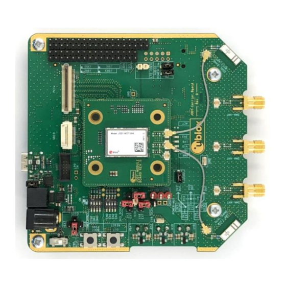
PCIe or SDIO for Wi-Fi, SDIO or high-speed UART for Bluetooth, and PCM/I2S for Bluetooth audio. EVK-JODY-W3 allows an external host processor to access several practical features for testing and evaluating the Wi-Fi and Bluetooth connectivity supported in JODY-W3 series modules, including: •... - Page 5 EVK-JODY-W3 - User guide Figure 1 shows the main components of the EVK-JODY-W3 evaluation board. U.FL coaxial Evaluation PCM/I2S GPIOs interface board (EVB) cable connector Internal dual-band antenna PCIe connector SDIO connector SMA connectors for USB connector external antennas through FTDI...
-
Page 6: Kit Includes
EVK-JODY-W3 - User guide 1.2 Kit includes Table 2 shows the various components included in the EVK-JODY-W3. Part Description Outline Evaluation Evaluation board for the JODY-W3 series modules. board The board includes SMA antenna connectors that (EVB) connect to external antennas for Wi-Fi and Bluetooth. It also supports two internal dual-band Wi-Fi/Bluetooth antennas. -
Page 7: Software
Wi-Fi and Bluetooth features, see also the JODY-W3 system integration manual [2] and the NXP User Manual UM11490 [6]. Contact your local u-blox support team for information about additional software options for the JODY-W3 series modules. 1.4 System requirements The evaluation kit has the following system requirements: •... -
Page 8: Operating Conditions
EVK-JODY-W3 - User guide 1.5 Operating conditions Table 3 describes the recommended operating conditions for the EVK-JODY-W3. For more information about power supply requirements, see also the JODY-W3 series data sheet [1]. Symbol Parameter Min. Typ. Max. Units 3V3 / VDD_PCIE Module 3.3 V power supply voltage from external... - Page 9 EVK-JODY-W3 - User guide Getting started This chapter describes the basic settings and procedures to get started with EVK-JODY-W3. ☞ An overview of the EVB and its main connectors is shown in Figure 1. For more detailed description of the available connectors and configuration options, see Board description.
- Page 10 EVK-JODY-W3 - User guide For SDIO connection, connect the supplied micro SDIO adapter card with the flat cable to the SDIO connector (J204) on the EVB, as shown in Figure 3. Insert the adapter card into an SDIO connector of the host system. The SDIO interface can be used for Wi-F and optionally Bluetooth communication with the JODY-W3 series module.
-
Page 11: Block Diagram
UART to Power supply 3x SMA connectors JODY-W3 DC-DC module 2x internal Bootstrap dual-band configuration antennas Control lines Audio interface Audio and GPIOs (PCM/I2S) codec Figure 4: EVK-JODY-W3 block diagram UBX-20030840 - R04 Board description Page 11 of 29... -
Page 12: Jumpers And Connectors
J203 (PCIe) J204 (SDIO) SW503 SW501 SW500 JODY-W3 module board J401/ J402 Input voltage J206 (bottom selection J411 (LEDs) audio jack) ANT400 ANT401 J406 J408 J410 Figure 5: EVK-JODY-W3 jumpers and connectors UBX-20030840 - R04 Board description Page 12 of 29... -
Page 13: Jumper And Switch Configuration Options
EVK-JODY-W3 - User guide 3.2.1 Jumper and switch configuration options Table 4 provides a summary of the connectors and jumpers used to configure EVK-JODY-W3. Designator Connector Description J104-J106 Power supply selection Jumper settings for external power supply selection. (power mux) -
Page 14: Power Supply Configuration
EVK-JODY-W3 - User guide 3.3 Power supply configuration JODY-W3 series modules must be supplied with 1.8 V (1V8), 3.3 V (3V3), and a VIO voltage that can be either 1.8 V or 3.3 V. The power supply for the EVB can be provided over the different host interfaces or from external sources. -
Page 15: Selecting The Evb Power Supply
EVK-JODY-W3 - User guide To operate the JODY-W3 EVB, the external power supply source (power mux) and input voltage levels to the module must be configured using jumpers on the EVB. The power supply tree, including the jumpers on the EVB, is shown in Figure 8. See also Jumpers and connectors. -
Page 16: Selecting The Module Input Voltage
EVK-JODY-W3 - User guide Table 5 shows the (J104–J106) jumper positions for selecting the power supply source for the EVB. Power supply source Jumper configuration 3.3 V from PCIe interface Use the M.2 or mini-PCIe adapter with the flat cable to connect to the host system. - Page 17 EVK-JODY-W3 - User guide The input voltage options for selecting the module supply are described in Table 6. Designator Module supply Source Can be connected to 3V3_DCDC or 3V3_EXT Can be connected to 3V3_VIO, 1V8_VIO, or VIO_EXT Can be connected to 1V8_DCDC or 1V8_EXT Table 6: Input voltage options Table 7 describes the different options for selecting the module input voltages using jumpers J1-J7.
-
Page 18: Bootstrapping
EVK-JODY-W3 - User guide 3.4 Bootstrapping JODY-W3 supports the following host interface combinations: • PCIE-UART mode: Commands and data for the Wi-Fi traffic are transferred through the PCIe bus to the module. The Bluetooth traffic uses the high-speed UART interface. -
Page 19: Pcie Interface
EVK-JODY-W3 - User guide 3.5 PCIe interface The EVB can be connected through a PCIe connector for Wi-Fi communication with the host system. Adapters for host-side M.2 Key E and mini-PCIe connectors are supplied in the kit. The PCIe host interface connector (J203) is shown in Figure 12. -
Page 20: Sdio Interface
EVK-JODY-W3 - User guide 3.6 SDIO interface The EVB can be connected through a micro SDIO connector for Wi-Fi communication with the host system. The SDIO connector can optionally be used for Bluetooth The SDIO host interface connector (J204) is shown in Figure 13. -
Page 21: Bluetooth Host Interface
EVK-JODY-W3 - User guide 3.7 Bluetooth host interface The Bluetooth UART host interface of the JODY-W3 series module can be accessed either directly through the UART pins on J305, or through the USB type-C connector through a USB-to-UART bridge (default). -
Page 22: Antenna Interfaces
See also EVK-JODY-W374 antenna connections EVK-JODY-W377 antenna connections. Figure 11 describes the available radio interfaces of the modules and the default antenna interfaces that are selected in the EVK-JODY-W3. Product name Module antenna pin Function... -
Page 23: Evk-Jody-W374 Antenna Connections
EVK-JODY-W3 - User guide ☞ Connect the external antennas supplied with EVK-JODY-W377 to the selected SMA connectors. For further information about the included external antennas, see also includes. 3.9.1 EVK-JODY-W374 antenna connections On EVK-JODY-W374 the U.FL connectors on the module board (ANT0 and ANT1) are connected through coaxial cables to the two internal antennas on the carrier board (ANT400 and ANT401). -
Page 24: Other Interfaces
Figure 19 shows the signals connected through J301. Figure 19: Connector J301 Figure 19 shows the signals connected through J303. Figure 20: Connector J303 3.11 LEDs Table 12 describes the function and designation of the available LEDs on the EVK-JODY-W3 evaluation board. Function Description Designator... -
Page 25: Reset Buttons
EVK-JODY-W3 - User guide Jumper J411 can be removed to turn the LEDs off for module power measurements. J411 Figure 21: LED enable jumper 3.12 Reset buttons Two buttons, SW500 and SW501, can be used to reset the JODY-W3 module and the whole EVB, respectively. - Page 26 EVK-JODY-W3 - User guide Appendix A Glossary Abbreviation Definition Evaluation board Evaluation kit Host controller interface Input / output Inter-Integrated circuit sound Light-Emitting Diode Low-dropout regulator Low-power oscillator Long-Term Evolution Medium access control MIMO Multiple input multiple output Multimedia card...
- Page 27 NXP UM11490, Feature Configuration Guide for NXP-based Wireless Modules on i.MX 8M Quad EVK, https://www.nxp.com/docs/en/user-guide/UM11490.pdf ☞ For product change notifications and regular updates of u-blox documentation, register on our website, www.u-blox.com. UBX-20030840 - R04 Related documents Page 27 of 29...
- Page 28 EVK-JODY-W3 - User guide Revision history Revision Date Name Comments 9-Jul-2020 mzes Initial release. 2-Nov-2020 mzes Minor editorial updates. Released for public distribution. 9-Nov-2021 mzes Updated for new carrier board revision D. 17-Nov-2021 mzes Revised the max voltage for VDD_USB in Operating conditions.
- Page 29 EVK-JODY-W3 - User guide Contact For complete contact information, visit us at www.u-blox.com. u-blox Offices North, Central and South America Headquarters Asia, Australia, Pacific Europe, Middle East, Africa u-blox America, Inc. u-blox Singapore Pte. Ltd. u-blox AG Phone: +1 703 483 3180...
- Page 30 Mouser Electronics Authorized Distributor Click to View Pricing, Inventory, Delivery & Lifecycle Information: u-blox EVK-JODY-W374 EVK-JODY-W377...
Need help?
Do you have a question about the EVK-JODY-W3 and is the answer not in the manual?
Questions and answers