Table of Contents
Advertisement
Quick Links
Advertisement
Table of Contents

Subscribe to Our Youtube Channel
Related Manuals for NANO GEN2-1110


Summary of Contents for NANO GEN2-1110
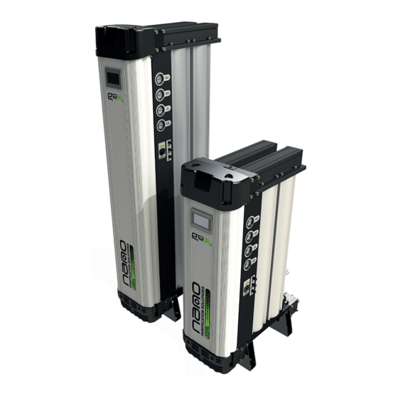
- Page 1 GEN2 NITROGEN GENERATOR USER GUIDE...
-
Page 2: Table Of Contents
Contents Page General information 1.1. Document introduction 1.2. Support and Manufacturers details 1.3. Warranty Guidelines General safety 2.1. Intended Use 2.2. Personnel 2.3. Safe Handling Product Description 3.1. Technical Specification Product Contents 4.1. Packaging 4.2. Unpackaging The Equipment Product Dimensions Equipment Overview System Layout 7.1. -
Page 3: General Information
This manual is copyrighted, all rights reserved. It may not, in whole or in part, be copied, photocopied, reproduced, translated, or reduced to any electronic medium or machine readable form without prior consent in writing from nano-purification solutions. It may not be distributed through the internet or computer bulletin board systems without prior consent from nano-purification solutions. -
Page 4: General Safety
General safety Intended use of the Product The generator is exclusively intended for the production of Nitrogen gas from compressed air, which is free from bulk water, oil and solid matter constituents. The product should be sited within a building (see section 7.1 Site selection). The generator must be operated only in accordance with the data on the rating label and in accordance with the contractual conditions. Any operations that do not comply with those stated on the product rating label will render the warranty void. -
Page 5: Product Description
Product Description The nitrogen generator operates on the Pressure Swing Adsorption (PSA) principle to produce a continuous stream of nitrogen gas from clean dry compressed air. Pairs of dual chamber extruded aluminium columns, filled with Carbon Molecular Sieve (CMS), are joined via an upper and lower manifold to produce a two bed system. Compressed air enters the bottom of the ‘online’ bed and flows up through the CMS. Oxygen is preferentially adsorbed by the CMS, allowing nitrogen to pass through. -
Page 6: Product Contents
Product Contents GEN2 Series Nitrogen Generator Documentation • 1 x User Guide • 1 x Declaration of Conformity Packaging • 1 x Generator support base and box cover Packaging All products are securely packaged in a specifically designed wooden packing box. The nitrogen generator will be held in a horizontal position by wooden struts used to secure the product to the box base. The box top cover can be removed by removing the screws and lifted off in multiple pieces. Damage to Packaging Check immediately to establish whether damage has occurred to the external packaging and if the damage extends to the product inside. If there is damage to a product, contact the relevant supplier immediately. -
Page 7: Unpackaging The Equipment
4.2 Unpacking the Equipment The generator is supplied in a wooden crate. It is recommended that the crate be moved into position using a forklift truck or pallet truck. Remove the generator from the wooden crate using an overhead crane. Use the following illustrations for correct guidance on safe handling and lifting techniques. -
Page 8: Product Dimensions
Product Dimensions 14.17 [360] 15.74 [400] INLET MODEL PORT SIZE Inches Inches Inches Inches Inches Inches Inches 1” GEN2-1110 22.95 8.42 47.83 1215 6.37 9.92 15.43 44.58 1132.5 GEN2-2110 1” 29.56 15.03 47.83 1215 6.37 9.92 15.43 44.58 1132.5 1” 36.18 21.65... -
Page 9: Equipment Overview
Equipment Overview (GEN2 1110, 2110, 3110, 2130, 3130, 4130, 6130, 8130, 10130, 12130) All connection points are clearly marked on the generator and are represented in the diagram below. Air Inlet HMI Screen Sample Point ‘Dimension F’ Display (1/8” Port) (1”... -
Page 10: System Layout
N2 Storage (Optional) (1 micron) (1) It is the customers responsibility to ensure pressure relief valves are fitted to the compressed air system. All vessels supplied by nano come with a pressure relief valves and pressure gauge as standard. (2) Buffer vessel is used for mixing nitrogen gas, this is not to be used as downdtream storage. -
Page 11: Site Location
Site Location When selecting an installation site for the generator , ensure the following conditions are met: • The site should be located indoors on a flat surface protected from weather and other harmful conditions. • The ambient temperature must not drop below 41°F (+5°C) or exceed 122°F (+50°C). • The installation site should be level and able to support the weight of the product. • Ensure sufficient space around the product, we recomend atleast 1m around the generator to allow access for operation and maintenance. •... -
Page 12: Electrical Control Panel
Electrical Control Panel Main Power Connection ‘RS’ Remote Start Cable Remote Start/Stop Alarm Outputs Main fig.1 Connections Electrical Power Requirements Supply: 88 - 264 VAC 47 -63 Hz Input Current: 1.3 / 0.8A (115/230 VAC) 2.0A Fuse 5 x 20 (Thermal) 250v Page 12 17-110 -0143... -
Page 13: Remote Alarms
Remote Alarms There are two seperate remote alarms for Pressure & Purity and a No volt / dryer control contact(see fig.1) A1 Terminal : input (0-24v DC). A1 Terminal : output (0-24v DC) common alarm output for pressure & purity. A2 Terminal : input (0-24v DC). A2 Terminal : output (0-24v DC) for dryer control only. Remote Stop/Start •... -
Page 14: Hmi Interface
HMI Screen Interface Menu Information Alarm Mute Charts Fault Log Set Time Login Service Record Service Contact User Engineer Distributor Settings Installation Service Reset Service Details Manual Overide Customer Alarm Mute The Alarm mute button will de-activate any active alarm (new alarms will activate independently). Once the current fault / Alarm has been rectified the mute function is re-set. - Page 15 There are three levels of pass-code protection, these are User, Engineer and Distributor. To access Level 1 (User) select the menu button on the home screen, then select the login button. From there select ‘User from the drop down menu and enter password ‘1234’. Settings (Level 1 Access - Pass-code ‘1234’) You are able to adjust the following: - Purity Alarm...
-
Page 16: Oxygen Analyzer Calibration
Oxygen Analyzer Calibration (GEN2 1110, 2110, 3110) Ballvalve Ballvalve ‘A’ ‘B’ Gas From Nitrogen External Sample/ Generator Calibration Gas 1. Close ball valve ‘A’ (this will stop gas flowing from the generator to the oxygen analyzer). 2. Allow the oxygen analyzer process arrangement to depressurize before introducing the calibration gas. 3. Once depressurized (this will be shown on the pressure gauge), connect your calibration gas to the sample point located on the enclosure (page 9). -
Page 17: Gen2 - 2130, 3130, 4130,6130, 8130, 10130, 12130
(GEN2 2130, 3130, 4130, 6130, 8130, 10130, 12130) External Sample/ Calibration Gas Gas From Nitrogen Generator Ballvalve Ballvalve ‘B’ ‘A’ 1. Close ball valve ‘A’ (this will stop gas flowing from the generator to the oxygen analyzer). 2. Allow the oxygen analyzer process arrangement to depressurize before introducing the calibration gas. 3. Once depressurized (this will be shown on the pressure gauge), connect your calibration gas to the sample point located on the enclosure (page 9). -
Page 18: Sensor Calibration
Sensor Calibration Procedure Press the Menu button ( Display should read E:1 Press the Enter button ( 250ml/m 7.25 psi (0.5 bar) Using the Next (increment) button ( ) and the Previous (decrement) button ( set the display to that of the calibration gas level. Press the Enter button ( ). -
Page 19: Maintenance
10. Maintenance Maintenance operations should only be carried out by authorized, competent and suitably trained personnel. • Maintenance operations only to be conducted when the system has been shut down, fully depressurized and isolated completely from the compressed gas and electrical supply. Beware a characteristic of the CMS could cause the vessel to repressurize slowly up to 2 barg. -
Page 20: Service Schedule
10.3 Service Schedule Recommended Service Intervals Service 12 Months 24 Months 36 Months 48 Months 60 Months 72 Months 84 Months 96 Months (or 8,000 (or 16,000 (or 24,000 (or 32,000 (or 40,000 (or 48,000 (or 56,000 (or 64,000 hours) hours) hours) hours) hours) -
Page 21: Troubleshooting
11. Troubleshooting Problem Problem Caused Solution 1. Insufficient inlet pressure 1. Adjust inlet pressure settings. (check rating plate). 2. Electrical Fault 2. Ensure the power is on and the generator display panel is illuminated; check the generator is cycling correctly. 3. Moist or contaminated CMS 3. Eliminate the cause of contamination. Check external inlet filtration (inc. Water separator) for failed auto-drains or Poor N2 purity or... -
Page 22: Warranty
12. Warranty All products are supplied with a 2 year manufacturer’s warranty from the date of purchase. The generator should be installed, operated and maintained in accordance with the manufacturer’s guidelines. Only genuine service parts should be used and no modifications made. For further information please contact your supplier. CMS is expected to operate for 10 years or more without issue when high purity air is supplied to it. The integral dryers have a similar life expectancy. Provided the inlet air quality is maintained, the CMS and AMT dryers are warranted for 2 year. Care must be taken with air supplied from an oil lubricated compressor to keep its operating temperature low to minimize oil vapor. -
Page 23: Electrical Schematic
14. Electrical Schematic 14.1. GEN2 1110, 2110, 3110, 2130, 3130, 4130, 6130, 8130, 10130, 12130 17-110-0143 Page 23... - Page 24 14.2. Notes : Electrical Schematic THIS DRAWING IS NOT AN ACCURATE VISUAL REPRESENTATION AND SHOULD BE USED ONLY FOR WIRING INSTRUCTIONS. FOR % ANALYSER (09-100-3047) USE CONECTIONS 1, 2 & 3. NEUTRAL (BLACK WIRE) TO TERMINAL 1. LIVE (RED WIRE) TO TERMINAL 5. EARTH (GREEN WIRE) TO TERMINAL 3. FOR PPM ANALYSER (09-100-3046) USE CONNECTIONS 3, 4 & 5.
-
Page 25: Process & Instrumentation Diagram
15. Process & Instrumentation diagram CMS Column CMS Column CMS Column CMS Column CMS Column CMS Column CMS Column CMS Column CMS Column CMS Column CMS Column CMS Column CMS Column CMS Column 17-110-0143 Page 25... - Page 26 Notes: ............................................................................................................................................................................................................................................................................................................................................................................................................................................Page 26 17-110 -0143...
- Page 27 Notes: ............................................................................................................................................................................................................................................................................................................................................................................................................................................17-110-0143 Page 27...
- Page 28 5509 David Cox Road Charlotte NC 28269 Telephone: (704) 897-2182 Fax: (704) 897-2183 Internet:www.n-psi.com E-mail:support@n-psi.com nano-purification solutions ltd. Dukesway Team Valley Trading Estate Gateshead NE11 0PZ United Kingdom Telephone: +44 (0) 191 497 7700 Fax: +44 (0) 191 497 7709 Internet: www.n-psi.co.uk E-mail: enquiries@n-psi.co.uk...
Need help?
Do you have a question about the GEN2-1110 and is the answer not in the manual?
Questions and answers