Table of Contents
Advertisement
Quick Links
Advertisement
Table of Contents

Subscribe to Our Youtube Channel
Related Manuals for NANO 3 N2 Series


Summary of Contents for NANO 3 N2 Series
- Page 1 NITROGEN GENERATOR SERIES 3 N² USER GUIDE:...
-
Page 2: Table Of Contents
Document Contents Title Page 1. General Information 1.1 Document Introduction 1.2 Support & Manufacturer’s Details 2. General Safety 3. Description of the Product 3.1 Technical Description 4. Product Contents 4.1 Packaging 4.2 Un-packing the equipment 5. Product Dimensions 6. -
Page 3: General Information
This manual is copyrighted, all rights reserved. It may not, in whole or in part, be copied, photocopied, reproduced, translated, or reduced to any electronic medium or machine readable form without prior consent in writing from nano-purification solutions. It may not be distributed through the internet or computer bulletin board systems without prior consent from nano-purification solutions. -
Page 4: General Safety
2. General safety For your own safety, when carrying out work on this product, all relevant national safety regulations must be complied with relating to pressurized and electrical systems. Intended use of the Product The generator is exclusively intended for the production of N2 from compressed air, which is free from bulk water, oil and solid matter constituents. -
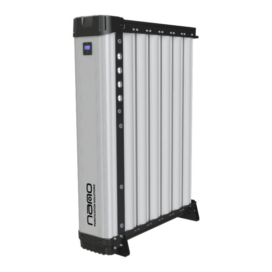
Page 5: Description Of The Product
3. Description of Product The n-psi nitrogen generator operates on the Pressure Swing Adsorption (PSA) principle to produce a continuous stream of nitrogen gas from clean dry compressed air. Pairs of dual chamber extruded aluminium columns, filled with Carbon Molecular Sieve (CMS), are joined via an upper and lower manifold to produce a two bed system. -
Page 6: Product Contents
4. Product Contents Series 3 N² Nitrogen Generator Documentation • 1 x User Guide • 1 x Declaration of Conformity Packaging • 1 x Generator support base and box cover • Care Should be taken and inspection undertaken during unpacking to ensure that the product is not damaged. -
Page 7: Packaging
4.1 Packaging All products are securely packaged in a bespoke wooden packing box. The generator will be held in a horizontal position by wooden struts; using straps to secure the product to the box base. The box top cover can be removed by removing the 4 fixing screws and lifting off in one piece. The support packing box permits longitudinal stacking;... -
Page 8: Unpacking The Equipment
4.2 Unpacking the Equipment The generator is supplied in a wooden crate. It is recommended that the crate be moved into position using a forklift truck or pallet truck. Remove the generator from the wooden crate using an overhead crane. Use the following illustrations for correct guidance on safe handling and lifting techniques. -
Page 9: Product Dimensions
5. Product Dimensions Front Side CONNECTION WEIGHT MODEL SIZE ins [mm] ins [mm] ins [mm] ins [mm] ins [mm] mm [ins] ins [mm] ins [mm] ins [mm] lbs [KG] NNG-2110 1/2” 26 [650] 15 [382] 47 [1210] 15.7 [400] 14.2 [360] 10 [262] 40 [1009] 242 [110]... -
Page 10: Equipment Overview
6. Equipment Overview All connection points are clearly marked on the generator and are represented in the diagram below. Ports 1-4 are factory set for customer requirement but can be changed internally. Air Inlet Port N² Outlet Port to buffer... -
Page 11: System Layout
7. System Layout Only personnel trained, qualified and approved by nano-purification solutions should perform installation, commissioning, service and repair procedures. With External Desiccant Dryer Description Description Buffer Vessel Compressor Pressure Relief Valve* Wet Air Receiver ² nano WS Generator (With Internal Dust Filtration) -
Page 12: Site Location
7.1 Site Location When selecting an installation site for the generator , ensure the following conditions are met: • Installation site should be located indoors on a flat surface protected from the weather and other harmful conditions. •... -
Page 13: Mechanical Installation
Once the generator has been located into position, install the ball valves and the pipework ready for connection to the buffer vessel and compressed air supply. nano M1 grade filter The diameter of the pipes must be sufficient to allow unrestricted inlet air supply to the generator and nitrogen supply to the applications shown in the table below. -
Page 14: Electrical Installation
7.3 Electrical Installation Mains Power Connection Supplied with 3 metres of cable: If the cable needs to be replaced: • Disconnect from mains supply. • Unscrew the 4 x M5 cap head screws in order to remove the generator top cover. -
Page 15: Generator Operation
8. Generator Operation Locate the electrical connector on the underside of the controller in the shroud. 8.1 6 Pin Electrical Connector Configuration Link 5/6 (-Ve/+Ve) 4-20mA Retransmission (Optional - where fitted) Links 2/3 General (no-volt) alarm output Links 1/4 Remote stop/start link Generator Remote Stop/Start Control (if required) •... -
Page 16: Pin Electrical Connector Configuration
General Alarm Output • Pins 2 & 3 on the electrical connector provide a zero volt alarm output for customer control panel indication. These pins are connected to relay contacts within the controller which will close when the service or O2 purity (optional) / pressure alarm conditions arise. -
Page 17: Start Up Procedure
8.2 Start-up Procedure • Ensure the Inlet Air Quality (ISO 8573.1:2010) is Class 1.2.1 or Class 1.5.1 when fitted with AMT integral dryer and the operating pressure is between 87-145psig (6 -10barg) • The inlet air temperature is between 34.7 – 104°F (1-40°C). Hours Run 00000 02 Purity... -
Page 18: Shut Down Procedure
8.3 Shut Down Procedure The generator can be shut down remotely (recommended) using remote wiring configuration see section 8, When the generator is shut down remotely, the shut down procedure will commence. The current cycle will be completed, then both exhaust valves will open for 2 minutes to exhaust the CMS bed. After which the exhausts will be closed, in effect sealing the generator ready for start up. -
Page 19: Oxygen Analyser Calibration
9. Oxygen Analyser Calibration Oxygen Analyser MENU Sensor Calibration ‘T’ Piece 1. Remove the 2x M5 cap head screws and remove the top cover. 2. Disengage the Front Shroud latches and open the door to reveal N process enclosure. 3. Identify O sensor assembly &... - Page 20 9.1 Sensor Calibration Procedure Press the Menu button ( Display should read E:1 Press the Enter button ( 250ml/m 7.25 psi (0.5 bar) Using the Next (increment) button ( and the Previous (decrement) button ( set the display to that of the calibration gas level.
-
Page 21: Maintenance
10. Maintenance Maintenance operations should only be carried out by authorized, competent and suitably trained personnel. • Maintenance operations only to be conducted when the system has been shut down, fully depressurized and isolated completely from the compressed gas and electrical supply. •... -
Page 22: Service Schedule
Service B: Control valve replacement Service C: O² sensor exchange (if fitted) Required service kits are dependant on nitrogen generator model and purity. Please contact Nano Purification Solutions to ensure the correct service kit is supplied 10.4 Calibration Sensor (where fitted) sensors must be calibrated every 3 months (See pages 19 &... -
Page 23: Troubleshooting
11. Troubleshooting Problem Problem Caused Solution 1. Insufficient inlet pressure 1. Adjust inlet pressure settings. (min operating inlet pressure 87psig / 6barg). 2. Electrical Fault 2. Ensure the power is on and the generator display panel is illuminated; check the generator is cycling correctly. 3. -
Page 24: Warranty
All products are supplied with a 5 year manufacturer’s warranty from the date of purchase. The generator should be installed, operated and maintained in accordance with the manufacturer’s guidelines. Only genuine service parts should be used and no modifications made. For further information please contact nano- purification solutions. -
Page 25: Service Record
13. Service Record Installation Date: Carried out by: GENERATOR SERVICE RECORD PRODUCT SERIAL NO. PRODUCT CODE: ............................HOURS SERVICED BY DATE NOTES SHOWN (PRINT/SIGN) 17-110-0142 Page 25... - Page 26 Notes: ............................................................................................................................................................................................................................................................................................................................................................................................................................................Page 26 17-110-0142...
- Page 27 Notes: ............................................................................................................................................................................................................................................................................................................................................................................................................................................17-110-0142 Page 27...
- Page 28 11330 Vanstory Drive Huntersville, NC 28078 Telephone: (704) 897-2182 Fax: (704) 897-2183 Internet:www.n-psi.com E-mail:support@n-psi.com...
Need help?
Do you have a question about the 3 N2 Series and is the answer not in the manual?
Questions and answers