Table of Contents
Advertisement
Advertisement
Table of Contents

Related Manuals for Harbor Breeze TALAMORE TAL60BNK8LR


Summary of Contents for Harbor Breeze TALAMORE TAL60BNK8LR
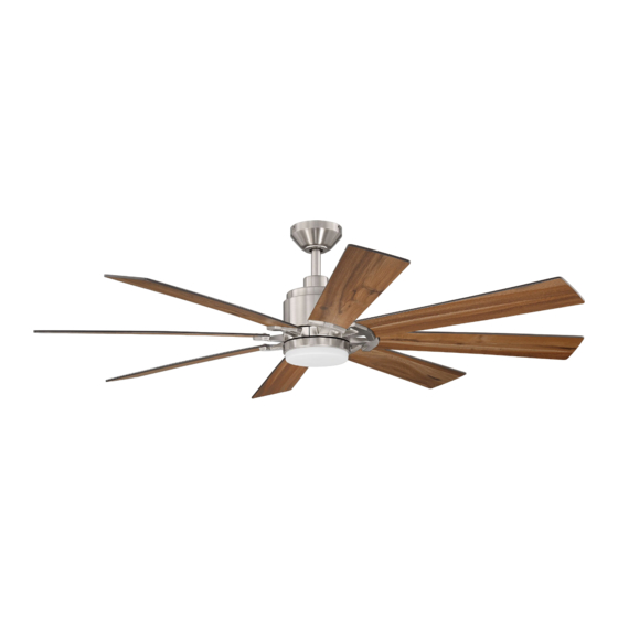
- Page 1 ITEM #5190468 TALAMORE CEILING FAN MODEL #TAL60BNK8LR Español p. 20 ATTACH YOUR RECEIPT HERE 4007498 Purchase Date Questions, problems, missing parts? Before returning to your retailer, call our customer service department at 1-800-527-1292, 8:30 a.m. - 5 p.m., CST, Monday - Friday.
-
Page 2: Table Of Contents
TABLE OF CONTENTS Safety Information ......................... 2 Package Contents ........................ 4 Hardware Contents ........................... 5 Preparation ........................... 5 Initial Installation ........................5 Downrod-Style Fan Mounting ....................7 Closemount-Style Fan Mounting ................... 9 Wiring ...........................11 Final Installation ........................12 Operating Instructions ......................16 Care and Maintenance ...................... - Page 3 SAFETY INFORMATION DANGER When using an existing outlet box, make sure the outlet box is securely attached to the building structure and can support the full weight of the fan. Failure to do this can result in serious injury or death.
-
Page 4: Package Contents
PACKAGE CONTENTS PART DESCRIPTION PART DESCRIPTION QUANTITY QUANTITY Downrod Motor Plate Screw (preassembled) Canopy Blade Arm Mounting Bracket Shade Motor Housing Pin (preassembled) Yoke Cover Clip (preassembled) LED Light Kit Canopy Cover Canopy Mounting Screw (preassembled) (preassembled) Remote Control Receiver Fitter Plate Remote Pack Fitter Plate Screw... -
Page 5: Hardware Contents
HARDWARE CONTENTS (shown actual size) Fiber Blade Screw Blade Wire Washer Connector Qty. 24 Qty. 24 + 1 extra Qty. 4 + 1 extra PREPARATION Before beginning assembly of product, make sure all parts are present. Place motor on carpet or on foam to avoid damage to finish. - Page 6 INITIAL INSTALLATION 2. Determine mounting method to use. A. Downrod mount (standard or angled ceiling). B. Closemount (standard ceiling only). 17° max. IMPORTANT: If using the angle mount, check to make sure the ceiling angle is not steeper than 17°. *Helpful Hint: Downrod-style mounting is best suited for ceilings 8 ft.
-
Page 7: Downrod-Style Fan Mounting
INITIAL INSTALLATION Remove motor screw/washers (S) from underside of motor housing (D) and save for blade arm attachment later on. [If there are plastic motor blocks installed with the motor screws/washers (S), discard the plastic motor blocks.] Motor For DOWNROD-STYLE FAN MOUNTING, Block proceed to step 1a below. - Page 8 INITIAL INSTALLATION Slip downrod (A) into yoke, align holes and re-install pin (N) and clip (O). Tighten set screw and nut. Slide yoke cover (E) down until it rests on top of motor housing (D). Set Screw and Nut Depending on the length of downrod you use, you may need to cut the lead wires back to simplify the wiring.
-
Page 9: Closemount-Style Fan Mounting
DOWNROD-STYLE FAN MOUNTING Install hanging ball of downrod (A) into opening of mounting bracket (C). Align slot in hanging ball with the tab in mounting bracket (C). DANGER: Failure to align slot in hanging ball with the tab in mounting bracket (C) may result in serious injury or death. - Page 10 CLOSEMOUNT-STYLE FAN MOUNTING Pull wires up through hole in the middle of the Screw canopy (B) and attach canopy (B) to motor housing (D) using the three previously removed Lock screws and lock washers. Washer Temporarily hang fan on the tab on the mounting bracket (C) using one of the non-slotted holes in the canopy (B).
-
Page 11: Wiring
WIRING WARNING: To reduce the risk of fire, electrical shock or personal injury, wire connectors provided with this fan are designed to accept only one 12-gauge house wire and two lead wires from the fan. If your house wire is larger than 12-gauge or there is more than one house wire to connect to the corresponding fan lead wires, consult an electrician for the proper size wire connectors to use. -
Page 12: Final Installation
WIRING Wrap electrical tape (not included) around each individual wire connector down to the wire. WARNING: Make sure no bare wire or wire strands are visible after making connections. Place Wire GREEN and WHITE connections on opposite side of Connector the outlet box from the BLACK and BLUE (if applicable) connections. - Page 13 FINAL INSTALLATION DANGER: To reduce the risk of serious bodily injury, DO NOT use power tools to assemble the blades (J). If screws are overtightened, blades (J) may crack and break. Partially insert three blade screws (AA) along with three fiber blade washers (BB) into holes in blade (J) to attach blade arm (L) to blade (J).
- Page 14 FINAL INSTALLATION 5. Partially loosen two fitter plate screws (I) on the underside of the fitter plate (H) and remove the other fitter plate screw (I). Molex Connections 6. Connect WHITE wire from LED light kit (F) to WHITE wire from motor housing (D). Connect BLUE wire from LED light kit (F) to BLUE (or BLACK) wire from motor housing (D).
- Page 15 FINAL INSTALLATION Align slots on shade (M) with protrusions on underside of fitter plate (H). Turn shade (M) clockwise until it no longer turns. NOTE: Pull down gently on the shade (M) to make sure it is secured completely. Protrusion Slot If you wish to use the remote control bracket from remote pack (R) on a wood surface, install...
-
Page 16: Operating Instructions
OPERATING INSTRUCTIONS CAUTION: The remote control transmitter can be programmed to multiple receivers or fans. If this is not desired, turn wall switch off to any other programmable receiver or fan. FCC Compliance Notice for Remote Control and LED Light Kit CAUTION: Changes or modifications not approved by the party responsible for compliance could void the user's authority to operate the equipment. -
Page 17: Care And Maintenance
OPERATING INSTRUCTIONS Operation buttons on the panel of the remote control transmitter: - Reverse function (fan must be set on low before reversing blade direction). - Fan speeds: 1 (lowest) to 6 (highest) - To turn fan ON or OFF - Timer: Fan stops after 1 hour/4 hours/8 hours COLOR - To turn light ON or OFF... -
Page 18: Troubleshooting
TROUBLESHOOTING WARNING: Before beginning work, shut off the power supply to avoid electrical shock. PROBLEM POSSIBLE CAUSE CORRECTIVE ACTION Fan does not move. 1. Power is off or fuse is blown. 1. Turn power on or check fuse. 2. Faulty wire connection. 2. -
Page 19: Limited Lifetime Warranty
LIMITED LIFETIME WARRANTY The distributor warrants this fan to be free from defects in workmanship and materials present at time of shipment from the factory for Lifetime limited from the date of purchase. This warranty applies only to the original purchaser. The distributor agrees to correct any defect at no charge or, at our option, replace the ceiling fan with a comparable or superior model.
Need help?
Do you have a question about the TALAMORE TAL60BNK8LR and is the answer not in the manual?
Questions and answers