Table of Contents
Advertisement
Quick Links
Advertisement
Table of Contents

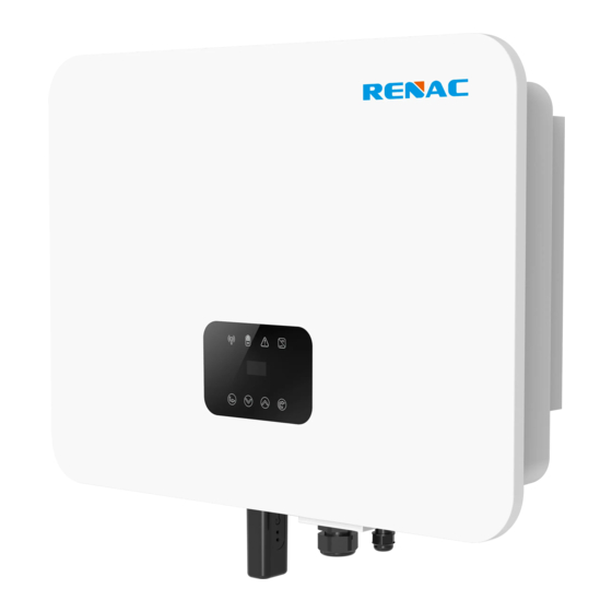
Summary of Contents for Renac N1-HV Series
- Page 1 N1-HV Series User Manual N1-HV-3.0 N1-HV-3.68 N1-HV-5.0 N1-HV-6.0...
-
Page 2: Table Of Contents
Content 1. About This Manual 1.1 Applicability 1.2 Target group 1.3 Symbols used 2. Safety 2.1 General Safety 2.2 Important safety instructions 2.3 Explanation of symbols 3. Introduction 3.1 Basic features 3.2 Work modes 3.3 Terminals 3.4 Dimension 4. Technical data 5. -
Page 3: About This Manual
N1-HV-3.0 N1-HV-3.68 N1-HV-5.0 N1-HV-6.0 corporation or individual should not plagiarize, partially copy or fully copy it, and no reproduction or distribution of it in any form or by any means without prior written permission from RENAC Power. 1.2 Target group... -
Page 4: Explanation Of Symbols
◆Do not open inverter cover or change any components without RENAC The N1-HV series hybrid inverters apply to PV energy storage system with PV module, battery, loads and grid. NOTICE The energy produced by PV system shall be used to optimize self-consumption, excess power charge battery and the rest power could inverter will be invalid. -
Page 5: Work Modes
N1-HV Series N1-HV Series User Manual User Manual 3.2 Work modes Work mode: Force time use Work mode: Self-use into the grid. Work mode: Feed in Pirority This mode applies the area that has high feed-in tariff and export control. -
Page 6: Terminals
3.3 Terminals The N1-HV series hybrid inverters apply to PV energy storage system with PV module, battery, loads and grid. The energy produced by PV system shall be used to optimize self-consumption, excesspower charge battery and the rest power could... -
Page 7: Installation
N1-HV Series N1-HV Series User Manual User Manual Model Model AC Output Data(on-grid) Residual Current Monitoring Intergrated 3000 3680 5000* 6000 Over-heat Protection Intergrated 3000 3680 5000* 6000 AC Overcurrent Protection Intergrated 21.7* 26.1 AC Short-circuit Protection Intergrated 21.7* 26.1... -
Page 8: Check For Transport Damage
N1-HV Series N1-HV Series User Manual User Manual 5.2 Check for transport damage 5.3 Installation precaution ・ ・ ・Do not install the inverter in potentially explosive areas. ・ cause corrosion and damage to the electric components. ・Provide adequate ventilation when using batteries, and also read the warning label on the bottom of the inverter. -
Page 9: Preparation
N1-HV Series N1-HV Series User Manual User Manual 5.5 Preparation ・ Tool Model Function ・ ・Avoid sudden movements and jolts when unloading and positioning the unit. Internal handling procedures must be conducted with care. Do not exert leverage on the components of the machine. -
Page 10: Electrical Wiring Connection
N1-HV Series N1-HV Series User Manual User Manual 5.7 Electrical Wiring Connection ・PV string connection ・AC output connection ・Battery connection System Connection Diagrams ・Battery power connection , ・Battery communication connection ・EPS connection ・Earth connection PV Panels ・Communication connection 5.7.1 PV Wiring Connection ・... - Page 11 N1-HV Series N1-HV Series User Manual User Manual 6.Push the insert into the sleeve (□ 7.Tight the DC connector. 7.Tighten the cable gland to 2 Nm (□ to hold the connector in place. b.Rotate the cable nut to secure the cable.
- Page 12 N1-HV Series N1-HV Series User Manual User Manual 2. Lead the AC cable through the cable gland and the housing. Overview for all battery connections BAT+ BAT- 5.7.3AC Output Connection required, a type A RCD with rated residual current of 30mA or higher is recommended.
- Page 13 N1-HV Series N1-HV Series User Manual User Manual 5.7.5 Communication connection Meter wiring diagram Communication interface (optional), Dry contact and extend port and for human and machine communication, etc., can be delivered to PC or other monitoring equipment via these interfaces.
-
Page 14: Inverter Manipulation
N1-HV Series N1-HV Series User Manual User Manual 5.8 Inverter manipulation Name Object ・ Indicator ・ ・ ・ ・Turn on the external AC, DC switch. ・ Button ・ Start inverter: LCD Screen Display the information of the inverter. ・Inverter will start automatically when the PV panel generate enough energy or the battery is charged. -
Page 15: Lcd Operation
N1-HV Series N1-HV Series User Manual User Manual A) Solar ====On-Grid==== ====Safety==== ==Volt Protect== >Safety >AS4777 >Vac Upper Slow Grid 260.0V ==Volt Protect== Export Control >Vac Lower Slow This status shows the real time PV parameters of the system. The input voltage, current and power of each PV input. Press up 180.0V... - Page 16 N1-HV Series N1-HV Series User Manual User Manual 3. History D) PV Connection ====History==== ===Yield Logs=== ===Yield Logs=== ===Yield Logs=== =====Settings===== =PV Connection= =PV Connection= >Yield Logs >Output Total >Input Total >Batchr Total Data&Time Error Logs >Multi >Comm =====Menu===== Work Mode Status >PV Config...
- Page 17 N1-HV Series N1-HV Series User Manual User Manual J) Feature ==Volt Protect== >Vac Upper Slow ==Volt Protect== 260.0V >Vac Lower Slow 180.0V ====On-Grid==== ==Volt Protect== ====Feature==== =Remote Control= ===Advanced*=== =====Grid===== Safety >Vac Upper Fast >Remote Control >Disable On-Grid >Volt Protect ==Volt Protect== >Grid...
-
Page 18: Troubleshooting
N1-HV Series N1-HV Series User Manual User Manual Inverter over current or battery over current or PV over current detected by hardware. M) USB • Disconnect PV, grid and battery, then reconnect. ====Upgrade==== ==DSPM Upgrade== ===Advanced*=== =====USB===== ====Upgrade==== ==DSPS Upgrade== >DSPM Upgrade... - Page 19 N1-HV Series N1-HV Series User Manual User Manual The sample value between master and slave is not consistent. The manager eeprom is fault. • Disconnect PV, grid and battery, then reconnect. • Disconnect PV, grid and battery, then reconnect. Over load in off grid mode.
-
Page 20: Decommissioning
・Are the display panel and the communications cable properly connected and undamaged? Contact Renac Power Customer Service for further assistance. Please be prepared to describe details of your system installation and provide the model and serial number of the unit.


Need help?
Do you have a question about the N1-HV Series and is the answer not in the manual?
Questions and answers