Hausted Horizon Series Operating Manual
X-ray trauma stretcher
Hide thumbs
Also See for Horizon Series:
- Operating manual (24 pages) ,
- Operating manual (32 pages) ,
- Operating manual (53 pages)

Related Manuals for Hausted Horizon Series


Summary of Contents for Hausted Horizon Series
- Page 1 Operating Manual Hausted Horizon Series ® X-ray trauma Stretcher Model: 468Xry V1 01.11 076204 HauSteD® patient HanDling SySteMS, llC...
- Page 2 WARNING - COPYING PROHIBITED this manual is protected by Federal Copyright law, which provides for damages of up to uSD $20000, as well as criminal fines and imprisonment, for unauthorized copying.
- Page 3 Hausted® Horizon Series at peak capability and to help avoid untimely or costly X-ray trauma Stretcher. all personnel involved in the interruptions.
- Page 4 EC Authorized Representative Cepartner4u BV eSDOOrnlaan 13 3951DB Maarn the netherlands +31(0)6 516 536 26 Manufactured by: Hausted® patient Handling Systems, llC 2511 Midpark road Montgomery, al 36109 334.215.5151 Main 877.706.5151 toll Free 334.215.5150 Fax www.Hausted.com equipment not suitable for use in the presence of a flammable anesthetic mixture with air or oxygen or nitrous oxide.
-
Page 5: Table Of Contents
taBle OF COntentS 1 listing of warnings and Cautions ........................ 2 uncrating instructions ............................3 Operating instructions ............................3.1 Stretcher Features ................................3-1 3.2 Stretcher Specifications .............................3-3 3.3 Braking and Steering Operation ..........................3-4 3.3.1 applying the Brakes ..............................3-4 3.3.2 releasing the Brakes ...............................3-4 3.3.3 applying the Steering lock/Fifth wheel ......................3-4 3.3.4 releasing the Steering lock/Fifth wheel ......................3-4 3.4 litter top Height adjustment ...........................3-5... - Page 6 taBle OF COntentS 3.10 loading the Built-in grid Holder ........................3-14 3.11 loading Cassettes laterally ..........................3-15 3.11.1 lower the retracto rails on stretcher ......................3-15 3.12 using Carrier Offset positions ..........................3-16 3.12.1 end label Markings ............................3-16 3.12.2 placing Carrier in Offset position ........................3-16 4 troubleshooting guide ............................
-
Page 8: Listing Of Warnings And Cautions
OF warningS anD CautiOnS the following Safety precautions must be observed Be sure rail is locked before leaving patient. when operating or servicing this Hausted® Horizon® Do not sit on end – tipping may ocur. Model 468Xry–X-ray and trauma Stretcher. -
Page 10: Uncrating Instructions
- leave carton intact. leave the equipment in the receiving your Hausted equipment has been carefully packed area until inspection is complete. at our manufacturing plant to ensure safe shipment CautiOn - pOSSiBle eQuipMent to your medical facility. -
Page 12: Operating Instructions
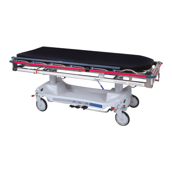
Operating inStruCtiOnS 3.1 StretCHer FeatureS Built-in Chest X-ray Cassette three-position patient Side rails positioning System See warnings C & D 3" pad Standard pneumatic Fowler Backrest radiolucent litter top Built-in i.V. and accessory patient Surface wells on all Four Corners Full perimeter protective Bumper... - Page 13 Operating inStruCtiOnS 3.1 StretCHer FeatureS warningS– CautiOnS anD prOper OperatiOn: Do not sit on end – tipping may occur. a. the stretchers have a warning label located at the foot end stating: maximum patient- weight 226 Kilograms (500 lbs.) B. patient entry, egress and transfer should always be done with the brakes locked.
-
Page 14: Stretcher Specifications
Maximum patient weight 226 Kilograms (500 lbs) Between rails 28.50 nOte: all dimensions are specified in inches. all dimension are ±.375 inches. patient Surface Hausted reserves the right to change specifications without notice. Stretcher weight: 315 lbs. 64.00 rail length 3.00 pad Standard 0-90°... -
Page 15: Braking And Steering Operation
Operating inStruCtiOnS 3.3 BreaKing anD Steering OperatiOn 3.3.1 applying the Brakes the four-wheel central braking system is activated by depressing the red pedal at any of the four corners of the unit (Figure 3-1). to fully engage the brakes, the pedal should be pressed approximately 45°. -
Page 16: Litter Top Height Adjustment
Operating inStruCtiOnS 3.4 litter tOp HeigHt aDJuStMent 3.4.1 Height adjustment press the pump pedal to the floor (Figure 3-4), then release. repeat this process until the desired height is obtained. use smooth strokes on pump pedal to ensure patient comfort. Figure 3 - 4 3.4.2 lowering the litter top press down on the two release pedals at... -
Page 17: Retracto Rail Operation
Operating inStruCtiOnS 3.5 retraCtO rail OperatiOn CautiOn: always be sure rail is locked in the full and upright position before leaving the patient unattended. 3.5.1 raising the rail Figure 3 - 8 grasp the rail top cap in the middle of the rail (Figure 3-8) and lift. -
Page 18: Fowler Backrest Operation
Operating inStruCtiOnS 3.6 FOwler BaCKreSt OperatiOn 3.6.1 raising the Backrest grasp the fowler backrest tube and the gas spring activating handle (Figure 3-10), squeeze the handle and the tube together and lift. Once the desired incline is achieved, release the handle. (amount of manual lifting required Figure 3 - 10 will vary depending on patient size;... -
Page 19: Chest X-Ray Cassette System Operation
Operating inStruCtiOnS 3.7 CHeSt X - ray CaSSette SySteM OperatiOn 3.7.1 loading Cassettes raise the fowler to 90°. rotate the red angles out until they are 90° to the tube (Figures 3-12 & 3-13). insert the cassette between fowler angles (Figure 3-14). Support the cassette while rotating the pressure rods out (Figure 3-15), until they are pressing on the cassette Figure 3 - 12... -
Page 20: Loading The Cassette Carrier
Operating inStruCtiOnS 3.8 lOaDing tHe CaSSette Carrier nOte: the following instructions can be done from either side of the unit. 3.8.1 placing Carrier in loading position Before attempting to access the carrier, you must first place it in the proper position for loading. -
Page 21: Loading And Centering Cassette In Carrier
Operating inStruCtiOnS 3.8 lOaDing tHe CaSSette Carrier 3.8.3 loading and Centering Cassette in Carrier with the tray exposed, place the cassette between the two angles built into the carrier (Figure 3-26). Once the cassette is in the tray, push the angle up against the side of the Figure 3 - 26 cassette (Figure 3-27). -
Page 22: Positioning The Cassette Carrier
Operating inStruCtiOnS 3.9 pOSitiOning tHe CaSSette Carrier 3.9.1 proper usage of Side label Markings running along both sides of the stretcher on the lower tubes is a label that is used to assist in defining accurate location of the center point of the cassette along the longitudinal axis of the stretcher. the upper set of (green) numbers define the approximate center point that the X-ray will be taken on the stretcher (Figure 3-30). - Page 23 Operating inStruCtiOnS 3.9 pOSitiOning tHe CaSSette Carrier Figure 3 - 32 Figure 3 - 33 Figure 3 - 34 Simulated Center of X-ray Figure 3 - 35 3-12 076204...
-
Page 24: Adjust The Carrier Location
Operating inStruCtiOnS 3.9 pOSitiOning tHe CaSSette Carrier 3.9.2 adjust the Carrier location Determine the required location of the cassette carrier (See “proper usage of Side label Markings” on Section 3.9.1). grasp the red handle (Figure 3-36) and rotate it slightly toward the head end of the stretcher (Figure Figure 3 - 36 3-37). -
Page 25: Loading The Built-In Grid Holder
Operating inStruCtiOnS 3.10 lOaDing tHe Built - in griD HOlDer 3.10.1 loading the Built-in grid Holder position the carrier all the way toward the head end (see “adjusting the Carrier loca- tion,” above). raise the fowler backrest to an upright position (Figure 3-41), exposing the carrier. - Page 26 Operating inStruCtiOnS 3.11 lOaDing CaSSette laterally 3.11.1 adjust the Carrier location Slide one corner of the cassette between the gray rail cap and the pad (Figure 3-44). Continue inserting cassette until it is securely captured between rail and pad (Figure 3-45). Once in place the cassette can be slid up Figure 3 - 44 and down the length of the top as required...
-
Page 27: Using Carrier Offset Positions
Operating inStruCtiOnS 3.12 uSing Carrier OFFSet pOSitiOnS 3.12.1 end label Markings On both ends of the stretcher, on the lower tube, there is a label that will be used in defining the different “offset” positions that the carrier can be set to. in figure 3-47, the foot end of the stretcher is shown, as well as the positions. -
Page 28: Troubleshooting Guide
Once tightened, the pivot point will require lubrication (see “lubrication guide,” Section 5.2). Step 2. if the angles or rods still do not stay up: call Hausted for service. Step 1. replace labels and caps as required (see “replacement parts,”... - Page 29 Step 1. there are no customer serviceable items-contact Hausted for service. operate properly. Step 1. there are no customer serviceable items-contact Hausted for service. the hydraulic system does not oper- ate properly.
-
Page 30: Recommended Preventive Maintenance
reCOMMenDeD preVentiVe MaintenanCe procedure Schedule Material lubricate all moving and sliding 3 Months lubricating oil, light-duty grease, parts and hinge points wax stick lubricant (See "lubrication guide" in Section 5-3). neVer luBriCate gaS Spring, anD MeCH-lOCK SHaFtS inspect all fasteners to ensure 3 Months proper size wrench and screwdriver. -
Page 31: Recommended Cleaning Instructions
(see "lubrication guide" on page 5-3) nOte: Steam cleaning and pressure washing of stretcher is not recommended and can void warranty. For more detailed information, please contact: Hausted patient Handling Systems at 877.706.5151 076204... -
Page 32: Lubrication Guide
reCOMMenDeD preVentiVe MaintenanCe 5.2 luBriCatiOn guiDe piVOt pOintS On CHeSt piVOt pOintS On Centering CaSSette angleS anD angle linKS – unDer tray preSSure rODS (Only One SHOwn) piVOt pOintS On FOwler nO luBriCatiOn iS aCtiVating HanDle anD neeDeD On tHe BlaCK gaS Sping MOunting plaStiC BarS pOint (BOtH SiDeS) -
Page 34: Recommended Optional Accessories
Bumpers and pin Striping for Department identification 131936-00 plum Bumpers and pin Striping for Department identification it is recommended that only Hausted approved accessories be used with this device. to order accessories, or for more detailed information on accessories, please contact Hausted at: 1.877.706.5151 076204... - Page 36 reCOMMenDeD replaCeMent partS Figure 4 - 1 grid Holder Cassette Carrier uSe StanDarD pVC CeMent tO inStall nOte: use instant adhesive when installing any vinyl or rubber cap. use pVC cement to install item 20. Figure 4 - 1 076204...
- Page 37 reCOMMenDeD replaCeMent partS Figure 7 - 1. BaSe aSSeMBly item no. part no. C Description units per assembly 066508 aSSeMBly, Brake pedal, right 066507 aSSeMBly, Brake pedal, left 066544 Cap, Brake pedal, green 066543 Cap, Brake pedal, red 069459 riVet, Brake pedal Cap 068343 paD, pump pedal 061164...
- Page 38 reCOMMenDeD replaCeMent partS Figure 4 - 2 Figure 4 - 2 076204...
- Page 39 reCOMMenDeD replaCeMent partS Figure 4 - 2 item no. part no. C Description units per assembly 076295 laBel, left Side X-ray unit 076296 laBel, right Side X-ray unit 076298 laBel, Foot end X-ray 076297 laBel, Head end X-ray 076306 laBel, Head end Bumper 076307 laBel, Foot end Bumper 076303...
- Page 40 reCOMMenDeD replaCeMent partS Figure 4 - 3 For Service Call 877.706.5151 Figure 4 - 3 076204...
-
Page 41: Recommended Replacement Parts
reCOMMenDeD replaCeMent partS Figure 4 - 3 item no. part no. C Description units per assembly 075840 laBel, trauma Care, right 075831 laBel, Base end 075841 laBel, trauma Care, left 031457 laBel, universal Serial number 063022 laBel, Service 031458 laBel, Overlay, Clear Vinyl 076204... - Page 42 — provided such equipment has been properly installed and maintained and has not been misused and abused. the determination of proper installation, maintenance and use shall rest solely with Hausted. exempt five year...
- Page 44 Hausted offers annual maintenance agreements to give your capital equipment planned maintenance agreements that will help correct little problems before they become big ones. Hausted engineering Service combines the precise maintenance program and factory-trained technicians to assure you of maximum productivity.
Need help?
Do you have a question about the Horizon Series and is the answer not in the manual?
Questions and answers