Hausted Horizon Series Operating Manual
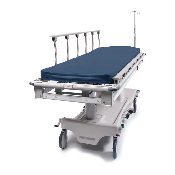
X ray trauma stretcher
Hide thumbs
Also See for Horizon Series:
- Operating manual (24 pages) ,
- Operating manual (53 pages) ,
- Operating manual (44 pages)

Related Manuals for Hausted Horizon Series


Summary of Contents for Hausted Horizon Series
- Page 1 OPERATING MANUAL Hausted Horizon Series Model 468XRY – X Ray Trauma Stretcher (08/30/06) 076204...
- Page 2 This manual contains important information on proper use and maintenance of the Hausted ® Horizon Series Model 468XRY – X-Ray Trauma Stretcher. All personnel involved in the use and maintenance of this equipment must carefully review and comply with the warnings, cautions and instruc- tions contained in this manual.
- Page 3 EC Authorized Representative STERIS Limited STERIS House Jays Close Viables Basingstoke Hampshire RG22 4AX UNITED KINGDOM Manufactured by: STERIS Corporation 2720 Gunter Park East Montgomery, AL 36109 • USA www.steris.com TEL: 334 277 6660 FAX: 334 271 5450 Equipment not suitable for use in the presence of a flammable anesthetic mixture with air or oxygen or nitrous oxide.
-
Page 4: Table Of Contents
TABLE OF CONTENTS Section Title Page 1 LISTING OF WARNINGS AND CAUTIONS ........1-1 1.1 Features ........................1-2 1.2 Stretcher Specifications ....................1-3 2 UNPACKING INSTRUCTIONS ............2-1 3 OPERATING INSTRUCTIONS ............3-1 3.1 Stretcher Features ....................... 3-1 3.2 Stretcher Specifications ....................3-2 3.3 Braking and Steering Operation .................. - Page 5 Section Title Page 5 RECOMMENDED PREVENTIVE MAINTENANCE ......5-1 5.1 Recommended Cleaning Instructions ................. 5-1 5.2 Lubrication Guide ......................5-2 6 OPTIONAL ACCESSORIES ............... 6-1 7 RECOMMENDED REPLACEMENT PARTS ........7-1 076204 Operator Manual Table of Contents...
-
Page 6: Listing Of Warnings And Cautions
LISTING OF WARNINGS AND CAUTIONS The following Safety Precautions must be observed when operating or servicing this Hausted ® Horizon ® Model 468XRY – X-Ray and Trauma Stretcher. WARNING indicates the potential for personal injury and CAUTION indicates the potential for damage to equipment. - Page 7 Your Hausted ® Horizon Series Model 468XRY – X-Ray Trauma Stretcher has been carefully packaged at our manufacturing plant to ensure safe shipment to you medical facility. There are several procedures you must follow to put your new stretcher into service.
-
Page 8: Features
OPERATING INSTRUCTIONS WARNING – PERSONAL IN- 3.1 Stretcher JURY HAZARD: Features A– The stretchers have a warning C– The brakes should always be label located at the foot end on and patient side rails up stating: maximum patient when the patient is not in weight 226 Kilograms (500 lbs.) trasnport. -
Page 9: Stretcher Specifications
NOTE: All dimensions are specified in inches. All dimensions are ±.375". 3.2 Stretcher STERIS reserves the right to change specifications without notice. Specifications 33.50 W A R N I N G – P E R S O N A L Overall Width INJURY: The stretchers have 29.00... -
Page 10: Braking And Steering Operation
3.3 Braking and Steering Operation The four-wheel central braking system is activated by depressing the red 3.3.1 Applying the Brakes pedal at any of the four corners of the unit (Figure 3-1). To fully engage the brakes, the pedal should be pressed approximately 45°. All four caster wheels should be locked from swiveling and rotating. -
Page 11: Lowering The Litter Top
3.3.4 Releasing the Depress the red pedal at any of the four corners of the unit, until the pedal is Steering Lock/Fifth Wheel in a horizontal position (Figure 3-2). All four wheels should rotate and swivel freely, and/or the optional fifth wheel will lift off the floor. 3.4 Litter Top Height Adjustment 3.4.1 Height Adjustment... -
Page 12: Reverse Trendelenburg Adjustment
3.4.4 Reverse Place the unit at maximum height; see “Height Adjustment.” Press down on the Trendelenburg Adjustment release pedal nearest the foot end (Figure 3-7), until desired position is obtained, then remove pressure. NOTE: Do not stand on release pedals. Figure 3-7 3.5 Retracto Rail Operation... -
Page 13: Fowler Backrest Operation
3.6 Fowler Backrest Operation Grasp the fowler backrest tube and the gas spring activating handle (Figure 3.6.1 Raising the Backrest 3-10), squeeze the handle and the tube together and lift. Once the desired incline is achieved, release the handle. (Amount of manual lifting required will vary depending on patient size;... - Page 14 Figure 3-12 Figure 3-13 Figure 3-14 Figure 3-15 Figure 3-16 Figure 3-17 Figure 3-18 Figure 3-19 Figure 3-20 Operating Instructions Operator Manual 076204...
-
Page 15: Loading The Cassette Carrier
NOTE: The following instructions can be done from either side of the unit. 3.8 Loading the Before attempting to access the carrier, you must first place it in the proper Cassette Carrier position for loading. Grasp the red handle (Figure 3-21) and rotate it slightly toward the head end of the stretcher (Figure 3-22). - Page 16 With the tray exposed, place the cassette between the two angles built into the 3.8.3 Loading and carrier (Figure 3-26). Once the cassette is in the tray, push the angle up against Centering Cassette in the side of the cassette (Figure 3-27). This automatically centers the cassette Carrier in the carrier.
-
Page 17: Positioning The Cassette Carrier
3.9 Positioning the Cassette Carrier 3.9.1 Proper Usage of Side Running along both sides of the stretcher on the lower tubes is a label that is Label Markings used to assist in defining accurate location of the center point of the cassette along the longitudinal axis of the stretcher. - Page 18 Figure 3-32 Figure 3-33 Figure 3-34 Simulated Center of X-Ray Figure 3-35 3-11 Operating Instructions Operator Manual 076204...
-
Page 19: Adjust The Carrier Location
3.9.2 Adjust the Carrier Determine the required location of the cassette carrier (See “Proper Usage of Location Side Label Markings” on Section 3.9.1). Grasp the red handle (Figure 3-36) and rotate it slightly toward the head end of the stretcher (Figure 3-37). This process de-activates the built-in brake. -
Page 20: Loading The Built-In Grid Holder
Position the carrier all the way toward the head end (see “Adjusting The Carrier 3.10 Loading the Location,” above). Raise the fowler backrest to an upright position (Figure 3- 41), exposing the carrier. Carefully place one end of the grid into the angle Built-In Grid Holder mounted to the carrier (Figure 3-42). -
Page 21: Using Carrier Offset Positions
On both ends of the stretcher, on the lower tube, there is a label that will be used 3.12 Using Carrier in defining the different “offset” positions that the carrier can be set to. In figure 3-47, the foot end of the stretcher is shown, as well as the positions. Position Offset Positions “A”... -
Page 22: Troubleshooting Guide
TROUBLESHOOTING GUIDE The following is a list of recommended inspections and customer serviceable items to perform, prior to calling STERIS service. Step 1. Make sure carrier is in proper position for loading or using offset positions (see “Loading Carrier will not pull out when pulling on black Cassette Carrier,”... -
Page 23: Recommended Preventive Maintenance
RECOMMENDED PREVENTIVE MAINTENANCE Material Procedure Schedule Lubricating oil, light-duty Lubricate all moving and sliding parts 3 Months grease, wax stick lubricant and hinge points (see “Lubrication Guide” (see “Lubrication Guide” in Sec- in Section 5-2). tion 5-2). 1 2 3 4 5 6 7 8 9 0 1 2 3 4 5 6 7 8 9 0 1 2 3 4 5 6 7 8 9 0 1 2 1 2 3 4 5 6 7 8 9 0 1 2 3 4 5 6 7 8 9 0 1 2 3 4 5 6 7 8 9 0 1 2 1 2 3 4 5 6 7 8 9 0 1 2 3 4 5 6 7 8 9 0 1 2 3 4 5 6 7 8 9 0 1 2 1 2 3 4 5 6 7 8 9 0 1 2 3 4 5 6 7 8 9 0 1 2 3 4 5 6 7 8 9 0 1 2 1 2 3 4 5 6 7 8 1 2 3 4 5 6 7 8 9 0 1 2 3 4 5 6 7 8 9 0 1 2 3 4 5 6 7 8 9 0 1 2 1 2 3 4 5 6 7 8 9 0 1 2 3 4 5 6 7 8 9 0 1 2 3 4 5 6 7 8 9 0 1 2 1 2 3 4 5 6 7 8 9 0 1 2 3 4 5 6 7 8 9 0 1 2 3 4 5 6 7 8 9 0 1 2 1 2 3 4 5 6 7 8 9 0 1 2 3 4 5 6 7 8 9 0 1 2 3 4 5 6 7 8 9 0 1 2 1 2 3 4 5 6 7 8 1 2 3 4 5 6 7 8 9 0 1 2 3 4 5 6 7 8 9 0 1 2 3 4 5 6 7 8 9 0 1 2 1 2 3 4 5 6 7 8 9 0 1 2 3 4 5 6 7 8 9 0 1 2 3 4 5 6 7 8 9 0 1 2 1 2 3 4 5 6 7 8 9 0 1 2 3 4 5 6 7 8 9 0 1 2 3 4 5 6 7 8 9 0 1 2 1 2 3 4 5 6 7 8 9 0 1 2 3 4 5 6 7 8 9 0 1 2 3 4 5 6 7 8 9 0 1 2 1 2 3 4 5 6 7 8 1 2 3 4 5 6 7 8 9 0 1 2 3 4 5 6 7 8 9 0 1 2 3 4 5 6 7 8 9 0 1 2 1 2 3 4 5 6 7 8 9 0 1 2 3 4 5 6 7 8 9 0 1 2 3 4 5 6 7 8 9 0 1 2 1 2 3 4 5 6 7 8 9 0 1 2 3 4 5 6 7 8 9 0 1 2 3 4 5 6 7 8 9 0 1 2 1 2 3 4 5 6 7 8 9 0 1 2 3 4 5 6 7 8 9 0 1 2 3 4 5 6 7 8 9 0 1 2 1 2 3 4 5 6 7 8... -
Page 24: Lubrication Guide
5.2 Lubrication Guide PIVOT POINTS ON CHEST PIVOT POINTS ON CENTERING CASSETTE ANGLES AND ANGLE LINKS – UNDER TRAY PRESSURE RODS (ONLY ONE SHOWN) PIVOT POINTS ON FOWLER NO LUBRICATION IS ACTIVATING HANDLE AND NEEDED ON THE BLACK GAS SPING MOUNTING PLASTIC BARS POINT (BOTH SIDES) FOWLER AND GAS... -
Page 25: Optional Accessories
OPTIONAL ACCESSORIES IV Poles 000E17-00 Stainless Steel 42" Long Fixed-height I.V. Rod 000018-00 Stainless Steel 27" to 54" long telescoping I.V. Rod 128770-00 000018 Telescoping I.V. Rod with Cable Attachment 126740-00 Infusion Pump IV Rod 1-1/8" Dia - 42" Long - Removable 065897-00 Mobile IV Stand Attachment Pads and Mattresses 067178-60 Pressurecare-4"... -
Page 26: Recommended Replacement Parts
RECOMMENDED REPLACEMENT PARTS Recommended Replacement Parts Operator Manual 076204... - Page 27 Grid Holder Cassette Carrier USE STANDARD PVC CEMENT TO INSTALL NOTE: Use instant adhesive when installing any vinyl or rubber cap. Use PVC cement to install Item 20. Figure 4-1. 076204 Operator Manual Recommended Replacement Parts...
- Page 28 FIG. & UNITS PER PART ITEM DESCRIPTION ASSEMBLY NUMBER 4-1- 066508 ASSEMBLY, Brake Pedal, Right ..........066507 ASSEMBLY, Brake Pedal, Left ............ 066544 CAP, Brake Pedal, Green ............066543 CAP, Brake Pedal, Red ............... 069459 RIVET, Brake Pedal Cap ............. 068343 PAD, Pump Pedal ................
- Page 29 Figure 4-2. 076204 Operator Manual Recommended Replacement Parts...
- Page 30 FIG. & UNITS PER PART ITEM DESCRIPTION ASSEMBLY NUMBER 4-2- 076295 LABEL, Left Side X-Ray Unit ............076296 LABEL, Right Side X-Ray Unit ............. 076298 LABEL, Foot End X-Ray .............. 076297 LABEL, Head End X-Ray ............. 076306 LABEL, Head End Bumper ............076307 LABEL, Foot End Bumper ............
- Page 31 Figure 4-3. 076204 Operator Manual Recommended Replacement Parts...
- Page 32 FIG. & UNITS PER PART ITEM DESCRIPTION ASSEMBLY NUMBER 4-3- 075840 LABEL, Trauma Care, Right ............075831 LABEL, Base End ................ 075841 LABEL, Trauma Care, Left ............031457 LABEL, Universal Serial Number ..........063022 LABEL, Service ................031458 LABEL, Overlay, Clear Vinyl ............Recommended Replacement Parts Operator Manual 076204...
Need help?
Do you have a question about the Horizon Series and is the answer not in the manual?
Questions and answers