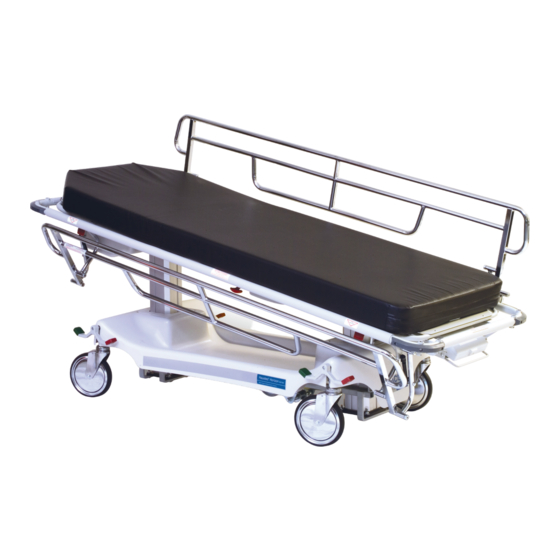
Hausted Horizon Series Operating Manual
Hide thumbs
Also See for Horizon Series:
- Operating manual (24 pages) ,
- Operating manual (32 pages) ,
- Operating manual (44 pages)

Related Manuals for Hausted Horizon Series


Summary of Contents for Hausted Horizon Series
- Page 1 Operating Manual Hausted Horizon Series ® ® Multi-purpose Stretchers – electric powered Models: 4e1 & 4e2 4D1 & 4D2 V2 02.12 069389 HauSteD® patient HanDling SySteMS, llC...
- Page 2 Hausted engineering Service which Hausted carries a complete line of accessories for use this manual is protected by Federal Copyright law, which could affect its operation, will void the warranty, with these stretchers.
-
Page 3: Table Of Contents
+31(0)6 516 536 26 3.4.3 trendelenburg adjustment ............................3-6 3.4.4 reverse trendelenburg adjustment ........................3-6 Manufactured by: 3.5 electric Control locations ............................3-7 Hausted® patient Handling Systems, llC 2511 Midpark road 3.5.1 nurses Control panel ...............................3-7 Montgomery, al 36109 3.5.2 patient pendant .................................3-7 3.5.3 plug locations ................................3-7... - Page 4 taBle OF COntentS 3.8.3 lowering the rail ..............................3-12 3.9 push Handle Operation (Optional accessory)....................3-13 3.9.1 raising the push Handles ........................... 3-13 3.9.2 lowering the push Handles ..........................3-13 3.10 permanently Mounted iV rod Operation ......................3-14 3.10.1 putting i.V. rod in up position ........................3-14 3.10.2 extending i.V.
-
Page 5: Listing Of Warnings And Cautions
Safety precautions must be observed See Section 3 for the warnings below: Floors must be smooth and level to maintain when operating or servicing this Hausted® Horizon® OperatiOn (Continued): warningS – CautiOnS anD prOper optimum fifth wheel steering. Fifth wheel steer- Multi-purpose Stretchers. -
Page 6: Uncrating Instructions
- leave carton intact. leave the equipment in the receiving your Hausted equipment has been carefully packed area until inspection is complete. at our manufacturing plant to ensure safe shipment CautiOn - pOSSiBle eQuipMent to your medical facility. -
Page 7: Operating Instructions
4e2Dpa or 4D2Dpa which states: Maximum patient weight 327 Kilograms (720 lbs.). nOte: all dimensions are specified in inches. all dimension are ±.375 inches. Hausted reserves the right to change specifications without notice. Stretcher weight: 315 lbs. Knee FleX 90°... -
Page 8: Features, Warnings And Proper Operation
B. patient entry, egress and transfer should all dimension are ±.375 inches. Hausted reserves the receptacle, the electric powered stretchers do always be done with the brakes locked. -
Page 9: Braking And Steering Operation
Operating inStruCtiOnS Operating inStruCtiOnS 3.2 FeatureS, warningS anD prOper OperatiOn 3.3 BraKing anD Steering OperatiOn 3.3.1 applying the Brakes the four wheel central braking system is acti- vated by depressing the red pedal at any of the four corners of the unit (Figure 3-1). to fully engage the brakes, the pedal should be pressed Figure 3 - 1 to approximately 45º. -
Page 10: Litter Top Height Adjustment (4E1 Models Only)
Operating inStruCtiOnS Operating inStruCtiOnS 3.4 litter tOp HeigHt aDJuStMent ( 4D1/4e1 MODelS Only ) 3.5 eleCtriC COntrOl lOCatiOnS 3.4.1 Height adjustment 3.5.1 nurses Control panel press the pump pedal to the floor (Figure 3-4), to access the nurses control panel, pull out on then release. - Page 11 Operating inStruCtiOnS Operating inStruCtiOnS 3.5 eleCtriC COntrOl lOCatiOnS 3.6 litter tOp aDJuStMent 3.5.4 emergency electric CautiOn Backrest Override the lock-out controls both the pendant and the unit is equipped with a Fowler backrest the control panel. quick drop handle located under the litter top 3.6.1 Height adjustment at stretcher mid section.
-
Page 12: Airglide Rail Operation
Operating inStruCtiOnS Operating inStruCtiOnS 3.6 litter tOp aDJuStMent 3.6 litter tOp aDJuStMent 3.6.5 trendelenburg adjustment nOte: this unit is equipped with a Fowler backrest quick drop handle located on either side of the stretcher near the foot section (see stretcher (4e2 &... -
Page 13: Retracto Rail Operation
Operating inStruCtiOnS Operating inStruCtiOnS 3.9 puSH HanDle OperatiOn ( OptiOnal aCCeSSOry ) 3.8 retraCtO rail OperatiOn 3.9.1 raising the push Handles warning - perSOnal Hinge the push handle up (Figure 3-30) until inJury HaZarD: it stops. Slide the push handle down into the Be sure rail is locked before leaving patient. -
Page 14: Permanently Mounted Iv Rod Operation
Operating inStruCtiOnS 3.10 perManently MOunteD iV rOD OperatiOn warning - perSOnal inJury HaZarD: Be sure rail is locked before leaving patient. 3.10.1 putting i.V. rod in up position grasp i.V. rod and hinge upward until it stops (Figure 3-32). push down on i.V. rod until it slides firmly into the socket. -
Page 15: Trouble Shooting Guide
Step 3: replace (both) batteries with ‘yuSHa’ #np 1.2-12, 12 volt, 1.2 ah batteries. light on the controller: (Hausted p/n 075759 – 2 required. Step 4: Be sure battery connector in place on left side of batteries. If the pilot light is off: Step 5: replace cover. -
Page 16: Recommended Preventive Maintenance
Steam cleaning and pressure washing of stretcher is not recommended and can void warranty. For more detailed information, please contact: Hausted patient Handling Systems at 877.706.5151 069389 069389... -
Page 17: Optional Accessories
(H) Style tops Monitor Shelves it is recommended that only Hausted approved accessories be used with this device. the use of airglide rail (D) Style tops accessories, transducers, and cables other than those specified by the manufacturer, may result in... - Page 18 reCOMMenDeD replaCeMent partS reCOMMenDeD replaCeMent partS Figure 7 - 1. 4e1 HyDrauliC BaSe aSSeMBly item no. part no. Description units per assembly 068331 aSSeMBly, Base Frame 062672 CaSter, tente, Brake 062671 CaSter, tente, Swivel lock 062659 plate, Caster Bolt lock 062685 SCrew, Hex Head Cap, M8 x 1.25 x 12.00”...
- Page 19 reCOMMenDeD replaCeMent partS Figure 7 - 1. 4e1 HyDrauliC BaSe aSSeMBly item no. part no. Description units per assembly 051308 nyliner, 3/4” 068353 COnneCtOr, release pedal 068350 aSSeMBly, release pedal, left 068351 aSSeMBly, release pedal, right 068377 plate, push 068890 SCrew, Hex Head Cap, #10-32 x 1/2”...
-
Page 20: Recommended Replacement Parts
reCOMMenDeD replaCeMent partS reCOMMenDeD replaCeMent partS Figure 7 - 2. 4e2/4D2 – eleCtriC BaSe aSSeMBly Figure 7 - 2. 4e2/4D2 – eleCtriC BaSe aSSeMBly iMpOrtant nOte: To reduce the risk of electric shock, item no. part no. Description units per assembly do not remove the cover. - Page 21 reCOMMenDeD replaCeMent partS reCOMMenDeD replaCeMent partS Figure 7 - 3. 4e2/4D2 – Dpa tOp aSSeMBly Figure 7 - 3. 4e2/4D2 – Dpa tOp aSSeMBly item no. part no. Description units per assembly 069221 welDMent, top, Head/wide top 069225 welDMent, top, Foot/wide 069234 tOp, Seat Sheet pan/wide 067292...
- Page 22 reCOMMenDeD replaCeMent partS Figure 7 - 3. 4e2/4D2 – Dpa tOp aSSeMBly item no. part no. Description units per assembly 068863 gliDe, plastic 066925 SCrew, Flat Head Socket, 1/4-20 x 1.00" long 068475 tape, Double Sided, 1/4" x 2.0" 075041 COVer, nurse Control panel 075741 aSSeMBly, pendant, (CB-14 Version)
- Page 23 reCOMMenDeD replaCeMent partS reCOMMenDeD replaCeMent partS Figure 7 - 4. 4e2/4D2 – Dpa FOwler aSSeMBly Figure 7 - 4. 4e2/4D2 – Dpa FOwler aSSeMBly item no. part no. Description units per assembly 075015 FraMe, Fowler, electric, wide 066696 pin, Fowler Hinge 069237 SHeet, Fowler Cover, wide 075443...
- Page 24 reCOMMenDeD replaCeMent partS reCOMMenDeD replaCeMent partS Figure 7 - 5. leg SeCtiOn aSSeMBly Figure 7 - 5. leg SeCtiOn aSSeMBly item no. part no. Description units per assembly p69226 welDMent, Knee Frame, wide top p69232 aSSeMBly, Foot Frame, wide top 069229 tOp, Kneeflex Foot Support/wide iMpOrtant nOte:...
- Page 25 reCOMMenDeD replaCeMent partS reCOMMenDeD replaCeMent partS Figure 7 - 6. airgliDe rail aSSeMBly Figure 7 - 6. airgliDe rail aSSeMBly item no. part no. Description units per assembly 068453 welDMent, air glide rail 066619 waSHer, nylon 066616 BOlt, Shoulder, 1/2” x 1-1/2” long 066613 Cap, rail latch 031325...
- Page 26 reCOMMenDeD replaCeMent partS reCOMMenDeD replaCeMent partS Figure 7 - 7. 4e2/4D2 – Dpa COntrOller aSSeMBly Figure 7 - 7. 4e2/4D2 – Dpa COntrOller aSSeMBly ( aFter 5.1.00 ) ( aFter 5.1.00 ) iMpOrtant nOte: To reduce the risk of electric shock, do not remove the item no.
- Page 27 reCOMMenDeD replaCeMent partS reCOMMenDeD replaCeMent partS Figure 7 - 8. Dpa COntrOller aSSeMBly ( BeFOre 5.1.00 ) Figure 7 - 8. Dpa COntrOller aSSeMBly ( BeFOre 5.1.00 ) item no. part no. Description units per assembly 075009 Controller Hanger 068962 COntrOller, CB-10 (Before 10/98) 075044 COntrOller, CB-14 (after 10/98)
-
Page 28: Recommended Replacement Parts
reCOMMenDeD replaCeMent partS reCOMMenDeD replaCeMent partS Figure 7 - 9. Dpa plug anD wiring DiagraM ( aFter 5.1.00 ) Figure 7 - 9. Dpa plug anD wiring DiagraM ( aFter 5.1.00 ) item no. part no. Description units per assembly 063031 ButtOn 065403... - Page 29 reCOMMenDeD replaCeMent partS Figure 7 - 10. Dpa plug anD wiring DiagraM ( BeFOre 5.1.00 ) iMpOrtant nOte: To reduce the risk of electric shock, do not remove the cover. Unit is to be serviced by qualified personnel only. For detailed label locations, see Figure 7-11. Figure 7 - 10.
- Page 30 reCOMMenDeD replaCeMent partS reCOMMenDeD replaCeMent partS Figure 7 - 11. 4D2/4e2 – Dpa laBel lOCatiOnS Figure 7 - 11. 4D2/4e2 – Dpa laBel lOCatiOnS item no. part no. Description units per assembly 4E2 – DPA LABEL Locations 4D2 – DPA LABEL Locations 075836 laBel, Side-electric Stretcher 075831...
- Page 31 reCOMMenDeD replaCeMent partS reCOMMenDeD replaCeMent partS Figure 7 - 12. 4D2/4e2 – HMC tOp aSSeMBly Figure 7 - 12. 4D2/4e2 – HMC tOp aSSeMBly item no. part no. Description units per assembly 075413 welDMent, top 068461 aSSeMBly, roller Bracket, right 068536 aSSeMBly, roller Bracket, left 031057...
- Page 32 reCOMMenDeD replaCeMent partS Figure 7 - 12. 4D2/4e2 – HMC tOp aSSeMBly item no. part no. Description units per assembly 076134 aSSeMBly, Controller, 4e2 (after 5/00) 075497 aSSeMBly, Controller, 4D2, 230 VaC (Before 5/00) 076183 aSSeMBly, Controller, 4D2, 230 VaC (after 5/00) 067292 SCrew, Button Head Socket, 5/16-18 x 3/4”...
- Page 33 reCOMMenDeD replaCeMent partS reCOMMenDeD replaCeMent partS Figure 7 - 13. HMC FOwler aSSeMBly Figure 7 - 13. HMC FOwler aSSeMBly item no. part no. Description units per assembly 075425 Fowler Frame-electric / wide 062037 Shoulder Bolt, 1/2 x 2 065879 Fowler Cover Sheet/wide 075443 nut, Cap, 1/4”...
- Page 34 reCOMMenDeD replaCeMent partS reCOMMenDeD replaCeMent partS Figure 7 - 14. HMC leg SeCtiOn aSSeMBly Figure 7 - 14. HMC leg SeCtiOn aSSeMBly item no. part no. Description units per assembly p65626 welDMent, Knee Frame, extra wide p65629 aSSeMBly, Foot Frame, extra wide 062254 SuppOrt, Kneeflex Foot, extra wide p62261...
- Page 35 reCOMMenDeD replaCeMent partS reCOMMenDeD replaCeMent partS Figure 7 - 15. retraCtO rail aSSeMBly Figure 7 - 15. retraCtO rail aSSeMBly item no. part no. Description units per assembly 075057 aSSeMBly, top Cap, left 075056 aSSeMBly, top Cap, right 068886 riVet, Cherry, Female end 068886 riVet, Cherry, Male end 068882...
- Page 36 reCOMMenDeD replaCeMent partS reCOMMenDeD replaCeMent partS Figure 7 - 16. 4e2/4D2 – HMC COntrOller aSSeMBly Figure 7 - 16. 4e2/4D2 – HMC COntrOller aSSeMBly ( aFter 5.1.00 ) ( aFter 5.1.00 ) iMpOrtant nOte: To reduce the risk of electric shock, do not item no.
- Page 37 reCOMMenDeD replaCeMent partS reCOMMenDeD replaCeMent partS Figure 7 - 17. 4e2/4D2 – HMC COntrOller aSSeMBly Figure 7 - 17. 4e2/4D2 – HMC COntrOller aSSeMBly ( BeFOre 5.1.00 ) ( BeFOre 5.1.00 ) iMpOrtant nOte: To reduce the risk of electric shock, do not item no.
- Page 38 reCOMMenDeD replaCeMent partS reCOMMenDeD replaCeMent partS Figure 7 - 18. HMC plug anD wiring DiagraM ( aFter 5.1.00 ) Figure 7 - 18. HMC plug anD wiring DiagraM ( aFter 5.1.00 ) iMpOrtant nOte: To reduce the risk of electric shock, do not item no.
- Page 39 reCOMMenDeD replaCeMent partS reCOMMenDeD replaCeMent partS Figure 7 - 19. HMC plug anD wiring DiagraM ( BeFOre 5.1.00 ) Figure 7 - 19. HMC plug anD wiring DiagraM ( BeFOre 5.1.00 ) iMpOrtant nOte: To reduce the risk of electric shock, do not item no.
- Page 40 reCOMMenDeD replaCeMent partS reCOMMenDeD replaCeMent partS Figure 7 - 20. 4e2/4D2 – HMC laBel lOCatiOnS Figure 7 - 20. 4e2/4D2 – HMC laBel lOCatiOnS item no. part no. Description units per assembly 4E2 – HMC label Locations 4D2 – HMC label Locations 075836 laBel, Side-electric Stretcher 075831...
- Page 41 reCOMMenDeD replaCeMent partS reCOMMenDeD replaCeMent partS Figure 7 - 21. i.V. rOD aSSeMBly ( aFter 10.1.98 ) Figure 7 - 21. i.V. rOD aSSeMBly ( aFter 10.1.98 ) item no. part no. Description units per assembly 075590 I.V. Rod ASSEMBLY, Airglide Rail Top, Pat Left (After 10/1/98) 075591 I.V.
- Page 42 reCOMMenDeD replaCeMent partS reCOMMenDeD replaCeMent partS Figure 7 - 22. HMC i.V. rOD aSSeMBly ( BeFOre 10.1.98 ) Figure 7 - 22. HMC i.V. rOD aSSeMBly ( BeFOre 10.1.98 ) item no. part no. Description units per assembly 066021 HMC I.V. Rod ASSEMBLY (Before 10/1/98) 066002 aSSeMBly, Hinge 066012...
- Page 43 reCOMMenDeD replaCeMent partS reCOMMenDeD replaCeMent partS Figure 7 - 23. Dpa i.V. rOD aSSeMBly ( BeFOre 10.1.98 ) Figure 7 - 23. Dpa i.V. rOD aSSeMBly ( BeFOre 10.1.98 ) item no. part no. Description units per assembly 066725 DPA I.V. Rod ASSEMBLY (Before 10/1/98) 066727 aSSeMBly, i.V.
- Page 44 reCOMMenDeD replaCeMent partS reCOMMenDeD replaCeMent partS Figure 7 - 24. puSH Bar aSSeMBly ( aFter 6.1.99 ) Figure 7 - 24. puSH Bar aSSeMBly ( aFter 6.1.99 ) item no. part no. Description units per assembly 075665 Push Bar ASSEMBLY, Airglide Rail top (After 6/1/99) 075656 Push Bar ASSEMBLY, Retracto Rail top (After 6/1/99) 065631...
- Page 45 reCOMMenDeD replaCeMent partS reCOMMenDeD replaCeMent partS Figure 7 - 25. HMC puSH Bar aSSeMBly ( BeFOre 6.1.99 ) Figure 7 - 25. HMC puSH Bar aSSeMBly ( BeFOre 6.1.99 ) item no. part no. Description units per assembly 068826 HMC Push Bar ASSEMBLY (Before 6/1/99) 068828 welDMent, push Handle, left 068827...
- Page 46 reCOMMenDeD replaCeMent partS reCOMMenDeD replaCeMent partS Figure 7 - 26. Dpa puSH Bar aSSeMBly ( BeFOre 6.1.99 ) Figure 7 - 26. Dpa puSH Bar aSSeMBly ( BeFOre 6.1.99 ) item no. part no. Description units per assembly 068699 DPA Push Bar ASSEMBLY (Before 6/1/99) 068657 welDMent, push Bar Handle, left 068661...
- Page 47 reCOMMenDeD replaCeMent partS reCOMMenDeD replaCeMent partS Figure 7 - 27. FiFtH wHeel aSSeMBly ( aFter 9.1.99 ) Figure 7 - 27. FiFtH wHeel aSSeMBly ( aFter 9.1.99 ) item no. part no. Description units per assembly 075798 00 Fifth Wheel ASSEMBLY – Horizon Electric (After 9/1/99) 075797 00 Fifth Wheel ASSEMBLY –...
- Page 48 reCOMMenDeD replaCeMent partS reCOMMenDeD replaCeMent partS Figure 7 - 28. FiFtH wHeel aSSeMBly ( aFter 9.1.99 ) Figure 7 - 28. FiFtH wHeel aSSeMBly ( aFter 9.1.99 ) item no. part no. Description units per assembly 075799 00 Fifth Wheel Sub-ASSEMBLY– Horizon Electric (After 9/1/99) 075796 00 Fifth Wheel Sub-ASSEMBLY –...
- Page 49 reCOMMenDeD replaCeMent partS reCOMMenDeD replaCeMent partS Figure 7 - 29. FiFtH wHeel aSSeMBly ( BeFOre 9.1.99 ) Figure 7 - 29. FiFtH wHeel aSSeMBly ( BeFOre 9.1.99 ) item no. part no. Description units per assembly 068516 Fifth Wheel Assembly (Before 9/1/99) aSSeMBly, 4e2 Base 051308 nyliner, Flange, 3/4”...
-
Page 50: Appendix
Hausted Horizon Series Multi-purpose Stretchers are intended for use in the electromagnetic environment specified below. the customer or the user of the Hausted Horizon Series Multi-purpose Stretchers environment specified below. the customer or the user of the Hausted Horizon Series Multi-purpose Stretchers should assure that it is used in such an environment. -
Page 51: Recommended Separation Distances
Hausted Horizon Series Multi-purpose Stretchers are used exceeds the applicable rF compliance level above, the Hausted Horizon Series Multi-purpose Stretchers should be observed to verify normal operation. - Page 52 — provided such equipment has been properly installed and maintained and has not been misused and abused. the determination of proper installation, maintenance and use shall rest solely with Hausted. exempt five year...
- Page 53 Hausted offers annual maintenance agreements to give your capital equipment planned maintenance agreements that will help correct little problems before they become big ones. Hausted engineering Service combines the precise maintenance program and factory-trained technicians to assure you of maximum productivity.
Need help?
Do you have a question about the Horizon Series and is the answer not in the manual?
Questions and answers