
Related Manuals for Hausted Horizon 462 - A


Summary of Contents for Hausted Horizon 462 - A
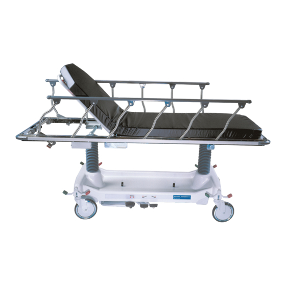
- Page 1 Operating Manual Hausted Horizon Series Stretchers ® Model: 462 – a, C, D, e, F, g and H tops eMp – youth V1 02.11 068499 HauSteD® patient HanDling SySteMS, llC...
- Page 2 WARNING - COPYING PROHIBITED this manual is protected by Federal Copyright law, which provides for damages of up to uSD $20000, as well as criminal fines and imprisonment, for unauthorized copying.
- Page 3 Hausted carries a complete line of accessories for use performed by Hausted engineering Service which with this stretcher. a Hausted representative will gladly could affect its operation will void the warranty, review these with you.
- Page 4 EC Authorized Representative Cepartner4u BV eSDOOrnlaan 13 3951DB Maarn the netherlands +31(0)6 516 536 26 Manufactured by: Hausted® patient Handling Systems, llC 2511 Midpark road Montgomery, al 36109 334.215.5151 Main 877.706.5151 toll Free 334.215.5150 Fax www.Hausted.com equipment not suitable for use in the presence of a flammable anesthetic mixture with air or oxygen or nitrous oxide.
-
Page 5: Table Of Contents
taBle OF COntentS 1 listing of warnings and Cautions ........................ 2 uncrating instructions ............................3 Operating instructions ............................3.1 Braking and Steering Operation ..........................3-1 3.1.1 applying the Brakes ..............................3-1 3.1.2 releasing the Brakes ..............................3-1 3.1.3 applying the Steering lock/Fifth wheel ......................3-2 3.1.4 releasing the Steering lock/Fifth wheel ......................3-2 3.2 litter top Height adjustment ..........................3-3 3.2.1 Height adjustment ..............................3-3... - Page 6 taBle OF COntentS 3.8.2 Storing pushbars ..............................3-10 4 recommended preventive Maintenance ....................5 recommended Optional accessories ......................6 recommended replacement parts ......................7 warranty ................................... 068499...
-
Page 8: Listing Of Warnings And Cautions
OF warningS anD CautiOnS the following Safety precautions must be observed patient entry, egress and transfer should always when operating or servicing Hausted® Horizon Series be done with caster braking system locked. Stretchers . warning indicates the potential for... -
Page 10: Uncrating Instructions
- leave carton intact. leave the equipment in the receiving your Hausted equipment has been carefully packed area until inspection is complete. at our manufacturing plant to ensure safe shipment CautiOn - pOSSiBle eQuipMent to your medical facility. -
Page 12: Operating Instructions
Operating inStruCtiOnS 3.1 BreaKing anD Steering OperatiOn warning–perSOnal inJury HaZarD anD/Or eQuipMent DaMage HaZarD: • Caster braking system should always be locked when patient is not in transport. Figure 3 - 1 • Caster braking system should always be locked and patient side rails up when patient is left unattended. -
Page 13: Applying The Steering Lock/Fifth Wheel
Operating inStruCtiOnS 3.1 BreaKing anD Steering OperatiOn warning–prOper OperatiOn HaZarD: Floors must be smooth and level to maintain optimum fifth wheel steering. Fifth wheel steering functions can be influenced by floor Figure 3 - 3 irregularities (bumps or dips) greater than 1/2"... -
Page 14: Litter Top Height Adjustment
Operating inStruCtiOnS 3.2 litter tOp HeigHt aDJuStMent 3.2.1 Height adjustment press pump pedal to floor (Figure 3-4), then release. repeat this process until desired height is obtained. use smooth strokes on pump pedal to ensure patient comfort. 3.2.2 lowering litter top press down on two release pedals at the Figure 3 - 4 same time (Figure 3-5) until desired height... -
Page 15: Fowler Backrest Operation
Operating inStruCtiOnS 3.3 FOwler BaCKreSt OperatiOn 3.3.1 raising the Backrest grasp fowler backrest frame tube and gas spring activating handle from either side of stretcher. Squeeze handle and tube together and lift. Once desired incline is achieved, release handle. Figure 3 - 4 nOte: the amount of manual lifting required will vary depending on patient size, gas spring is intended only to assist in lifting patient. -
Page 16: Backrest/Knee Flex Operation (Manual Models)
Operating inStruCtiOnS 3.4 BaCKreSt/Knee Flex OperatiOn ( Manual MODelS ) 3.4.1 raising the Backrest/Knee Flex to elevate backrest or knee flex, flip crank handle upwards, and rotate crank handle clockwise. See Figure 3-9. when reaching desired position, stop rotating handle and return crank handle to its original position. -
Page 17: Airglide Rail Operation
Operating inStruCtiOnS 3.5 airgliDe rail OperatiOn 3.5.1 raising the rail refer to Figures 3-11a & 3-11B. grasp rail top tube from under litter top firmly. then pull up until rail locks into full up position. nOte: Verify latching of rail before leaving patient unattended. 3.5.2 lowering the rail Figure 3 - 11a Firmly grasp top of rail, pull out on red tab... -
Page 18: Install Armboard Adaptor And Surgical Bar
Operating inStruCtiOnS 3.5 airgliDe rail OperatiOn 3.5.3 install armboard adaptor and Surgical Bar 1. refer to Figure 3-13. install surgical bar adaptor by positioning adapter over bumper channel and pad. then slide adapter downward until it rests on channel. 2. refer to Figure 3-14. Secure adapter by inserting tethered pin into hole in adaptor. -
Page 19: Retracto Rail Operation
Operating inStruCtiOnS 3.6 retraCtO rail OperatiOn warning–prOper OperatiOn HaZarD: • patient entry, egress and transfer should always be done with caster braking system locked. • Caster braking system should always be locked and patient side rails up when patient is left unattended. Figure 3 - 16 3.6.1 raising the rail grasp rail top cap in the middle of the rail... -
Page 20: Rail Operation (Youth Stretcher)
Operating inStruCtiOnS 3.7 rail OperatiOn ( yOutH StretCHer ) warning–prOper OperatiOn HaZarD: • patient entry, egress and transfer should always be done with caster braking system locked. • Caster braking system should always be locked and patient side rails up when patient is left unattended. -
Page 21: Optional Pushbar Operation
Operating inStruCtiOnS 3.8 OptiOnal puSHBar OperatiOn nOte: refer to puSH HanDle r.r. unitS aSSeMBly, 075656-00 for installation procedure, if necessary. 3.8.1 Deploying pushbars refer to Figure 3-19. grasp handles at the rear of litter top and rotate them 90° upward until fully deployed for use. - Page 22 (pressure washing and steam cleaning are not recommended procedures and can void warranty.) For more detailed information, please contact: Hausted patient Handling Systems at 877.706.5151 068499...
- Page 24 reCOMMenDeD OptiOnal aCCeSSOrieS i.V. poles airglide rail Style tops 066725 Mounted Stainless Steel telescoping in. rod retracto rail Style tops 00e17-00 Stainless Steel 42” long i.V. rod 066000 telescoping i.V. rod Mtd. at Head end w/Bumper – e & g tops 066021 telescoping i.V.
- Page 25 Kit universal 075796 Center track Steering – Model 462 it is recommended that only Hausted approved accessories be used with this device. to order accessories, or for more detailed information on accessories, please contact Hausted at: 1.877.706.5151 068499...
- Page 26 Significant assemblies and components of the Hausted® Horizon Series Stretchers are illustrated and identified in this section. the part number, the description and the quantity required for each usage are given. each indenta- tion in the description represents the assembly level. the unitS per aSSeMBly column is specific for the given assembly or subassembly level.
- Page 27 reCOMMenDeD replaCeMent partS 6.2 liSt OF illuStratiOnS Figure 6-1. Model 462 Base assembly ..............................6-3 Figure 6-2. Model 462 Base assembly ..............................6-5 Figure 6-3. top assembly - Straight (a Style) (part 1 of 3) ......................6-7 Figure 6-3. top assembly - KneeFlex (C Style) (part 2 of 3) ......................6-9 Figure 6-3.
- Page 28 reCOMMenDeD replaCeMent partS Figure 6 - 1. MODel 462 BaSe aSSeMBly Figure 6 - 2. MODel 462 BaSe aSSeMBly 068499...
- Page 29 reCOMMenDeD replaCeMent partS Figure 6 - 1. MODel 462 BaSe aSSeMBly item no. part no. C Description units per assembly MODel 462 BaSe aSSeMBly - nO 5tH wHeel MODel 462 BaSe aSSeMBly - witH 5tH wHeel 150830 BaSe FraMe aSSeMBly 056397 CaSter, BraKe tOtal lOCK 056397...
- Page 30 reCOMMenDeD replaCeMent partS Figure 6 - 1. MODel 462 BaSe aSSeMBly item no. part no. C Description units per assembly 69484 releaSe peDal 031100 nylOn waSHer 068890 Hex HeaD Cap SCrew, #10-32 x 1/2 068377 puSH plate 150830 1/4” StOp COllar 068530 nylOn SHOulDer waSHer 150830...
- Page 32 reCOMMenDeD replaCeMent partS Figure 6 - 1. MODel 462 BaSe aSSeMBly Figure 6 - 2. MODel 462 BaSe aSSeMBly 068499...
- Page 33 reCOMMenDeD replaCeMent partS Figure 6 - 1. MODel 462 BaSe aSSeMBly item no. part no. C Description units per assembly MODel 462 BaSe aSSeMBly - nO 5tH wHeel MODel 462 BaSe aSSeMBly - witH 5tH wHeel 075796 5th wheel Sub-assembly –...
- Page 34 reCOMMenDeD replaCeMent partS Figure 6 - 3. tOp aSSeMBly – StraigHt ( a Style ) ( part 1 OF 3 ) Figure 6 - 3. tOp aSSeMBly – StraigHt ( a Style ) ( part 1 OF 3 ) 068499...
- Page 35 reCOMMenDeD replaCeMent partS Figure 6 - 3. tOp aSSeMBly – KneeFlex ( C Style ) ( part 2 OF 3 ) Figure 6 - 3. tOp aSSeMBly – KneeFlex ( C Style ) ( part 2 OF 3 ) 6-10 068499...
- Page 36 reCOMMenDeD replaCeMent partS Figure 6 - 3. tOp aSSeMBly – KneeFlex ( D extra - wiDe ) ( 3 OF 3 ) Figure 6 - 3. tOp aSSeMBly – KneeFlex ( D extra - wiDe ) ( 3 OF 3 ) 6-11 068499...
- Page 37 reCOMMenDeD replaCeMent partS Figure 6 - 1. MODel 462 BaSe aSSeMBly item no. part no. C Description units per assembly tOp aSSeMBly - StraigHt (a Style) reg. wiDtH tOp aSSeMBly - KneeFlex (C Style) reg. wiDtH tOp aSSeMBly - KneeFlex (D Style) extra wiDe p67103 tOp welDMent, HeaD –...
- Page 38 reCOMMenDeD replaCeMent partS Figure 6 - 3. tOp aSSeMBly – StraigHt ( a Style ) & KneeFlex ( C & D StyleS ) item no. part no. C Description units per assembly 068484 rigHt, tOp angle aSSy. 068483 leFt, tOp angle aSSy. 068495 gaS Spring anCHOr –...
- Page 40 reCOMMenDeD replaCeMent partS Figure 6 - 4. pneuMatiC ( p Style ) - a, C, anD D Style Figure 6 - 4. pneuMatiC ( p Style ) - a, C, anD D Style 6-15 068499...
- Page 41 reCOMMenDeD replaCeMent partS Figure 6 - 4. pneuMatiC ( p Style ) - a, C, anD D Style item no. part no. C Description units per assembly pneuMatiC (p Style) - a & C Style (reg. wiDtH) pneuMatiC (p Style) - D Style (x-wiDe) p68442 FOwler FraMe aSSeMBly –...
- Page 42 reCOMMenDeD replaCeMent partS Figure 6 - 5. StraigHt ( a Style ) rail aSSeMBly this style rail is used on the a, C, and D style tops only Figure 6 - 5. StraigHt ( a Style ) rail aSSeMBly 6-17 068499...
- Page 43 reCOMMenDeD replaCeMent partS Figure 6 - 5. StraigHt ( a Style ) rail aSSeMBly item no. part no. C Description units per assembly StraigHt (a Style) rail aSSeMBly (this style rail is used on the a, C, & D style tops only) 462 Dpa 069238 CrOSStuBe, HeaD enD, welDMent...
- Page 44 reCOMMenDeD replaCeMent partS Figure 6 - 6. StraigHt - tOp aSSeMBlieS Figure 6 - 6. StraigHt - tOp aSSeMBlieS 6-19 068499...
- Page 45 reCOMMenDeD replaCeMent partS Figure 6 - 6. StraigHt - tOp aSSeMBlieS item no. part no. C Description units per assembly StraigHt - tOp aSSeMBlieS - Style e (regular wiDtH) StraigHt - tOp aSSeMBlieS - Style F (extra-wiDe) 031118 Spring pin, 3/16 x 1 150830 HOriZOn tOp welDMent –...
- Page 46 reCOMMenDeD replaCeMent partS Figure 6 - 6. StraigHt - tOp aSSeMBlieS item no. part no. C Description units per assembly 069450 Vinyl Cap rOller BraCKet p65855 SHeet, FOwler COVer – p65879 SHeet, FOwler COVer, x-wiDe – 000794 CHerry riVet, 3/16 x .45 p68929 FOwler aSSeMBly –...
- Page 48 reCOMMenDeD replaCeMent partS Figure 6 - 7. KneeFlex – tOp aSSeMBlieS ( 1 OF 2 ) Figure 6 - 7. KneeFlex – tOp aSSeMBlieS ( 1 OF 2 ) 6-23 068499...
- Page 49 reCOMMenDeD replaCeMent partS Figure 6 - 7. KneeFlex – tOp aSSeMBlieS ( 2 OF 2 ) Figure 6 - 7. KneeFlex – tOp aSSeMBlieS ( 2 OF 2 ) 6-24 068499...
- Page 50 reCOMMenDeD replaCeMent partS Figure 6 - 7. KneeFlex – tOp aSSeMBlieS item no. part no. C Description units per assembly KneeFlex - tOp aSSeMBlieS - Style g (regular wiDtH) KneeFlex - tOp aSSeMBlieS - Style H (extra-wiDe) 031118 Spring pin, 3/16 x 1 150830 HOriZOn tOp welDMent –...
- Page 51 reCOMMenDeD replaCeMent partS Figure 6 - 7. KneeFlex – tOp aSSeMBlieS item no. part no. C Description units per assembly 068887 retraCtO rail aSSeMBly, rigHt 068885 retraCtO rail aSSeMBly, leFt 056397 Knee Flex aSSeMBly – 150830 Knee Flex aSSeMBly, x-wiDe –...
- Page 52 reCOMMenDeD replaCeMent partS Figure 6 - 8. pneuMatiC ( M Style ) Figure 6 - 8. pneuMatiC ( M Style ) 6-27 068499...
- Page 53 reCOMMenDeD replaCeMent partS Figure 6 - 8. pneuMatiC ( M Style ) item no. part no. C Description units per assembly pneuMatiC (M Style) - e & g Style (reg. wiDtH) pneuMatiC (M Style) - F & H Style (x-wiDe) p68907 FOwler FraMe aSSeMBly, uSeD w/retraCtO rail –...
- Page 54 reCOMMenDeD replaCeMent partS Figure 6 - 9. 462eMp yOutH StretCHer Figure 6 - 9. 462eMp yOutH StretCHer 6-29 068499...
- Page 55 reCOMMenDeD replaCeMent partS Figure 6 - 9. 462eMp yOutH StretCHer item no. part no. C Description units per assembly 462eMp yOutH StretCHer BaSe Final aSSeMBly 150830 tOp welDMent, regular wiDtH 068493 HOriZOn tOp retaining plug p69472 rOller BraCKet aSSeMBly 150830 CleViS pin 150830 tOp COVer SHeet...
- Page 56 reCOMMenDeD replaCeMent partS Figure 6 - 10. yOutH VertiCal rail aSSeMBly Figure 6 - 10. yOutH VertiCal rail aSSeMBly 6-31 068499...
- Page 57 reCOMMenDeD replaCeMent partS Figure 6 - 10. yOutH VertiCal rail aSSeMBly item no. part no. C Description units per assembly yOutH VertiCal rail aSSeMBly 128930 SiDe rail aSSeMBly 12893D • lOwer rail 056397 • tuBe aSSeMBly, lOCK, VertiCal 056397 • VertiCal tuBe 12893B •...
- Page 58 reCOMMenDeD replaCeMent partS Figure 6 - 11. tHree - SeCtiOn MOunteD i.V. rOD aSSeMBly ( a, C, D, StyleS ) Figure 6 - 11. tHree - SeCtiOn MOunteD i.V. rOD aSSeMBly ( a, C, D, StyleS ) 6-33 068499...
- Page 59 reCOMMenDeD replaCeMent partS Figure 6 - 11. tHree - SeCtiOn MOunteD i.V. rOD aSSeMBly ( a, C, D, StyleS ) item no. part no. C Description units per assembly tHree-SeCtiOn MOunteD i.V. rOD aSSeMBly (a, C, D, StyleS 066726 i.V. rOD tHree-SeCtiOn aSSeMBly, SHOrt 066731 •...
- Page 60 reCOMMenDeD replaCeMent partS Figure 6 - 12. tHree - SeCtiOn MOunteD i.V. rOD aSSeMBly Figure 6 - 12. tHree - SeCtiOn MOunteD i.V. rOD aSSeMBly 6-35 068499...
- Page 61 reCOMMenDeD replaCeMent partS Figure 6 - 12. tHree - SeCtiOn MOunteD i.V. rOD aSSeMBly item no. part no. C Description units per assembly tHree-SeCtiOn MOunteD i.V. rOD aSSeMBly – StyleS e & g tHree-SeCtiOn MOunteD i.V. rOD aSSeMBly – StyleS F & H 066006 i.V.
- Page 62 reCOMMenDeD replaCeMent partS Figure 6 - 13. 462 FiFtH wHeel Center traCK aSSeMBly ( part 1 OF 3 ) Figure 6 - 13. 462 FiFtH wHeel Center traCK aSSeMBly ( part 1 OF 3 ) 6-37 068499...
- Page 63 reCOMMenDeD replaCeMent partS Figure 6 - 13. 462 FiFtH wHeel Center traCK aSSeMBly ( part 2 OF 3 ) Figure 6 - 13. 462 FiFtH wHeel Center traCK aSSeMBly ( part 2 OF 3 ) 6-38 068499...
- Page 64 reCOMMenDeD replaCeMent partS Figure 6 - 13. 462 FiFtH wHeel Center traCK aSSeMBly ( part 3 OF 3 ) Figure 6 - 13. 462 FiFtH wHeel Center traCK aSSeMBly ( part 3 OF 3 ) 6-39 068499...
- Page 65 reCOMMenDeD replaCeMent partS Figure 6 - 13. 462 FiFtH wHeel Center traCK aSSeMBly item no. part no. C Description units per assembly 462 FiFtH wHeel Center traCK aSSeMBly 134469 linK, SHOrt 075783 linK, lOng 065807 BOlt, SHOulDer 3/8 x 3/8 062684 150830 lOCK nut, 5/16-18...
- Page 66 — provided such equipment has been properly installed and maintained and has not been misused and abused. the determination of proper installation, maintenance and use shall rest solely with Hausted. exempt five year...
- Page 68 Hausted offers annual maintenance agreements to give your capital equipment planned maintenance agreements that will help correct little problems before they become big ones. Hausted engineering Service combines the precise maintenance program and factory-trained technicians to assure you of maximum productivity.
Need help?
Do you have a question about the Horizon 462 - A and is the answer not in the manual?
Questions and answers