Table of Contents
Advertisement
Quick Links
SRS technology Licensed from SRS Labs. SRS technol-
ogy holds the following patents: U.S. Patent No.
4,748,669 and U.S. Patent No. 4,841,572.
SRS, the SRS Logo ( ) and the Sound Retrieval System
are registered trademarks of SRS Labs, Inc. in the United
States.
SAFETY PRECAUTION FOR SEVICE MANUAL ............................................................................................................. 2
VOLTAGE SELECTION .................................................................................................................................................... 2
SPECIFICATIONS ............................................................................................................................................................ 3
NAMES OF PARTS .......................................................................................................................................................... 4
OPERATION MANUAL ..................................................................................................................................................... 6
DISASSEMBLY .................................................................................................................................................................. 7
REMOVING AND REINSTALLING THE MAIN PARTS .................................................................................................... 9
ADJUSTMENT ................................................................................................................................................................ 10
NOTES ON SCHEMATIC DIAGRAM ............................................................................................................................. 12
BLOCK DIAGRAM .......................................................................................................................................................... 13
WAVEFORMS OF CD CIRCUIT ..................................................................................................................................... 16
SCHEMATIC DIAGRAM / WIRING SIDE OF P.W.BOARD ............................................................................................. 17
TROUBLESHOOTING (CD CHANGER CONTROL / CD SECTION) ............................................................................ 34
FUNCTION TABLE OF IC .............................................................................................................................................. 38
FL DISPLAY ..................................................................................................................................................................... 45
REPLACEMENT PARTS LIST/EXPLODED VIEW
SERVICE MANUAL
• In the interests of user-safety the set should be restored to its
CONTENTS
SHARP CORPORATION
- 1 -
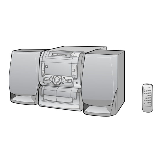
CD-C290X
CD-C290X mini component system consisting of
CD-C290X mini component system,CP-C290
speaker system.
original condition and only parts identical to those specified be
used.
This document has been published to be used
for after sales service only.
The contents are subject to change without notice.
CD-C290X
No. S9910CDC290X
Page
Advertisement
Table of Contents

Related Manuals for Sharp CD-C290X


Summary of Contents for Sharp CD-C290X
-
Page 1: Table Of Contents
CD-C290X SERVICE MANUAL No. S9910CDC290X CD-C290X CD-C290X mini component system consisting of CD-C290X mini component system,CP-C290 speaker system. SRS technology Licensed from SRS Labs. SRS technol- • In the interests of user-safety the set should be restored to its ogy holds the following patents: U.S. Patent No. -
Page 2: Safety Precaution For Sevice Manual
CD-C290X SAFETY PRECAUTION FOR Laser Diode Properties SERVICE MANUAL Material: GaAIAs Wavelength: 780 nm Emission Duration: continuous Laser Output: max. 0.6 mW Precaution to be taken when replacing and servicing the Laser Pickup. The AEL (Accessible Emission Level) of Laser Power Output for this model is specified to be lower than Class I Requirements. -
Page 3: Specifications
CD-C290X FOR A COMPLETE DESCRIPTION OF THE OPERATION OF THIS UNIT, PLEASE REFER TO THE OPERATION MANUAL. SPECIFICATIONS General Compact disc player section Power source: AC 110/127/220/230-240 V, Type: 3-disc multi-play compact disc player 50/60 Hz Signal readout: Non-contact, 3-beam semi-... -
Page 4: Names Of Parts
CD-C290X NAMES OF PARTS CD-C290X Front panel Disc Tray Disc Number Select Buttons Disc Skip Button Open/Close Button: 6 7 8 9 Disc Number Indicator Timer Indicator SLEEP X-BASS Record Indicator Sleep Indicator 10 1112 Extra Bass Indicator: X-BASS Memory Indicator... - Page 5 CD-C290X Rear panel Span Selector Switch Speaker Terminals AC Voltage Selector AC Power Input Socket Video/Auxiliary (Audio Signal) Input Sockets FM 75 Ohms Aerial Terminal Aerial Earth Terminal AM Aerial Terminal CP-C290 Speaker section Tweeter Woofer Bass Reflex Duct Speaker Wire...
-
Page 6: Operation Manual
CD-C290X OPERATION MANUAL – 6 –... -
Page 7: Disassembly
CD-C290X DISASSEMBLY Caution on Disassembly CD-C290X Follow the below-mentioned notes when disassembling the unit and reassembling it, to keep it safe and ensure Top Cabinet excellent performance: ( A1 ) x2 1. Take cassette tape and compact disc out of the unit. - Page 8 CD-C290X ( F1 ) x3 ( K1 ) x1 ø3 x10mm ø3 x10mm Switch PWB ( K2 ) x1 ( F1 ) x3 Front Panel Washer ø3 x10mm ( F2 ) x1 Display ø3 x10mm Turntable Main PWB ( E2 ) x1...
-
Page 9: Removing And Reinstalling The Main Parts
CD-C290X CP-C290X Tweeter STEP REMOVAL PROCEDURE FIGURE Front Speaker 1. Net Frame ....(A1) x1 2. Duct Panel ..... (A2) x1 Net Frame ( A3 ) x4 ( A1 ) x1 3. Screw ..... (A3) x4 ø4x14mm 4. Screw ..... (A4) x4... -
Page 10: Adjustment
CD-C290X ADJUSTMENT TUNER SECTION MECHANISM SECTION • Driving Force Check fL: Low-range frequency fH: High-renge frequency Torque Meter Specified Value • AM IF/RF Play: TW-2412 Tape 1: Over 80 g Signal generator: 400 Hz, 30%, AM modulated Tape 2: Over 80 g... - Page 11 CD-C290X TEST MODE • Setting the test mode Any one of test mode can be set by pressing several keys as follows. <REC. PAUSE> + <DISC SKIP> + <POWER> TEST: CD operation test • TEST mode Function — CD test mode Setting of TEST mode Indication of CD TST mode (Fig.
-
Page 12: Notes On Schematic Diagram
CD-C290X NOTES ON SCHEMATIC DIAGRAM • The indicated voltage in each section is the one measured • Resistor: by Digital Multimeter between such a section and the chas- To differentiate the units of resistors, such symbol as K and sis with no signal given. -
Page 13: Block Diagram
CD-C290X Figure 13 BLOCK DIAGRAM (1/3) – 13 –... - Page 14 CD-C290X SO301 ANTENNA CF351 X351 TERMINAL FM IF FM FRONT END CF302 AM IF FE301 75 OHMS FM IF IN T351 (AC) FM/AM IC303 VR351 FM IF DET/FM MPX/AM IF LA1832 FM MUTE LEVEL AM OSC FMOSC MUTING Q353 Q354...
- Page 15 CD-C290X FL701 31 32 MEMORY –VP Q701 BACK UP (AC) TO CD SECTION TO CD SECTION TO CD SECTION TO POWER SECTION SW720 SW701 SW724 AVDD SW719 IC701 AVREF IX0191AW XL702 SYSTEM CONTROL 4.19MHz MICROCOMPUTER TO CD SECTION RESET 42 41...
-
Page 16: Waveforms Of Cd Circuit
CD-C290X WAVEFORMS OF CD CIRCUIT STOP PLAY FOCUS SERCH 0.5ms 0.50 V 10.0 V IC1 20 F.E 0.5ms 10.0 V 0.5ms 5.0 V 0.50 V IC1 54 DRF 0.5ms 1.00 V PLAY 0.5ms NORMAL DISC 1.00 V TN0=01 20ms 1.00 V 0.5ms... -
Page 17: Schematic Diagram / Wiring Side Of P.w.board
CD-C290X R712 R711 SWITCH PWB-A3 DISPLAY PWB-A2 SW702 SW704 VOLUME DOWN VOLUME UP FW702 SW703 X-BASS EQUALIZER TO MAIN PWB R785 P18 4-A R782 SW724 OPEN/CLOSE SW710 R787 TUNING UP C720 /TIME R814 RX701 C719 R801 R761 C711 SW701 R802... - Page 18 CD-C290X TO DISPLA TO DISPLAY PWB TAPE TAPE P17 1-B P17 1 MECHANISUM MECHANISUM TAPE1 HEAD TAPE2 HEAD P20 4-H P20 5-H FW704 CNS501 FW703 CNS502 CNS704 CNS7 Q581 Q583 Q582 C570 Q584 C572 R570 R510 C511 B C E...
- Page 19 CD-C290X TO DISPLAY PWB TO DISPLAY PWB P17 1-D P17 1-G FW703 FW702 CNS703 CNS702 IC91 1 2 3 4 5 6 7 8 9 CNP2 C533 R531 R539 R537 C535 R551 CNP3 R577 Q575 E C B R575 R555...
- Page 20 CD-C290X POWER PWB-B D903 SW901 VOLTAGE D901 SELECTOR 110V 230-240V PT901 POWER TRANSFORMER MAIN PWB D905 127V P18 3-C 220V CNP901 D907 C910 ZD901 TF901 S0901 AC POWER INPUT SOCKET R905 AC 110/127/220/230-240V R904 50/60Hz TAPE MECHANISM ASSEMBLY TO MAIN PWB...
- Page 21 CD-C290X PICKUP UNIT(306) CNS1A CNS1B TO MAIN PWB P19 12-E CNP1 TO MAIN PWB P19 12-C CNP2 CNS2A CNS2B CNS5 MECHA UP DISC NUMBER SENSOR PWB-E OPEN/CLOSE T/T UP/DOWN LOADING CNS10 TO MAIN PWB P19 12-C SOLENOID SOLM2 CNP10 CD MOTOR PWB-F...
- Page 22 CD-C290X TUNER PWB-C R366 E C B Q354 Q353 R377 E C B R361 C371 C374 CNP303 C373 X351 C368 R357 TO MAIN PWB P19 12-E R356 CF351 CNS303 C356 C354 ZD351 R352 COLOR TABLE C365 C396 R351 C395 BROWN...
- Page 23 CD-C290X IC501 IC303 IC401 IC701 NO. VOLTAGE NO. VOLTAGE NO. VOLTAGE NO. VOLTAGE NO. VOLTAGE NO. VOLTAGE NO. VOLTAGE NO. VOLTAGE 2V(2V) –24.7V 0.41V 2V(2V) –24.7V 2.1V 0.6V 7.2V(8.2V) –24.7V 2.1V 0.5V(0.8V) –24.7V 4.4V 1.8V 2V(2V) –24.7V 2.2V 1.3V 0V(0V) –24.7V...
- Page 24 CD-C290X CD_R R418 TO MAIN PWB(2/3) P27 12-C A_GND C402 0.047 R402 (ML) CD_L 38 39 C442 C404 R404 0.0027 C448 R420 0.047 22/16 100K (ML) RVref C406 C444 RINVIN2 R453 0.047 100P R406 RTOUT 1.2K (ML) C446 RVRIN 10/16...
- Page 25 CD-C290X R420 100K R453 1.2K C452 1/50 C450 100/16 D401 TO MAIN 1SS133 +12V(AUDIO) PWB(3/3) P28 1-E C451 R432 1/50 4.7K MAIN_R TO MAIN A_GND PWB(3/3) P28 1-B MAIN_L R431 C462 4.7K R421 2.2/50 C454 R_IN 100K 2.2/50 R_OUT A_GND...
- Page 26 CD-C290X R1 1K 0.01 KTA1266 GR 47/16 1/50 0.01 – FIN2 – – FIN1 EFBAL – – – FOSTA – DGND TOSTA – 2FREQ 0.1/50 – LASER – 0.033 TE– – FSTA 100K LA9241M 8/12CM 0.001 SERVO AMP. SLOF –...
- Page 27 CD-C290X MAIN PWB-A1(2/3) CD SIGNAL LC78622K SERVO/SIGNAL 0.01 CONTROL EFLG 16.93MHz U-COM SBSY SUB-CODE INTERFACE DEF1 XVSS 3.3M 0.033 X-TAL XOUT GENERATOR 2KX8 0.047 VVSS XVDD ISET MUTER RVDD 0.047 VCO CLOCK ERROR COERECT 2.7K CD_R RCHO OSC CONTROL FLAG CONTROL...
- Page 28 CD-C290X MAIN PWB-A1(3/3) – IC961 LA4450 – POWER AMP. FM SIGNAL C975 1000/25 C963 1/50 MAIN_L TO MAIN PWB(1/3) A_GND C976 C977 P25 12-C 1000/25 MAIN_R (ML) C964 R975 1/50 (1/2W) R973 C979 (1/2W) (ML) CNS702 +12V DISPLAY PWB (MECHA)
- Page 29 CD-C290X HEADPHONE PWB-A4 JK961 HEADPHONES C977 (ML) R981 R975 330 (1/2W) R982 L963 (1/2W) 330 (1/2W) 2.2mmH R973 C979 (1/2W) (ML) SO962 SPEAKER TERMINAL L-CH – SPEAKERS MIN. 4 OHMS – R-CH PT901 POWER TRANSFORMER F901 T3.15A L 250V D901...
- Page 30 CD-C290X FL701 DISPLAY 3 4 5 6 7 8 9 13 14 15 16 17 18 19 22 23 24 25 26 27 28 29 32 33 Q701 KRC107 M R707 100K 1 2 3 4 5 6 7 8 9...
- Page 31 CD-C290X DISPLAY PWB-A2 R710 R711 R712 1.2K 1.8K SW702 SW703 SW704 VOLUME X-BASS/ VOLUME DOWN EQUALIZER SW701 SURROUND R718 R719 R720 R721 R722 R723 1.2K 1.8K 2.2K 3.9K 5.6K SW711 SW710 TUNING SW705 SW706 SW707 SW708 SW709 TUNING DOWN STOP...
- Page 32 CD-C290X TUNER PWB-C D GND D353 A+12V 1SS133 A GND TUN MUTE C391 47/16 R354 R363 3.9K 1.2K R384 C395 L352 R387 0.022 5.6K R385 100µH 11.3V 5.6K (0V) R361 R362 R364 C370 4.7K 4.7K 1.2K 1/50 C358 C372 1/50...
- Page 33 SRS PWB-G C200 100/16 C210 100/16 R200 C201 0.022 IC201 SRS5250S R208 R–IN C202 0.47/50 L–IN PN–IN R207 Q206 R206 KRC107M 3.9K R228 PN–OUT MODE R234 R215 Q205 4.7K K246GR C–OUT C–IN R216 4.7K SRS–ON/OFF R212 4.7K SRS–1/2 S–IN Vref S–OUT C223 R217...
-
Page 34: Troubleshooting (Cd Changer Control / Cd Section)
CD-C290X TROUBLESHOOTING (CD SECTION) When the CD does not function When the CD section does not operate When the objective lens of the optical pickup is dirty,this section may not operate.Clean the objective lens,and check the playback operation.When this section does not operate even after the above step is taken,check the following items. - Page 35 CD-C290X • When the CD tray fails to open or close. Check the OPEN CLOSE SW and the wiring from the IC701 Is there following voltage input in specific state of IC701 pin 19? pin 19 to the OPEN CLOSE SW.
- Page 36 CD-C290X • Playback can only be performed when a disc is loaded. Check the laser diode driver. Is the Focus servo active? (Can you hear it working?) Check the area around IC1(16) - (21) (focus servo circuit). If the disc is not turning, the DRF Does the DRF signal change from "L"...
- Page 37 CD-C290X • Checking the spin system. Play operation is performed without disc. The turntable rotates a little. The spin driver circuit is normal. Check the periphery of IC1 pins 23 to 27, pin 39, and pin 40, IC2 The turntable fails to rotate or rotates at high speed.
-
Page 38: Function Table Of Ic
CD-C290X FUNCTION TABLE OF IC IC2 VHiLC78622K-1:Servo/Signal Control(LC78622K) (1/2) Terminal Name Input/Output Function Pin No. DEFI Input Input terminal of defect detection signal (DEF). (Connected to OV when not used.) Input For PLL Input terminal for test. Pull-down resistor is integrated. Surely connected to 0V. - Page 39 CD-C290X IC2 VHiLC78622K-1:Servo/Signal Control(LC78622K) (2/2) Terminal Name Input/Output Pin No. Function Output Output terminal of subcodes P, A, R, S, T, U and W. SFSY Output Output terminal of synchronous signal of subcode frame. It drops when subcode stands by.
- Page 40 CD-C290X IC1 VHiLA9241M/-1:Servo Amp.(LA9241M) (1/2) Function Port Name Pin No. FIN2 Connection pin for photodiode of pickup. RF signal is generated through addition with FIN pin, and FE signal is generated through subtraction. FIN1 Connection pin for photodiode of pickup.
- Page 41 CD-C290X IC1 VHiLA9241M/-1:Servo Amp.(LA9241M) (2/2) Function Port Name Pin No. Micro computer command clock input pin. Micro computer command data input pin. Micro computer command chip enable input pin. (DETECT RF) RF level detection output. (Focus Serch Select) Pin to switch focus search mode. (± search/+ search for reference voltage) VCC2 VCC pin for servo system and digital system.
- Page 42 CD-C290X IC701 RH-iX0191AWZZ:System Microcomputer (IX0191AW) (1/2) Pin No. Port Name Terminal Name Input/Output Function FIP6-0 FL DRIVER Output Segment Output — Connect with BACK UP VDD TAPE BIAS Output TAPE BIAS ON: H TAPE REC Output TAPE REC. ON:L T1/T2...
- Page 43 CD-C290X IC701 RH-iX0191AWZZ:System Microcomputer (IX0191AW) (2/2) Function Pin No. Port Name Terminal Name Input/Output P124 TAPE1 RUN PULSE Input TAPE1 Run pluse P123 TAPE MECHA STOP Input Tape mecha up state: L 58-60 P122-P120 DISC1-DISC3 Output LED drive output 61-70...
- Page 44 CD-C290X IC201 VHiSRS5250S-1:SRS(SRS5250S) Terminal Name Input/Output Function Pin No. — 8 to 13V supply PN IN Input Signal Input from Perspective Network PN OUT Output Signal Output to Perspective Network Input Constant Phase Filter Capacitor 1 Input Constant Phase Filter Capacitor 2...
-
Page 45: Fl Display
CD-C290X IC5 VHiM56748FP-1: Focus/Tracking/Spin/Slide Driver (M56748FP) Vref-in Stand Vref-in Standby Vref-out SS.GND Vref-out Standby Gain1 Gain4 Gain1 Gain4 Vctl1(–) Vctl4(–) VM1(–) VM4(–) VM1(–) VM4(–) VM1(+) VM4(+) VM1(+) VM4(+) VM2(+) VM3(+) VM2(+) VM3(+) VM2(–) VM3(–) VM2(–) VM3(–) Vctl2(–) Vctl3(out) Vctl3(out) Gain2 Vctl3(–) - Page 46 “HOW TO ORDER REPLACEMENT PARTS” To have your order filled promptly and correctly, please furnish the For U.S.A. only following information. Contact your nearest SHARP Parts Distributor to order. 1. MODEL NUMBER 2. REF. No. 3. PART NO. 4. DESCRIPTION For location of SHARP Parts Distributor, Please call Toll-Free;...
- Page 47 CD-C290X PRICE PRICE DESCRIPTION DESCRIPTION PART CODE PARTS CODE RANK RANK INTEGRATED CIRCUITS T306 RCILB1074AFZZ AC OSC,AM T351 RCILI0011AWZZ AD AM IF VHILA9241M/-1 AS Servo Amp.,LA9241M COILS VHILC78622K-1 AY Servo/Signal Control,LC78622K VHIM56748FP-1 AR Focus/Tracking/Spin/Slide Driver,M56748FP VP-CH270K0000 AB 2.7 µH,Choke IC91...
- Page 48 CD-C290X PRICE PRICE PART CODE DESCRIPTION PARTS CODE DESCRIPTION RANK RANK C224 VCEAZA1HW225M J AB 2.2 µF,50V,Electrolytic C563 VCTYPA1CX823K AB 0.082 µF,16V C301 VCKYMN1HB102K J AA 0.001 µF,50V C564 VCEAZA1CW226M J AC 22 µF,16V,Electrolytic C321 VCEAZA1CW107M J AC 100 µF,16V,Electrolytic...
- Page 49 CD-C290X PRICE PRICE DESCRIPTION DESCRIPTION PART CODE PARTS CODE RANK RANK R36,37 VRD-MN2BD473J AA 47 kohms,1/8W R420 VRD-MN2BD104J AA 100 kohm,1/8W VRD-MN2BD333J AA 33 kohms,1/8W R421 VRD-ST2CD104J AA 100 kohm,1/6W R39,40 VRD-ST2CD223J AA 22 kohms,1/6W R425~427 VRD-ST2CD102J AA 1 kohm,1/6W VRD-MN2BD472J AA 4.7 kohms,1/8W...
- Page 50 CD-C290X PRICE PRICE PART CODE DESCRIPTION PARTS CODE DESCRIPTION RANK RANK R774 VRD-MN2BD103J AA 10 kohm,1/8W FWM2 ———— — Flat Cable,2Pin R775,776 VRD-MN2BD102J AA 1 kohm,1/8W (Supplies at REF No.203) R777,778 VRD-MN2BD103J AA 10 kohm,1/8W JK961 QJAKM0004AWZZ J AK Jack,Headphones...
- Page 51 CD-C290X PRICE PRICE DESCRIPTION DESCRIPTION PART CODE PARTS CODE RANK RANK 92LMTR1858CASY J AS Motor with Chassis [Disc] 92LCAUT1706B AA Label,CD Laser Caution Mark 92LMTR1854BASY J AP Motor with Gear [Sled] PMAGF0001AWZZ J AF Magnet 92LSUPT1749D AA Support,Magnet QSW-F9001AW01 AD Switch,Leaf Type [Pickup In] JKNBZ0472AWSB AG Button,DISC No.
- Page 52 CD-C290X PRICE PRICE PART CODE DESCRIPTION PARTS CODE DESCRIPTION RANK RANK 92LBAG1460C1 AB Polyethylene Bag,Operation 411-0064 Polyethylene Bag Manual [Front Speaker] AB Polyethylene Bag,AC Power RRMCG0161AWSA J AU Remote Control Supply Cord [Hong Kong Only] 92LLID1782A AQ Battery Lid,Remote Control AA Bag,Plug Adaptor P.W.B.
- Page 53 CD-C290X CD-C290X 620x6 611x2 615x2 613x3 PWB-A1 PWB-A2 257x2 614x2 PWB-A3 258x2 (LUG961,962) Silicon FL701 613x3 Grease PWB-A4 616x2 201-1 616x2 201-2 613x6 TAPE MECHANISM 270x2 610x6 (203-1,203-2, 615x2 203-3,203-4, 203-5,203-6, 201-3 203-7,203-8) PWB-B 201-3 257x4 PWB-C 615x3 Figure 7 CABINET EXPLODED VIEW (1/2) –...
- Page 54 CD-C290X CD-C290X 612x2 612x2 253x2 MECHANISM 606x2 PWB-G 609x4 PWB-E SOLM2 Figure 8 CABINET EXPLODED VIEW (2/2) – 8 – – 54 –...
- Page 55 CD-C290X CP-C290 SP3,4 904x4 Capacitor 904x4 SP1,2 TWEETER SP3 (L-CH) SP4 (R-CH) Capacitor TWEETER SP3 (L-CH) SP4 (R-CH) BLACK Capacitor WOOFER SP1 (L-CH) SP2 (R-CH) WOOFER SP1 (L-CH) SP2 (R-CH) Figure 9 SPEAKER EXPLODED VIEW – 55 – – 9 –...
- Page 56 SHARP-ROXY CORP. (M) SDN BHD Engineering 1 Department Lot 202, Bakar Arang Ind. Est, 08000, Sungai Petani, Kedah, Malaysia.
Need help?
Do you have a question about the CD-C290X and is the answer not in the manual?
Questions and answers