Table of Contents
Advertisement
IMPORTANT SERVICE NOTES (FOR U.S.A. ONLY) ...................................................................................................... 2
SPECIFICATIONS ............................................................................................................................................................ 2
NAMES OF PARTS .......................................................................................................................................................... 3
OPERATION MANUAL ..................................................................................................................................................... 5
DISASSEMBLY ................................................................................................................................................................. 8
REMOVING AND REINSTALLING THE MAIN PARTS .................................................................................................. 11
CD CHANGER MECHANISM MAIN BASE PARTS ASSEMBLING/ADJUSTING PROCEDURE ................................. 13
ADJUSTMENT ................................................................................................................................................................ 20
TEST MODE ................................................................................................................................................................... 21
ERROR MESSAGE LIST ................................................................................................................................................ 24
NOTES ON SCHEMATIC DIAGRAM ............................................................................................................................. 25
TYPES OF TRANSISTOR AND LED .............................................................................................................................. 25
BLOCK DIAGRAM .......................................................................................................................................................... 26
SCHEMATIC DIAGRAM ................................................................................................................................................. 32
WIRING SIDE OF P.W.BOARD ...................................................................................................................................... 43
WAVEFORMS OF CD CIRCUIT ..................................................................................................................................... 52
TROUBLESHOOTING .................................................................................................................................................... 53
FUNCTION TABLE OF IC .............................................................................................................................................. 55
LCD DISPLAY ................................................................................................................................................................. 62
PARTS GUIDE/EXPLODED VIEW
SERVICE MANUAL
CONTENTS
SHARP CORPORATION
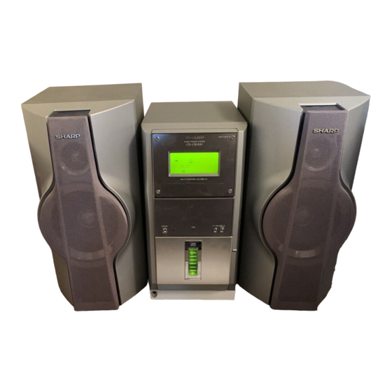
AUDIO TOWER SYSTEM
CD-CH1000
MODEL
CD-CH1000 Audio Tower System consisting of CD-CH1000 (main
unit) and CP-RW5000 (speaker system).
• In the interests of user-safety the set should be restored to its original
condition and only parts identical to those specified should be used.
This document has been published to be used
for after sales service only.
The contents are subject to change without notice.
CD-CH1000
No. S8070CDCH1000
Page
Advertisement
Table of Contents

Related Manuals for Sharp CD-CH1000


Summary of Contents for Sharp CD-CH1000
-
Page 1: Table Of Contents
AUDIO TOWER SYSTEM CD-CH1000 MODEL CD-CH1000 Audio Tower System consisting of CD-CH1000 (main unit) and CP-RW5000 (speaker system). • In the interests of user-safety the set should be restored to its original condition and only parts identical to those specified should be used. -
Page 2: Important Service Notes (For U.s.a. Only)
CD-CH1000 FOR A COMPLETE DESCRIPTION OF THE OPERATION OF THIS UNIT, PLEASE REFER TO THE OPERATION MANUAL. IMPORTANT SERVICE NOTES (FOR U.S.A. ONLY) BEFORE RETURNING THE AUDIO PRODUCT (Fire & Shock Hazard) Before returning the audio product to the user, perform the following safety checks. -
Page 3: 15. Cd Repeat Indicator
CD-CH1000 NAMES OF PARTS CD-CH1000 Front panel Cassette Compartment Volume Up/Demo Button Volume Down Button Timer Set Indicator Power Button CD Direct Play Buttons (with Indicator)/ CD Eject Buttons Disc Trays Headphone Jack Control Panel Open/Close Button CD Play Mode Select Button... - Page 4 CD-CH1000 CD-CH1000 Remote control Remote Control Transmitter Tuner (Band) Button CD Button Auxiliary Button CD Direct Play Buttons Memory Button Clear Button Fast Reverse/Preset Down Button Enter Button Stop Button Menu Button Control Panel Open/Close Button Tape Button Power Button...
-
Page 5: Operation Manual
CD-CH1000 OPERATION MANUAL Setting the Clock Turn the jog dial to adjust the hour and within 2 minutes, press the ENTER button. When the 12-hour display is selected, “AM” will change automatically to “PM”. Turn the jog dial to adjust the minutes and within 2 minutes, press the ENTER button. -
Page 6: System Connections
CD-CH1000 Accessories Accesorios Blue Rojo Azul Black Black Negro Negro Speaker wire for Speaker wire for MAIN terminals × 2 SUBWOOFER terminals × 2 Remote control × 1 FM/AM loop antenna × 1 Controlador remoto × 1 Antena de FM/cuadro de AM × 1... -
Page 7: Listening To A Cassette Tape
CD-CH1000 Listening to a CD (CDs) Listening to a Cassette Tape Audición de un disco CD (CDs) Audición de un cassette Press the POWER button to turn the Press the POWER button to turn the power on. power on. Pulse el botón POWER para conectar Pulse el botón POWER para conectar... -
Page 8: Disassembly
CD-CH1000 DISASSEMBLY CD-CH1000 Caution on Disassembly Follow the below-mentioned notes when disassembling the unit and reassembling it, to keep it safe and ensure Top Cabinet (A1)x2 excellent performance: Front Panel ø3x16mm 1. Take cassette tape and compact disc out of the unit. - Page 9 CD-CH1000 Control PWB (G2)x1 Speaker Control Panel B ø3x10mm (G2)x1 Jog PWB (S1)x6 ø3x10mm Power PWB ø2.6x10mm (U1)x2 ø2.6x10mm (G1)x1 (U1)x1 ø2.6x10mm Main (S2)x1 Chassis (T1)x6 ø2.6x10mm LED B PWB CD Changer Block LED Holder Figure 9-1 Front Panel Cassette...
- Page 10 CD-CH1000 CP-RW5000 CD-CH1000 (CD CHANGER MECHANISM UNIT) PROCEDURE STEP REMOVAL FIGURE STEP REMOVAL PROCEDURE FIGURE Woofer/Tweeter/ 1. Net ....(A1) x1 10-3 Top Cabinet 1. Screw ....(A1) x5 Sub Woofer 2. Front Panel ..(A2) x1 Side Panel(Left/Right) 1. Screw ....(B1) x8 3.
-
Page 11: Removing And Reinstalling The Main Parts
CD-CH1000 REMOVING AND REINSTALLING THE MAIN PARTS TAPE MECHANISM SECTION Perform steps 1 to 4 and 8 of the disassembly method to Record/Playback Head remove the tape mechanism. How to remove the record/playback and erase heads (See Fig. 11-1) 1. Carefully remove the record/playback head and erase head screws (A1) x 2 pcs. -
Page 12: Front Panel Section
CD-CH1000 FRONT PANEL SECTION (E1)x1 CD Changer ø2.6x10mm Door Panel Perform steps 1 to 4 of the disassembly method to remove the front panel. Gear Box A How to remove the control panel motor (See Fig. 12-1) Control 1. Remove the control panel. -
Page 13: Cd Changer Mechanism Main Base Parts Assembling/Adjusting Procedure
CD-CH1000 CD CHANGER MECHANISM MAIN BASE PARTS ASSEMBLING/ADJUSTING PROCEDURE Work content Applied part No. Assembly fig. No. Remarks 1. Motor assembly (X 2) mounting (screw x 4) 101/129 Fig.14 2. MT idle gear mounting (screw x 1) Fig.14 3. MT system gear assembly 123/124/126/127 Fig.14... - Page 14 CD-CH1000 STB DRIVE GEAR R STB GEAR D STB HOLDER MAIN BASE (ASSY) STB DRIVE GEAR A Mark position STB GEAR A STB GEAR ANG. STB GEAR B STB GEAR C STB DRIVE GEAR A STB DRIVE GEAR L TRAY GEAR C...
- Page 15 CD-CH1000 Mark position * This position becomes the reference (stock) position of the tray. TRAY GEAR A The hole must align. It must not rotate in contact with the peripheral (hatched) part of 131. TRAY GEAR B Direct the recess part...
- Page 16 CD-CH1000 Mark position (Assemble the mode big gear in this position.) CHANGE BOX R Note To assemble the mode big gear, incline it, bring it into contact with the circumference and put the center hole into position since the MT IDLER GEAR F...
- Page 17 CD-CH1000 37° Mark position LIFT GEAR A TRAY DRIVE GEAR F CHANGE BOX L Direct the recess part (trapezoidal side) of the axis 135 in this direction. TRAY JOINT GEAR F LIFT CAM Scale: 2 magnifications TRAY JOINT GEAR F...
- Page 18 CD-CH1000 TOP PLATE F Mark position LIFT GEAR A STB HOLDER HEIGHT ADJUSTING METHOD When the height of When the height of Adjusting procedure STB holder is high, STB holder is low, 1. Turn the mode big gear approx. 37 degrees in the arrow direction.
- Page 19 CD-CH1000 Mark position Be sure to assemble the tray into this position. 191~196 TRAY1~TRAY6 Insert it along the guide of the change box. LIFT GEAR A TRAY No.1~6 Rear side Rear surface: Stamped. Note: During insertion, don't mistake No. Tray installing method: (After adjusting the height of the STB holder) 1.
-
Page 20: Adjustment
CD-CH1000 ADJUSTMENT MECHANISM SECTION TUNER SECTION fL: Low-range frequency • Driving Force Check fH: High-range frequency Torque Meter Specified Value • AM IF/RF Play: TW-2412 Over 80 g Signal generator: 400 Hz, 30%, AM modulated • Torque Check Frequency Frequency... -
Page 21: Test Mode
CD-CH1000 TEST MODE Outline While the unit is turned off, press the POWER key while holding down the VOLUME-DOWN and PANEL OP/CL keys to enter the test mode selection mode. Then, the unit is started, the panel is opened, and the microcomputer's version/destination/span is displayed. - Page 22 CD-CH1000 2. Soft reset Purpose: To initialize the unit. Function: To initialize all functions. Operation: "ALL CLEAR" is displayed, all functions are initialized, and the unit is turned on. To exit the test mode When the initialization through soft reset is complete, the unit is turned on.
- Page 23 CD-CH1000 (3) Step 3 mode Performs focus search and turns on the focus servo. Focus search is repeated until it is brought into focus. Display "T3___________0:00" The keys you can press here and the resulting operations are as follows: "POWER" ... The test mode is turned off, the power is turned off, and the unit is placed in the normal standby mode.
-
Page 24: Error Message List
CD-CH1000 Table 24. TEST-TuSet preset frequencies Unused channels are indicated with "_". BAND U.S.A. '%' indicates the last channel for each band. FM 87.5 MHz All FM bands are preset to FM monaural. FM108.0 MHz FM 90.0 MHz FM106.0 MHz FM 98.0 MHz... -
Page 25: Notes On Schematic Diagram
CD-CH1000 NOTES ON SCHEMATIC DIAGRAM • The indicated voltage in each section is the one measured • Resistor: by Digital Multimeter between such a section and the chas- To differentiate the units of resistors, such symbol as K and M are used: the symbol K means 1000 ohm and the symbol sis with no signal given. -
Page 26: Block Diagram
CD-CH1000 SWITCHING Q351 (FM/AM) MO/ST TUN_L PHASE L-CH OUT D_GND TUN_R R-CH OUT A_+B C2B_CE PHASE C2B_CL MPX IN IF OUT C2B_DO Q360 SWITCHING C2B_DI X351 CF351 456kHz FM IF FM DET STEREO FM/AM OUT CF352 AM LOW CUT AM IF IN... - Page 27 CD-CH1000 TO MICOM SECTION A_GND TAPE_R TAPE_L Q507 REC_R-CH Q508 REC_L-CH Y X W REC_L-CH IC503 NJM4558M MOTOR DRIVER – – REC_L-CH D_GND C2B_DO C2B_CL C2B_DI C2B_CE CD_L CD_R TUNER_L TUNER_R TUNER TAPE_L TAPE_R DECK AUX_L AUX_R CD_R RSEL0 LSEL0...
- Page 28 CD-CH1000 9 8 7 6 5 4 3 30 29 28 27 26 25 24 23 22 21 20 19 18 17 16 15 14 13 12 11 10 LCD E TIMER LCD BACK LED CONT SYS MUTE 30 LCD R/W...
- Page 29 CD-CH1000 IC702 RX701 REMOTE IC912 INPUT/OUTPUT SENSOR BU2092F DATA EXPANDER SW12 INPUT/OUTPUT BU2092F SW11 EXPANDER SW10 DATA CLOCK CNS720 CD-R_SEL A_+B D_+B D_GND SW701 REMOCON POWER POW_KEY POW_IND DATA 7 6 5 4 3 2 1 Q725 Q723 Q721 SW710,...
- Page 30 CD-CH1000 Q200 MO200 JK701 MOTOR HEADPHONES Q212 SO201 SP L-CH MAIN SP L-CH Q210 SP L-CH SO201 SPEAKER TERMINALS SP L-CH WOOFER SP R-CH RY202 SP R-CH SP R-CH MAIN SP R-CH AC POWER SUPPLY Q209 RY801 CORD F807 RY201...
- Page 31 CD-CH1000 MOB2 MOB1 SPINDLE SLED TRAY MOTOR MOTOR MAIN CAM MOTOR MOTOR NSW1 PICKUP IN – – – – BIAS BIAS LOADING1 POWVCC VREFSW PREVCC BIAS MUTE PREVCC POWVCC LOADING2 BIAS SWITCHING BIAS PVDD VREF /UHSO RFGC /HSO TEBC SBSY...
-
Page 32: Schematic Diagram
CD-CH1000 FM/AM LOOP ANTENNA AM SIGNAL FM SIGNAL 1 2 3 CNP303 D310 BAND DS1SS133 C301 BF301 PASS C314 0.001 FILTER 0.0047 C303 C308 C315 10P(CH) C304 0.0047 5P(CH) 0.8V 0.01 FMRF C316 C306 L312 1.6V 0.001 R311 3.6V C389... - Page 33 CD-CH1000 JK501 TO TUNER SECTION P32 1-G AUX IN L-CH R-CH L M N K H E G F I MAIN PWB-A (2/3) CHASSIS R550 R549 C541 C540 390P 390P L501 L502 2.2µH 2.2µH R547 R548 2.2K 2.2K C573 C574 2.2/50...
- Page 34 CD-CH1000 C950 C958 150P C957 390P (CH) 150P (CH) R1031 EX-DATA EX-CLK R1007 LCK1 1.1V R1008 R1141 R1068 R1124 R1022 C936 LCD-RW 100P (CH) 30 29 28 27 26 25 24 23 22 21 20 19 18 17 16 15 14 13 12 11 10...
- Page 35 CD-CH1000 IC912 MAIN PWB-A (3/3) C958 BU2092F 390P C970 INPUT/OUTPUT EXPANDER DATA R1032 1K DIG_SEL SW12 AUX_SEL R1052 1K SW11 2.8V R1051 1K 1.1V SW10 PNL_OP R1050 1K PNL_CL R1023 1K P_CONT R1026 R1027 R1048 R1024 CD-R_SEL LCD_RESET C975 C976...
- Page 36 CD-CH1000 DISPLAY PWB-B1 Q707 LED A PWB-B2 KTC3203 Y 0.2V BI702 CNS702 R749 R788 R748 DIMMER DIMMER VLCD A_+B L703 A_+10 2.2µH TO MAIN PWB D_GND 0.1V D_GND LCD720 L704 CNP935A D_+5 C716 LCD DISPLAY 2.2µH 3.1V 2.2/50 P35 12-G 3.4V...
- Page 37 CD-CH1000 MOTOR PWB-B7 SW705 OPEN/CLOSE CNS741 BI741 OPEN_SW SWITCH PWB-B8 TO MAIN PWB CLOSE_SW D_GND CNP933 MOTOR_+ P35 12-H MOTOR_– – C715 MO700 CONTROL PANEL MOTOR FM SIGNAL HEADPHONES PWB-B9 CNS730 BI730 TO POWER JK701 RA711 HEADPHONES L705 CNP207 2.2µH...
- Page 38 CD-CH1000 CD SIGNAL FFC901 CNP1 CD_+B TP7 TP8 CD_GND 0.022 470P CD_R-CH 0.022 PU-IN CORE1 0.047 0.047 CD_L-CH BUS0 TP10 5.6K 0.047 0.047 BUS1 CD/CD-RW_SEL BUS2 TO MAIN PWB 0.001 BUS3 100/10 BUCK CNP901 0.0047 48 47 46 45 44 43 42 41 40 39 38 37 36 35 34 33 0.001...
- Page 39 CD-CH1000 TRAY SWITCH C95 100P PWB-F CNP2 C94 100P GND(D) GND(D) 100P CANA_A CAMA_A SWB104 MODE1 CANA_B SWB105 MODE2 CAMA_B CANA_C SWB106 MODE3 CAMA_C CANA_D SWB107 MODE4 CAMA_D CANA_E CAMA_E SWB108 MODE5 CANB_A CAMB_A SWB109 TRAY1 CANB_B CAMB_B SWB110 TRAY2...
- Page 40 CD-CH1000 IC202 IC201 STK40204(2Ch) STK40271(2Ch) POWER AMP. POWER AMP. +Vcc –Vcc +Vcc R220 R229 0.22 C201 0.22(2W) R216 R215 (2W) C210 R230 C232 C238 C202 220P C209 C206 100/50 C236 0.22(2W) 220P 100/50 220P 100/50 R244 R202 FR213 R201 FR252...
- Page 41 CD-CH1000 POWER PWB-D1 (1/2) (2Ch) –Vcc C231 220P C237 100/50 C235 R247 FR251 C242 C241 C233 R249 R243 100 Fusible 10/50 1/50 10/50 Q208 D206 KTC3199 GR R255 DS1SS133 0.1(1W) 4.6V R264 R259 C239 4.6V 0.022 MO200 R207 R281 DZ201...
-
Page 42: Tape Mechanism
CD-CH1000 FROM P40 1-F CNS940 P35 9-H MAIN PWB TO POWER SECTION CNP102 1 2 3 4 5 6 7 8 A B C D C134 47/25 BIAS OSC. SWITCHING Q116 L104 KTC3203 Y 330µH Q115 KRC104 M R148 R153... -
Page 43: Wiring Side Of P.w.board
CD-CH1000 LED A PWB-B2 LED708 LED702 LED705 LED701 LED709 LED707 LED704 LED706 LED703 LED720 LED723 LED717 LED724 LED722 LED721 LED719 LED718 LED716 BI703B R724 R732 R744 R727 R741 R743 DISPLAY PWB-B1 BI703A R719 R718 L704 L703 R788 C706 C705 C704... - Page 44 CD-CH1000 CD SWITCH PWB-B3 LED759 SW730 SW701 POWER PLAY Q725 R708 SW720 R707 EJECT RX701 LED758 SW731 PLAY R702 R710 C708 SW721 EJECT R703 CNS720 LED757 SW732 PLAY TO MAIN PWB CNP931 SW722 P46 2-A EJECT R791 R714 SW733 R715...
- Page 45 CD-CH1000 CONTROL PWB-B4 JOG PWB-B5 SW758 STOP R777 R781 R779 SW756 R783 PLAY/ PAUSE SW778 ENTER LED773 LED776 R769 R758 SW755 FAST SW753 FORWARD FAST REVERSE JOG701 JOG DIAL LED775 LED774 SW776 SW774 MENU DISPLAY R755 R752 SW752 SW751 SW750...
- Page 46 CD-CH1000 TO TAPE MECHANISM PWB TO POWER PWB FROM JOG PWB FROM DISPLAY PWB P43 11-F P51 12-E P43 7-F P45 11-E CNP807 CNS702 CNS770 FROM FFC970 FROM MOTOR PWB CD SWITCH PWB P44 1-D P45 8-F CNS720 CNP741 8 7 6 5 4 3 2 1...
- Page 47 CD-CH1000 TO POWER PWB P51 12-D CNP806 151413121110 9 8 7 6 5 4 3 2 1 C338 BI960 T302 FM/AM T306 ANTENNA FM MUTE LEVEL C332 VD301 VR351 TP302 L353 IC301 BF301 T311 C306 R302 R314 C324 Q351 R325...
- Page 48 CD-CH1000 TO MAIN PWB CNP901 P46 6-H FFC901 CD PWB-C CNP1 9 11 13 15 17 19 21 23 25 27 29 31 33 8 10 12 14 16 18 20 22 24 26 28 30 32 B C E...
- Page 49 CD-CH1000 MOB2 MOB1 TRAY MOTOR MAIN CAM MOTOR CNS4 SLED MOTOR CNS6A CNS6B SPINDLE MOTOR NSW1 PICKUP IN CNS5A CNS5B CD MOTOR PWB-E CNS7A CNS7B PICKUP UNIT SWB103 DISC DETECT3 COLOR TABLE BROWN SWB102 DISC DETECT2 RD(R) 7 6 5 4 3 2 1...
- Page 50 CD-CH1000 SO201 SPEAKER TERMINALS MAIN SUB WOOFER MAIN R-CH GND R-CH L-CH L-CH SPEAKER PWB-D3 L201 L202 L204 BI201B L203 AC POWER SUPPLY CORD AC 120V, 60Hz CNS808 T801 MAIN POWER TRANSFORMER F807 5A 125V BI808 T802 SUB POWER C836...
- Page 51 CD-CH1000 POWER PWB-D1 COLOR TABLE R248 IC202 BROWN C243 R265 C236 R250 RD(R) R260 RY201 ORANGE R256 C255 R246 YELLOW R274 C234 GREEN R273 C238 BLUE BI201A R266 R255 C244 VIOLET R259 R271 GRAY R257 C242 R275 R263 WH(W) WHITE...
-
Page 52: Waveforms Of Cd Circuit
CD-CH1000 WAVEFORMS OF CD CIRCUIT STOP PLAY NO DISC FOCUS SEARCH IC2 33pin TMAX IC2 17pin IC5 2pin SBOK IC2 8pin IC5 1pin IC2 41pin 0.2µs 0.2µs STOP PLAY FOCUS SEARCH TOC IL IC2 31pin IC2 38pin IC2 34pin IC2 29pin... -
Page 53: Troubleshooting
CD-CH1000 TROUBLESHOOTING When the CD does not function When the CD section does not operate when the objective lens of the optical pickup is dirty, this section may not operate. Clean the objective lens, and check the playback operation. When this section does not operate even after the above step is taken, check the following items. - Page 54 CD-CH1000 Check in the CD test mode. STEP 1 Does the display "E-CD01" appear? Check the line of PU-IN SW. Check from pin 2 of CNP6 via pin 25 of CNP1 to pin 94 of IC901. Does the pickup move to the inner/outer position using the Check the line of the slide control.
-
Page 55: Function Table Of Ic
CD-CH1000 FUNCTION TABLE OF IC IC2 VHiTC9490F/-1: Servo/Signal Control (TC9490F) (1/2) Function Terminal Name Pin No. Input/Output Output Bit clock output terminal. 32fs, 48fs or 64fs can be selected by command. LRCK Output L/R channel clock output terminal. L channel: "L", R channel: "H". - Page 56 CD-CH1000 IC2 VHiTC9490F/-1: Servo/Signal Control (TC9490F) (2/2) Function Terminal Name Input/Output Pin No. AVDD3 — Analog 3.3V power supply terminal. Output Feed equalizer output terminal. Output Disc equalizer output terminal. VSS3 — Digital GND terminal. VDD3 — Digital 3.3V power supply terminal.
- Page 57 CD-CH1000 IC6 VHiTA2147F/-1:Servo Pre Amp. (TA2147F) Function Pin No. Terminal Name Input/Output — 3.3V power supply terminal Input Main beam amp input terminal Input Main beam amp input terminal Input Sub-beam amp input terminal Input Sub-beam amp input terminal Input...
- Page 58 CD-CH1000 IC6 VHiTA2147F/-1:Servo Pre Amp. (TA2147F) PEAK RFDC GVSW 20µ 1.3V RFRP BOTTOM RFRPIN PEAK RFGO 240K x0.5 RFGC 240K x0.5 AGCIN 180K 180K GVSW RFGC (TE_BAL) (AGC_Gain) (CD/RW) (APC_SW) CTRL -50% +12dB APC ON (0dB) APC ON +6dB (0dB)
- Page 59 CD-CH1000 IC901 RH-iX0353AWZZ: System Microcomputer (IX0353AW) (1/2) Input/Output Pin No. Port Name Function P60/A16 Output Cassette playback mute P62/A18 Output Recording output (Cassette) P61/A17 Output Recording bias output (Cassette) P63/A19 Output Span output for destination 1 P64/RD Output Cassette operation motor output...
- Page 60 CD-CH1000 IC901 RH-iX0353AWZZ: System Microcomputer (IX0353AW) (2/2) Input/Output Pin No. Port Name Function AVref0 — Analog reference potential 0 P10/ANI0 Input Key input 0 (AD port) P11/ANI1 Input Key input 1 (AD port) P12/ANI2 Input Key input 2 (AD port)
- Page 61 CD-CH1000 IC702 VHiBU2092F/-1: Input/Output Expander (BU2092F) Input/Output Pin No. Port Name Function Input DATA Input Sirial data input CLOCK Input Sirial clock input Input Latch clock input Output Panel LED Ourput > I I LED Output << LED Output >> LED...
-
Page 62: Lcd Display
CD-CH1000 LCD DISPLAY LCD720: RUNTZ0020AWZZ Recommended Circuit for Contrast adjustment LCD PANEL VLCD 80seg+4com PCF8533U/2 SA0,A0,A1,A2 connect to VSS R1+VR+R2=20k Ohm tr/2Cb Pin No. Pin Name Connect to Description VLCD — Power supply LCD supply voltage — Power supply Logic ground —... - Page 63 CD-CH1000 PARTS GUIDE AUDIO TOWER SYSTEM CD-CH1000 MODEL CD-CH1000 Audio Tower System consisting of CD-CH1000 (main unit) and CP-RW5000 (speaker system). “HOW TO ORDER REPLACEMENT PARTS” To have your order filled promptly and correctly, please furnish the For U.S.A. only following information.
- Page 64 CD-CH1000 PRICE PRICE DESCRIPTION PARTS CODE PARTS CODE DESCRIPTION RANK RANK D818,819 VHDDS1SS133-1 AB Silicon,DS1SS133 CD-CH1000 D901,902 VHDDS1SS133-1 AB Silicon,DS1SS133 D905~907 VHDDS1SS133-1 AB Silicon,DS1SS133 INTEGRATED CIRCUITS D910 VHDDS1SS133-1 AB Silicon,DS1SS133 D951 VHDDS1SS133-1 AB Silicon,DS1SS133 D953,954 VHDDS1SS133-1 AB Silicon,DS1SS133 VHITC9490F/-1 AX Servo/Signal Control,TC9490F VHEMTZJ5R1A-1 AB Zener,5.1V,MTZJ5.1A...
- Page 65 CD-CH1000 PRICE PRICE DESCRIPTION PARTS CODE DESCRIPTION PARTS CODE RANK RANK AA 0.022 µF,25V AB 10 µF,50V,Electrolytic VCTYMN1EF223Z C241,242 RC-GZA106AF1H AA 0.022 µF,25V AB 0.1 µF,50V,Mylar VCTYMN1EF223Z C243~246 VCQYKA1HM104K J AB 47 µF,50V,Electrolytic C11,12 VCCSMN1HL330J AA 33 pF,50V C247 RC-GZA476AF1H AA 0.022 µF,25V...
- Page 66 CD-CH1000 PRICE PRICE DESCRIPTION PARTS CODE PARTS CODE DESCRIPTION RANK RANK AB 10 µF,50V,Electrolytic AB 47 µF,50V,Electrolytic C509,510 RC-GZA106AF1H C1006 RC-GZA476AF1H AC 0.1 µF,50V,Mylar AB 1 µF,50V,Electrolytic C511~514 RC-QZA104AFYJ C1007,1008 VCEAZA1HW105M J AB 0.0027 µF,50V,Mylar C515,516 RC-QZA272AFYJ AB 1 µF,50V,Electrolytic...
- Page 67 CD-CH1000 PRICE PRICE DESCRIPTION PARTS CODE DESCRIPTION PARTS CODE RANK RANK R211,212 VRD-ST2CD183J AA 18 kohms,1/6W R507 VRS-CY1JB223J AA 22 kohms,1/16W R213 VRD-ST2CD101J AA 100 ohm,1/6W R511,512 VRS-CY1JB822J AA 8.2 kohms,1/16W R215,216 VRD-ST2CD223J AA 22 kohms,1/6W R513,514 VRS-CY1JB122J AA 1.2 kohms,1/16W...
-
Page 68: Jog Dial]
CD-CH1000 PRICE PRICE PARTS CODE DESCRIPTION PARTS CODE DESCRIPTION RANK RANK R934 VRD-ST2CD102J AA 1 kohm,1/6W BI740A/B QCNWN1673AWZZ J AE Connector Ass’y,3/3Pin R935,936 VRS-CY1JB102J AA 1 kohm,1/16W BI741/CNS741 QCNWN1666AWZZ J AG Connector Ass’y,5/5Pin R941 VRS-CY1JB334J AA 330 kohms,1/16W BI770/CNS770 QCNWN1667AWZZ J AG Connector Ass’y,7/7Pin... - Page 69 CD-CH1000 PRICE PRICE PARTS CODE DESCRIPTION PARTS CODE DESCRIPTION RANK RANK SW725 92LSWICH1401AT J AC Switch,Key Type [CD6 Eject] NGERH0100AWZZ J AC Gear,Stabilizer Drive,Right SW730 92LSWICH1401AT J AC Switch,Key Type [CD1 Play] MSPRT0040AWFJ J AB Spring,OS Lever SW731 92LSWICH1401AT J...
-
Page 70: Remote Control 1
CD-CH1000 PRICE PRICE DESCRIPTION PARTS CODE PARTS CODE DESCRIPTION RANK RANK 201-32 MSPRZ0010AWFJ J Spring,Display PWB LX-BZ0880AFZZ AC Screw,ø2×2.2mm 201-33 JKNBK0080AWSA AG Knob,Jog LX-BZ2222AXZZ AB Screw,Special 201-34 PSPAZ0025AWZZ Spacer,LCD PWB LX-EZ0028AWFN AC Screw,ø2.6×12mm 201-35 LHLDZ1265AWZZ AC Holder,LED,A LX-HZ0082AFZZ AA Screw,ø4×8mm... - Page 71 CD-CH1000 PRICE DESCRIPTION PARTS CODE RANK CP-RW5000 SPEAKER BOX PARTS 92L0517-01C Speaker Box Ass’y 92LJ1934A AL Front Panel Ass’y 92LJ1933A AL Net Frame Ass’y 92LJ2773TA AH Ring,Tweeter 92LJ2772WA AG Ring,Woofer 92LJ9802 AF Catching Holder,Top 92LJ9802BK AC Catching Holder,Bottom 92LJ2776WB AD Panel,Sub Woofer 92LE5870 AN Speaker Cord Ass’y,Woofer with...
- Page 72 CD-CH1000 CD-CH1000 306-2 306-1 306-3 703x2 305x2 NSW1 PWB-E Figure 9 CD MECHANISM EXPLODED VIEW – 9 –...
- Page 73 CD-CH1000 CD-CH1000 803x3 803x2 803x2 803x3 802x3 118x2 106x6 803x2 802x2 PWB-F 133-1 133-2 803x2 804 119 PWB-G 133-3 801x4 MOB1 802x2 PWB-C 808x4 803x2 MOB2 803x3 805x4 MECHANISM Figure 10 CD CHANGER MECHANISM EXPLODED VIEW – 10 –...
- Page 74 CD-CH1000 CD-CH1000 201-4 201-30 PWB-B2 201-25 201-31 201-3 201-34 609x4 BELT CONNECTION FF/REW FF/REW Clutch PWB-B1 Belt 201-32 603x4 201-38 TAPE MECHANISM 201-37 Tape LCD720 612x4 Motor Flywheel Main Belt 201-23 PWB-B3 608x6 201-36 250-1, 250-2, 250-3, 250-4, 250-5, 250-6,...
- Page 75 CD-CH1000 CD-CH1000 618x2 617x5 618x2 PWB-D1 617x2 PWB-D3 IC802 Q809 Q805 IC202 IC201 615x3 617x4 617x4 616x4 Silicon Grease 202-2 615x3 604x4 202-1 M0200 PWB-A 620x2 PWB-D2 601x2 240x14 616x2 T801 614x3 614x2 605x4 203-1 CD CHANGER MECHANISM 614x2 203-2...
- Page 76 CD-CH1000 CP-RW5000 718x4 SP605(L-CH) SP603(L-CH) SP606(R-CH) SP604(R-CH) 715x2 720x2 706x2 716x2 717x4 WOOFER 707x2 Capacitor SP601(L-CH) SP602(R-CH) TWEETER SP601(L-CH) SP603(L-CH) SP604(R-CH) SP602(R-CH) TWEETER Capacitor SP603(L-CH) 2.7µF,100V BLUE SP604(R-CH) Electrolytic SPEAKER (N.P.) TERMINAL (712) SPEAKER WOOFER TERMINAL (709) SP601(L-CH) (712) SP602(R-CH)
-
Page 77: Packing Of The Set (For U.s.a. Only)
CD-CH1000 PACKING OF THE SET (FOR U.S.A. ONLY) Setting position of switches and knobs Tape Mechanism STOP Cassette Holder CLOSE Control Panel CLOSE SSAKH0038AWZZ Polyethylene Bag, Unit Polyethylene Bag, Speaker 92LV1054C Speaker Cord Ass'y Polyethylene Bag, Speaker Speaker Cord 92LN1892T Packing Add.,... - Page 78 CD-CH1000 — M E M O — – 15 –...
- Page 79 CD-CH1000 — M E M O — – 16 –...
- Page 80 CD-CH1000 © COPYRIGHT 2000 BY SHARP CORPORATION ALL RIGHTS RESERVED. No part of this publication may be reproduced, stored in a retrieval system, or transmitted in any from or by any means, electronic, mechanical, photocopying, recording, or otherwise, without prior written permission of the publisher.
Need help?
Do you have a question about the CD-CH1000 and is the answer not in the manual?
Questions and answers