Table of Contents
Advertisement
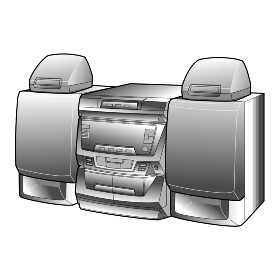
Illustration: CD-C410W,CP-C410
Illustration: CD-C415W,CP-C415
Illustration: CD-C420W,CP-C410,CP-SR410
SPECIFICATIONS ............................................................................................................................................................. 2
AC POWER SUPPLY CORD AND PLUG ......................................................................................................................... 2
VOLTAGE SELECTION ..................................................................................................................................................... 3
NAMES OF PARTS ........................................................................................................................................................... 3
OPERATION MANUAL ...................................................................................................................................................... 5
DISASSEMBLY .................................................................................................................................................................. 6
REMOVING AND REINSTALLING THE MAIN PARTS ..................................................................................................... 9
ADJUSTMENT .................................................................................................................................................................. 10
NOTES ON SCHEMATIC DIAGRAM ............................................................................................................................... 12
BLOCK DIAGRAM ............................................................................................................................................................ 13
SCHEMATIC DIAGRAM / WIRING SIDE OF P.W.BOARD .............................................................................................. 16
VOLTAGE ........................................................................................................................................................................ 30
WAVEFORMS OF CD CIRCUIT ....................................................................................................................................... 31
TROUBLESHOOTING (CD CHANGER CONTROL / CD SECTION) ............................................................................... 32
FUNCTION TABLE OF IC ................................................................................................................................................ 36
FL DISPLAY ...................................................................................................................................................................... 42
REPLACEMENT PARTS LIST/EXPLODED VIEW
All manuals and user guides at all-guides.com
CD-C410W/C415W/C420W,CP-C410/C415/SR410
SERVICE MANUAL
CONTENTS
SHARP CORPORATION
- 1 -
CD-C410W
CD-C415W
CD-C420W
CP-C410
CP-C415
CP-SR410
CD-C410W and CP-C410 constitute CD-C410W.
CD-C415W and CP-C415 constitute CD-C415W.
CD-C420W and CP-C410 and CP-SR410 constitute CD-
C420W.
• In the interests of user-safety the set should be restored to its
original condition and only parts identical to those specified be
used.
No. S6736CDC410W/
Page
Advertisement
Table of Contents

Related Manuals for Sharp CD-C410W


Summary of Contents for Sharp CD-C410W
-
Page 1: Table Of Contents
Illustration: CD-C410W,CP-C410 CP-C410 CP-C415 CP-SR410 Illustration: CD-C415W,CP-C415 CD-C410W and CP-C410 constitute CD-C410W. CD-C415W and CP-C415 constitute CD-C415W. CD-C420W and CP-C410 and CP-SR410 constitute CD- C420W. • In the interests of user-safety the set should be restored to its original condition and only parts identical to those specified be used. -
Page 2: Specifications
All manuals and user guides at all-guides.com CD-C410W/C415W/C420W,CP-C410/C415/SR410 FOR A COMPLETE DESCRIPTION OF THE OPERATION OF THIS UNIT, PLEASE REFER TO THE OPERATION MANUAL. SPECIFICATIONS CD-C410W/C415W/C420W CD-C410 General Front speaker section Frequency response: 100 mm (4") full-range speaker Power source:... -
Page 3: Voltage Selection
All manuals and user guides at all-guides.com CD-C410W/C415W/C420W,CP-C410/C415/SR410 VOLTAGE SELECTION Before operating the unit on mains, check the preset voltage. If the votage is different from your local voltage. Slide the AC power supply socket cover by slightly loosing the screw to the visible indication of the side of your local voltage. - Page 4 All manuals and user guides at all-guides.com CD-C410W/C415W/C420W,CP-C410/C415/SR410 CD-C420W Rear Panel 1. Speaker Terminals 2. AC Voltage Selector 3. AC Power Lead 4. Video/Auxiliary (Audio Signal) Input Sockets 5. Span Selector 6. FM 75 Ohms Aerial Terminal 7. Aerial Earth Terminal 8.
-
Page 5: Operation Manual
OPERATION MANUAL All manuals and user guides at all-guides.com – 5 –... -
Page 6: Disassembly
All manuals and user guides at all-guides.com CD-C410W/C415W/C420W,CP-C410/C415/SR410 DISASSEMBLY CD-C410W/CD-C415W/CD-C420W Caution on Disassembly Follow the below-mentioned notes when disassembling Illustaration: CD-C410W/CD-C415W the unit and reassembling it, to keep it safe and ensure Top Cabinet ( A1 ) x2 excellent performance: ø3 x12mm 1. - Page 7 All manuals and user guides at all-guides.com CD-C410W/C415W/C420W,CP-C410/C415/SR410 ( E1 ) x2 ( K1 ) x4 Switch PWB ø3 x10mm ø3 x14mm ( E1 ) x9 ( L1 ) x1 Front Panel ø3 x10mm ø2.6 x10mm Display ( E1 ) x1 Shift Lever ø3 x10mm...
- Page 8 All manuals and user guides at all-guides.com CD-C410W/C415W/C420W,CP-C410/C415/SR410 CP-SR410 CP-C415 Front Panel (C1) x1 Woofer Speaker Box Screw driver (B1)x2 Driver should be pried ø3x20mm away from speaker Box. (B1)x2 (B1)x2 ø3x20mm Direction of handle ø3x20mm Figure 8-2 Figure 8-1...
-
Page 9: Removing And Reinstalling The Main Parts
All manuals and user guides at all-guides.com CD-C410W/C415W/C420W,CP-C410/C415/SR410 REMOVING AND REINSTALLING THE MAIN PARTS CD MECHANISM SECTION Perform steps 1, 2, 3, 10 and 11 of the disassembly method Loading Motor to remove the CD mechanism. How to remove the loading motor (See Fig. -
Page 10: Adjustment
All manuals and user guides at all-guides.com CD-C410W/C415W/C420W,CP-C410/C415/SR410 ADJUSTMENT TUNER SECTION MECHANISM SECTION fL: Low-range frequency • Driving Force Check fH: High-renge frequency Torque Meter Specified Value • AM IF/RF Play: TW-2412 Tape 1: Over 80 g Signal generator: 400 Hz, 30%, AM modulated... - Page 11 All manuals and user guides at all-guides.com CD-C410W/C415W/C420W,CP-C410/C415/SR410 TEST MODE • Setting the test mode Any one of test mode can be set by pressing several keys as follows. <REC. PAUSE> + <DISC. SKIP> + <POWER> TEST: CD operation test •...
-
Page 12: Notes On Schematic Diagram
All manuals and user guides at all-guides.com CD-C410W/C415W/C420W,CP-C410/C415/SR410 NOTES ON SCHEMATIC DIAGRAM • The indicated voltage in each section is the one measured by • Resistor: Digital Multimeter between such a section and the chassis To differentiate the units of resistors, such symbol as K and with no signal given. -
Page 13: Block Diagram
All manuals and user guides at all-guides.com CD-C410W/C415W/C420W,CP-C410/C415/SR410 Figure 13 BLOCK DIAGRAM (1/3) – 13 –... - Page 14 All manuals and user guides at all-guides.com CD-C410W/C415W/C420W,CP-C410/C415/SR410 FM/AM ANTENNA TERMINAL FE301 AM IF S0008AW Q301 CF302 T351 FM FRONT END MONO/ FM IF IN IC303 VR351 L-CH LA1832 FM MUTE LEVEL R-CH FM/AM IF MUTIN FM OSC VOLTAGE REGURATER...
- Page 15 All manuals and user guides at all-guides.com CD-C410W/C415W/C420W,CP-C410/C415/SR410 UNSWITCH FL701 DISPLAY MEMORY BACK UP MONO/ST 31 32 TO CD SECTION TO CD SECTION Q701 TO POWER SECTION L-CH R-CH PHM1 MUTING Q353 Q354 SW701 AVDD SW725 IC701 AVREF IX0191AW XL702 SYSTEM CONTROL 4.19MHz...
-
Page 16: Schematic Diagram / Wiring Side Of P.w.board
All manuals and user guides at all-guides.com CD-C410W/C415W/C420W,CP-C410/C415/SR410 COLOR TABLE BROWN RD(R) P19 7-H ORANGE TO SENSOR PWB YELLOW CNS10 GREEN BLUE VIOLET GRAY SW717 POWER 10 9 8 7 6 5 4 3 2 1 SW718 WH(W) WHITE 10 15... - Page 17 All manuals and user guides at all-guides.com CD-C410W/C415W/C420W,CP-C410/C415/SR410 P18 5-H P19 9-C P19 9-D P18 5-D P18 4-D TO CD MOTOR PWB TO PICKUP UNIT TO PICKUP UNIT TO TUNER PWB TO TUNER PWB CNS3A CNS2A CNS1A CNP201 CNP303 MAIN PWB-A1...
- Page 18 All manuals and user guides at all-guides.com CD-C410W/C415W/C420W,CP-C410/C415/SR410 P16 1-B TO DISPLAY PWB PICKUP UNIT CNSM1 CNS1B 1 2 3 4 5 1 2 3 4 5 6 7 8 CNS2B 1 2 3 4 5 1 2 3 4 5 6 7 8...
- Page 19 All manuals and user guides at all-guides.com CD-C410W/C415W/C420W,CP-C410/C415/SR410 TUNER PWB-B1 POWER PWB-C 415W ONLY F963 T1.6A L 250V C220 C240 CNS901 C224 R210 F962 T2.5A L 250V R217 C223 TO MAIN PWB R212 R234 CNP901 R216 P17 11-G R215 T961...
- Page 20 All manuals and user guides at all-guides.com CD-C410W/C415W/C420W,CP-C410/C415/SR410 47/10 KTA1266 GR 0.47/50 1.5V 0.01 0.01 1/50 3.3V 64 63 61 60 55 54 53 52 51 50 49 CNS1B CNS1A CNP1 – FIN2 – – FIN1 EFBAL – – –...
- Page 21 All manuals and user guides at all-guides.com CD-C410W/C415W/C420W,CP-C410/C415/SR410 MAIN PWB-A1 (1/3) 0.01 64 63 62 61 60 59 58 57 56 55 54 53 52 51 50 EFLG µ-COM SUB-CODE SBSY INTERFACE DEF1 XVSS 3.3M X-TAL XOUT 2KX8 GENERATOR 0.047...
- Page 22 All manuals and user guides at all-guides.com CD-C410W/C415W/C420W,CP-C410/C415/SR410 CD_R R412 A_GND C410 CD_L 0.047 R480 (ML) R422 100K C434 0.0027 C436 R420 C406 RVref 22/16 TUN_R 0.047 RINVIN2 C438 C445 TUN_L (ML) R418 100P RTOUT 0.022 C440 RVRIN 10/16 R416...
- Page 23 All manuals and user guides at all-guides.com CD-C410W/C415W/C420W,CP-C410/C415/SR410 R477 OUT_R MAIN_L TO POWER PWB A_GND P26 1-B MAIN_R R478 415W ONLY C218 R480 CNP401 2.2/50 100K C434 OUT_R 0.0027 IN_R C436 P29 9-A 22/16 A-GND CNP201 C438 C445 IN_L 100P TO TUNER PWB 0.022...
- Page 24 All manuals and user guides at all-guides.com CD-C410W/C415W/C420W,CP-C410/C415/SR410 C702 220/6.3 FL701 Q701 KRC107 M R734 R751 R701 100K 100K R750 100K R738 KEY-3 R739 KEY-2 R740 KEY-1 R797 SET UP AVDD AVREF IC701 SRS ON/OFF 410W/415W: IX0174AW 420W:IX0191AW VLOAD SYSTEM...
- Page 25 All manuals and user guides at all-guides.com CD-C410W/C415W/C420W,CP-C410/C415/SR410 DISPLAY PWB-A2 SPAN SELECTOR R396 SW301 50kHz/9kHz SPAN R741 R734 100kHz/10kHz R397 R749 R751 R757 100K 100K R763 R767 R773 R777 R782 R756 1.2K 1.8K 2.2K 3.9K R750 100K 100K SW701 SW702...
- Page 26 All manuals and user guides at all-guides.com CD-C410W/C415W/C420W,CP-C410/C415/SR410 MAIN PWB-A1(3/3) – – IC801 LA4551 POWER AMP. C829 C855 47/50 560P TO CD C809 1000/25 MAIN_L C805 C810 1000/25 1/50 MAIN_R C812 C806 1/50 (ML) C814 (ML) R807 11.8V 19.3V Q941 2SD2012 Y 12.42V...
- Page 27 All manuals and user guides at all-guides.com CD-C410W/C415W/C420W,CP-C410/C415/SR410 L_CHECK R_CHECK C453 C454 1/50 1/50 C855 560P TO CD GND JK801 R835 HEADPHONES (1/2W) R836 (1/2W) HEADPHONES PWB-A3 FM SIGNAL C871 0.001 SO801 SP_L-CH – SP_L-CH_GND FRONT SPEAKER TERMINAL – SP_R-CH_GND...
- Page 28 All manuals and user guides at all-guides.com CD-C410W/C415W/C420W,CP-C410/C415/SR410 • NOTES ON SCHEMATIC DIAGRAM can be found on page 12. Figure 28 SCHEMATIC DIAGRAM (9/10) – 28 –...
- Page 29 All manuals and user guides at all-guides.com CD-C410W/C415W/C420W,CP-C410/C415/SR410 Figure 29 SCHEMATIC DIAGRAM (10/10) – 29 –...
-
Page 30: Voltage
All manuals and user guides at all-guides.com CD-C410W/C415W/C420W,CP-C410/C415/SR410 VOLTAGE IC401 IC701 IC303 IC101 NO. VOLTAGE NO. VOLTAGE NO. VOLTAGE NO. VOLTAGE NO. VOLTAGE NO. VOLTAGE NO. VOLTAGE VOLTAGE –24.7V 0.41V 2.13V(2.14V) –24.7V 4.6V(5V) 2.1V –24.7V 0.6V 2.1V(2.1V) 2.1V –24.7V 4.4V 2.1V(2.1V) -
Page 31: Waveforms Of Cd Circuit
All manuals and user guides at all-guides.com CD-C410W/C415W/C420W,CP-C410/C415/SR410 WAVEFORMS OF CD CIRCUIT STOP PLAY FOCUS SERCH 0.5ms 0.50 V 10.0 V IC1 20 F.E 0.5ms 10.0 V 0.5ms 5.0 V 0.50 V IC1 54 DRF 0.5ms 1.00 V PLAY 0.5ms 1.00 V... -
Page 32: Troubleshooting (Cd Changer Control / Cd Section)
All manuals and user guides at all-guides.com CD-C410W/C415W/C420W,CP-C410/C415/SR410 TROUBLESHOOTING (CD SECTION) When the CD does not function When the CD section does not operate When the objective lens of the optical pickup is dirty,this section may not operate.Clean the objective lens,and check the playback operation.When this section does not operate even after the above step is taken,check the following items. - Page 33 All manuals and user guides at all-guides.com CD-C410W/C415W/C420W,CP-C410/C415/SR410 • When the CD tray fails to open or close. Check the OPEN CLOSE SW and the wiring from the IC701 Is there following voltage input in specific state of IC701 pin 19? pin 19 to the OPEN CLOSE SW.
- Page 34 All manuals and user guides at all-guides.com CD-C410W/C415W/C420W,CP-C410/C415/SR410 • Playback can only be performed when a disc is loaded. Check the laser diode driver. Is the Focus servo active? (Can you hear it working?) Check the area around IC1(16) - (21) (focus servo circuit).
- Page 35 All manuals and user guides at all-guides.com CD-C410W/C415W/C420W,CP-C410/C415/SR410 • Checking the spin system. Play operation is performed without disc. The turntable rotates a little. The spin driver circuit is normal. Check the periphery of IC1 pins 23 to 27, pin 39, and pin 40, IC2 The turntable fails to rotate or rotates at high speed.
-
Page 36: Function Table Of Ic
All manuals and user guides at all-guides.com CD-C410W/C415W/C420W,CP-C410/C415/SR410 FUNCTION TABLE OF IC IC2 VHiLC78622U-1:Servo/Signal Control(LC78622U) (1/2) Terminal Name Input/Output Pin No. Function DEFI Input Input terminal of defect detection signal (DEF). (Connected to OV when not used.) Input For PLL Input terminal for test. - Page 37 All manuals and user guides at all-guides.com CD-C410W/C415W/C420W,CP-C410/C415/SR410 IC2 VHiLC78622U-1:Servo/Signal Control(LC78622U) (2/2) Terminal Name Input/Output Pin No. Function Output Output terminal of subcodes P, A, R, S, T, U and W. SFSY Output Output terminal of synchronous signal of subcode frame. It drops when subcode stands by.
- Page 38 All manuals and user guides at all-guides.com CD-C410W/C415W/C420W,CP-C410/C415/SR410 IC1 VHiLA9240M/-1:Servo Amp.,(LA9240M) (1/2) Function Port Name Pin No. FIN2 Connection pin for photodiode of pickup. RF signal is generated through addition with FIN pin, and FE signal is generated through subtraction.
- Page 39 All manuals and user guides at all-guides.com CD-C410W/C415W/C420W,CP-C410/C415/SR410 IC1 VHiLA9240M/-1:Servo Amp.,(LA9240M) (2/2) Function Port Name Pin No. Micro computer command clock input pin. Micro computer command data input pin. Micro computer command chip enable input pin. (DETECT RF) RF level detection output.
- Page 40 All manuals and user guides at all-guides.com CD-C410W/C415W/C420W,CP-C410/C415/SR410 IC701 RH-iX0191AWZZ:System Microcomputer (IX0191AW) (1/2) Function Pin No. Port Name Terminal Name Input/Output FIP6-0 FL DRIVER Output Segment Output — Connect with BACK UP VDD TAPE BIAS Output TAPE BIAS ON: H...
- Page 41 All manuals and user guides at all-guides.com CD-C410W/C415W/C420W,CP-C410/C415/SR410 IC701 RH-iX0191AWZZ:System Microcomputer (IX0191AW) (2/2) Terminal Name Pin No. Port Name Input/Output Function P124 TAPE1 RUN PULSE Input TAPE1 Run pluse P123 TAPE MECHA STOP Input Tape mecha up state: L 58-60...
-
Page 42: Fl Display
All manuals and user guides at all-guides.com CD-C410W/C415W/C420W,CP-C410/C415/SR410 IC5 VHiM56748FP-1:Focus/Tracking/Spin Slide Driver (M56748FP) Stand Vrel-in Standby SS.GND Vrel-out Standby Gain4 Gain1 Vctl4(-) Vctl(-) VM4(-) VM1(-) VM1(+) VM4(+) VM2(+) VM3(+) VM2(-) VM3(-) Vctl3(out) Vctl2(-) Gain2 Vctl3(-) Vctl3(+) Reg5V Regbase 10.8K 3.6K... - Page 43 “HOW TO ORDER REPLACEMENT PARTS” To have your order filled promptly and correctly, please furnish the For U.S.A. only following information. Contact your nearest SHARP Parts Distributor to order. 1. MODEL NUMBER 2. REF. No. 3. PART NO. 4. DESCRIPTION For location of SHARP Parts Distributor, Please call Toll-Free;...
- Page 44 All manuals and user guides at all-guides.com CD-C410W/C415W/C420W,CP-C410/C415/SR410 PRICE PRICE PART CODE DESCRIPTION PARTS CODE DESCRIPTION RANK RANK ZD971 VHEMTZJ300B-1 AB Zener,30V,MTZJ30B CD-C410W/CD-C415W/CD-C420W ZD972 VHEMTZJ6R2A-1 AA Zener,6.2V,MTZJ6.2A INTEGRATED CIRCUITS FILTERS VHILA9240M/-1 AV Servo Amp.,LA9240M BF351 RFILA0009AWZZ AE AM IF VHILC78622U-1...
- Page 45 All manuals and user guides at all-guides.com CD-C410W/C415W/C420W,CP-C410/C415/SR410 PRICE PRICE DESCRIPTION PARTS CODE DESCRIPTION PART CODE RANK RANK AB 10 µF,16V,Electrolytic C67,68 RC-GZA106AF1C C390 VCKYMN1HB471K J AA 470 pF,50V AB 47 µF,16V,Electrolytic C69,70 VCKYMN1HB221K J AA 220 pF,50V C391 RC-GZA476AF1C AB 220 µF,10V,Electrolytic...
- Page 46 All manuals and user guides at all-guides.com CD-C410W/C415W/C420W,CP-C410/C415/SR410 PRICE PRICE PART CODE DESCRIPTION PARTS CODE DESCRIPTION RANK RANK VRD-MN2BD101J AA 100 ohm,1/8W R162 VRD-MN2BD472J AA 4.7 kohms,1/8W VRD-MN2BD102J AA 1 kohm,1/8W R164 VRD-MN2BD472J AA 4.7 kohms,1/8W VRD-MN2BD123J AA 12 kohms,1/8W...
- Page 47 All manuals and user guides at all-guides.com CD-C410W/C415W/C420W,CP-C410/C415/SR410 PRICE PRICE DESCRIPTION PARTS CODE DESCRIPTION PART CODE RANK RANK R708,709 VRD-MN2BD102J AA 1 kohm,1/8W CNP10 92LCONEAP53254 J AD Plug,10Pin R711 VRD-MN2BD103J AA 10 kohm,1/8W CNP101 QCNCM742CAFZZ J AA Plug,3Pin R712~725 VRD-MN2BD102J...
- Page 48 All manuals and user guides at all-guides.com CD-C410W/C415W/C420W,CP-C410/C415/SR410 PRICE PRICE PART CODE DESCRIPTION PARTS CODE DESCRIPTION RANK RANK NFLYC0002AWZZ AG Flywheel Ass’y [Tape 1] CABINET PARTS NFLYC0003AWZZ AH Flywheel Ass’y [Tape 2] MLEVP0024AW01 AH Lever,FF/REW Roller Ass’y NGERH0027AWZZ J AE Gear,Cam 92LCAB2533AS1 AX Front Panel Ass’y [410W]...
- Page 49 All manuals and user guides at all-guides.com CD-C410W/C415W/C420W,CP-C410/C415/SR410 PRICE PRICE DESCRIPTION PARTS CODE DESCRIPTION PART CODE RANK RANK 248- 3 92LSUPT1749D AA Bracket,Magnet PWB-D QPWBF0106AWZZ J AF Tape Mechanism (PWB Only) NTNT-0018AWSA AK Turntable PWB-E QPWBF0027AWZZ J AD CD Motor (PWB Only)
- Page 50 All manuals and user guides at all-guides.com CD-C410W/C415W/C420W,CP-C410/C415/SR410 CD-C410W/CD-C415W/CD-C420W 306-2 306-1 306-3 305x2 PWB-E Figure 7 CD MECHANISM EXPLODED VIEW – 7 – – 50 –...
- Page 51 All manuals and user guides at all-guides.com CD-C410W/C415W/C420W,CP-C410/C415/SR410 CD-C410W/CD-C415W/CD-C420W TAPE1 TAPE2 503x3 503x2 503x3 503x2 SOLM2 SWM5 501x2 SWM4 SWM3 502x2 PWB-D BELT CONNECTION MOTOR Figure 8 TAPE MECHANISM EXPLODED VIEW – 51 – – 8 –...
- Page 52 All manuals and user guides at all-guides.com CD-C410W/C415W/C420W,CP-C410/C415/SR410 CD-C410W/CD-C415W/CD-C420W CD-C410W/ C420W Taiwan Only 619x6 CD-C420W 618x2 PWB-A1 601x9 209-1 606x2 PWB-A2 CD-C410W/ 601x2 602 618x2 C415W 209-2 FL701 PWB-A3 PWB-A4 PWB-B 201-4 616x3 Silicon 201-3 201-1 616x2 Grease 616x2 601x6...
- Page 53 All manuals and user guides at all-guides.com CD-C410W/C415W/C420W,CP-C410/C415/SR410 CD-C410W/CD-C415W/CD-C420W 608x2 608x2 243x2 MECHANISM 609x2 612x4 PWB-D SOLM1 Figure 10 CABINET EXPLODED VIEW (2/2) – 53 – – 10 –...
- Page 54 All manuals and user guides at all-guides.com CD-C410W/C415W/C420W,CP-C410/C415/SR410 CP-C410 SP1,2 708x4 Woofer Black WOOFER SP1 (L-CH) SP2 (R-CH) Figure 11 SPEAKER EXPLODED VIEW (1/3) – 54 – – 11 –...
- Page 55 All manuals and user guides at all-guides.com CD-C410W/C415W/C420W,CP-C410/C415/SR410 CP-SR410 SP1,2 WOOFER SP1 (L-CH) SP2 (R-CH) WOOFER WHITE LINE 704x3 704x3 Figure 12 SPEAKER EXPLODED VIEW (2/3) – 12 – – 55 –...
- Page 56 SP2 (R-CH) WOOFER WOOFER SP3 (L-CH) SP4 (R-CH) Figure 13 SPEAKER EXPLODED VIEW (3/3) A9706-2630NS•HA•M Printed in Japan Writer and Editor: Quality & Reliability Control Center of Communication & Audio Systems Group, Sharp Corp. EX•SA•SZ – 56 – – 13 –...
Need help?
Do you have a question about the CD-C410W and is the answer not in the manual?
Questions and answers