Table of Contents
Advertisement
Quick Links
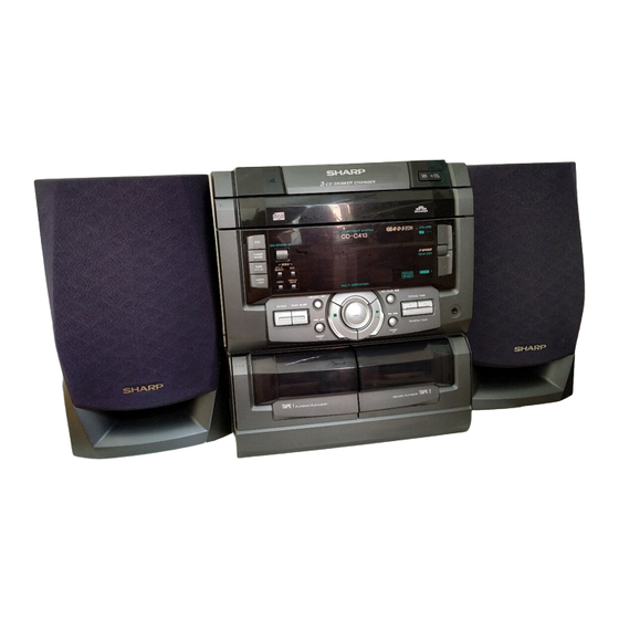
This new model CD-C413H has almost the same structure as
the former models CD-C411H except for some outer parts,
the speaker Box has been changed, and so only these parts
are here described. When servicing the CD-C413H, please
refer to the already issued service manual for CD-C411H
(S5834CDC421H/) as well as this service manual.
DIFFERENCE BETWEEN CD-C411H AND CD-C413H
REF.
PART NO.
NO.
CD-C411H
CABINET PARTS
201
92LCAB2829AS1
206
GCAB-1050AWSB
207
GCOVA1186AWSB
208
GCOVA1187AWSB
209
GCOVA1215AWSA
210
GDORF0054AWSB
211
GDORF0055AWSB
212
GITAR0356AWSA
212
GITAR0357AWSA
212
GITAR0415AWSA
212
213
GITAS0050AWSB
214
GITAS0051AWSB
218
HDECQ0366AWSA
219
JKNBZ0516AWSB
220
JKNBZ0517AWSB
ACCESSORIES / PACKING PARTS
5
TLABE0230AWZZ
MARK: SPARE PARTS-DELIVERY SECTION
SERVICE MANUAL
PART NO.
CD-C413H
J
92LCAB2947AS1
J
GCAB-1050AWSC
J
GCOVA1186AWSC
J
GCOVA1187AWSC
J
GCOVA1208AWSA
J
GDORF0054AWSD
J
GDORF0055AWSD
J
J
J
GITAR0391AWSA
J
GITAS0050AWSC
J
GITAS0051AWSC
J
HDECQ0389AWSA
J
JKNBZ0516AWSC
J
JKNBZ0517AWSC
J
TLABE0259AWZZ
SHARP CORPORATION
– 1 –
CD-C413H
CD-C413H mini component system consisting of
CD-C413H mini component system and CP-C413H
speaker system.
• In the interests of user-safety the set should be restored to its
original condition and only parts identical to those specified be
used.
NOTE FOR USERS IN THE U.K.
• Recording and playback of any material may require consent,
which SHARP is unable to give. Please refer particularly to the
provisions of the Copyright Act 1956, the Dramatic and Musical
Performers Protection Act 1958, the Performers Protection Acts
1963 and 1972 and to any subsequent statutory enactments and
orders.
DESCRIPTION
J
Front Panel A'ssy.
J
Top Cabinet
J
Cover,CD Tray Panel,Left
J
Cover,CD Tray Panel,Right
J
Cover,CD Tray
J
Cassette Holder,TAPE 1
J
Cassette Holder,TAPE 2
Back Board,[For U.K.]
Back Board,[For Germany]
Back Board,[For Russia]
J
Back Board
J
Side Panel,Left
J
Side Panel,Right
J
Display Panel
J
Button,Function
J
Button,[X-BASS]
J
Label, Bar Code
This document has been published to be used
for after sales service only.
The contents are subject to change without notice.
CD-C413H
No. S7853CDC413H/
CODE
BD
AQ
AF
AF
AF
AL
AL
––
––
––
AH
AH
AH
AH
AG
AF
AB
Advertisement
Table of Contents

Subscribe to Our Youtube Channel
Related Manuals for Sharp CD-C413H


Summary of Contents for Sharp CD-C413H
- Page 1 NOTE FOR USERS IN THE U.K. This new model CD-C413H has almost the same structure as • Recording and playback of any material may require consent, the former models CD-C411H except for some outer parts, which SHARP is unable to give.
- Page 2 SP1 (L-CH) SP2 (R-CH) SP1 (L-CH) SP2 (R-CH) SPEAKER EXPLODED VIEW COPYRIGHT 1998 BY SHARP COPORATION SHARP CORPORATION ALL RIGHTS RESERVED. Communication Systems Group Quality & Reliability Control Center No part of this publication may be reproduced, Higashihiroshima, Hiroshima 739-0192, Japan...
-
Page 3: Table Of Contents
FL DISPLAY ..................................50 REPLACEMENT PARTS LIST/EXPLODED VIEW PACKING OF THE SET (For U.K. Only) This document has been published to be used SHARP CORPORATION for after sales service only. – 1 – The contents are subject to change without notice. -
Page 4: Important Service Notes (For U.k. Only)
CD-C421H / C411H SAFETY PRECAUTION FOR (FOR GERMANY) SERVICE MANUAL Precaution to be taken when replacing and servicing the Laser Pickup. The AEL (Accessible Emission Level) of Laser Power Output for this model is specified to be lower than Class I Requirements. However, the following precautions must be observed during LASER KLASSE 1 (Illustration:CD-C421H) -
Page 5: Specifications
CD-C421H / C411H FOR A COMPLETE DESCRIPTION OF THE OPERATION OF THIS UNIT, PLEASE REFER TO THE OPERATION MANUAL. SPECIFICATIONS CD-C421H Cassette deck section General Frequency Power source: AC 230 V, 50 Hz response: 50-14,000 Hz (Normal tape) Power consumption: 47 W Signal/noise ratio: 55 dB (TAPE 1, playback) -
Page 6: Names Of Parts
CD-C421H / C411H NAMES OF PARTS CD-C421H/C411H Front Panel 1. Disc Tray 2. Disc Skip Button 3. Open/Close Button: 4. CD Play Indicator: 5. CD Repeat Indicator: 8 9 10 11 6. CD Pause Indicator: 4 5 6 7. Disc Number Indicators 8. - Page 7 CD-C421H / C411H Speaker Section CP-C421H Front Speaker CP-C421H 6. Tweeter 7. Woofer 8. Bass Reflex Duct 9. Speaker Wire CP-C411H 6. Full-Range Speaker 7. Bass Reflex Duct 8. Speaker Wire CP-C411H Surround Speaker [CD-C421H Only] GBOXS00018AWZZ 10. Full-Range Speaker 11.
-
Page 8: Operation Manual
CD-C421H / C411H OPERATION MANUAL – 6 –... -
Page 9: Disassembly
CD-C421H / C411H DISASSEMBLY Caution on Disassembly CD-C421H/C411H Follow the below-mentioned notes when disassembling Top Cabinet the unit and reassembling it, to keep it safe and ensure ( A1 ) x2 excellent performance: ø3 x12mm 1. Take cassette tape and compact disc out of the unit. 2. - Page 10 CD-C421H / C411H ( F1 ) x2 ø3 x10mm ( J1 ) x1 Switch PWB ø3 x10mm ( F1 ) x3 Front Panel ø3 x10mm ( F1 ) x1 ( J2 ) x1 Display ø3 x 8mm Washer Turntable Main PWB ( E2 ) x1 ( F3 ) x2 Tuner PWB...
-
Page 11: Removing And Reinstalling The Main Parts
CD-C421H / C411H CP-C421H CP-C411H REMOVAL PROCEDURE FIGURE STEP PROCEDURE STEP REMOVAL FIGURE Front Speaker 1. Net Frame ....(A1) x1 Front Speaker 1. Net Frame ....(A1) x1 3. Duct Panel ..... (A2) x1 3. Duct Panel ..... (A2) x1 3. -
Page 12: Adjustment
CD-C421H / C411H ADJUSTMENT TUNER SECTION MECHANISM SECTION • Driving Force Check fL: Low-range frequency fH: High-renge frequency Torque Meter Specified Value • AM IF/RF Play: TW-2412 Tape 1: Over 80 g Signal generator: 400 Hz, 30%, AM modulated Tape 2: Over 80 g Frequency Test Stage Frequency Setting/... - Page 13 CD-C421H / C411H TEST MODE • Setting the test mode Any one of test mode can be set by pressing several keys as follows. <REC. PAUSE> + <CD> + <POWER> TEST: CD operation test • TEST mode Function — CD test mode Setting of TEST mode Indication of CD TST mode (Fig.
- Page 14 CD-C421H / C411H RDS (Radio Data System) OPERATION DISPLAY MODE Figure 12-1 Receiving FM Stations with RDS (Radio Data Descriptions of the PTY (Programme Type) codes, TP (Traffic System) Programme) and TA (Traffic Announcement) Eith the CD-C421H/C411H, you can search for and receive RDS is a broadcasting service which a growing number of FM the forrowing PTY, TP and TA signals.
- Page 15 CD-C421H / C411H – 13 –...
- Page 16 CD-C421H / C411H • ASPM SCAN: 87.50MHz → 108.00 MHz. • Only RDS signal is memorized by ASPM because RDS signal has PI code and is suitable and convenient for ASPM operation. ASPM Comparing field strength, only one strongest RDS station is memorized of all stations (repeater relay stations) that have same PI code.
- Page 17 CD-C421H / C411H EON summary notice for reference 1. EON-TI/PTY EON stand-by can be set, only when EON ind. lights up. While EON ind. goes out (NO EON STATION), EON stand-by can't be set. If the EON button is pressed, then “NO EON” is indication the display. 2.
-
Page 18: Notes On Schematic Diagram
CD-C421H / C411H NOTES ON SCHEMATIC DIAGRAM • The indicated voltage in each section is the one measured • Resistor: by Digital Multimeter between such a section and the chas- To differentiate the units of resistors, such symbol as K and sis with no signal given. -
Page 19: Block Diagram
CD-C421H / C411H Figure 17 BLOCK DIAGRAM (1/3) – 17 –... - Page 20 CD-C421H / C411H SO301 FM IF ANTENNA CF351 X351 AMP. FL701 TERMINAL FM IF FM IF FM FRONT END QT21 CF301 Q301 CF302 AM IF FE301 LOW PASS FM IF IN T351 FILTER L354 (AC) FM/AM ANTENNA IC303 VR351 FM IF DET/FM MPX/AM IF LA1832 FM MUTE LEVEL AM OSC...
- Page 21 CD-C421H / C411H FL701 8 6 5 SW725,726 –VP Q701 19 21 22 (AC) KEY5 KEY MATRIX –VP SW701~SW724 KEY1 IC701 IX0223AW SYSTEM MICROCOMPUTER RESET Q702 SYS STOP XL701 Q703 24 20 52 40 14 15 16 17 18 Q704 ZD701 CD RES CD SL–...
-
Page 22: Waveforms Of Cd Circuit
CD-C421H / C411H WAVEFORMS OF CD CIRCUIT STOP PLAY FOCUS SERCH 0.5ms 0.50 V 10.0 V IC1 20 F.E 0.5ms 10.0 V 0.5ms 5.0 V 0.50 V IC1 54 DRF 0.5ms 1.00 V PLAY 0.5ms NORMAL DISC 1.00 V TN0=01 20ms 1.00 V 0.5ms... -
Page 23: Schematic Diagram / Wiring Side Of P.w.board
CD-C421H / C411H DISPULAY PWB-A2 SW721 SW714 VOLUME VOLUME DOWN SW722 X-BASS/ EQUALIZER FW703 SW713 TO MAIN PWB TUNING UP P22 4-A /TIME C719 SW715 R790 RANDOM/ DEMO RX701 C718 R795 R751 ZD701 R769 R738 SW720 TUNING DOWN R770 /TIME Q703 Q704 C711... - Page 24 CD-C421H / C411H TO DISPLAY PWB P21 2-B CNPM1 TO TAPE MECHANISM PWB FW703 P24 5-D CNS703 R569 R511 R514 Q571 Q511 R568 CNSM1 Q514 R583 R570 Q583 C571 C570 C511 Q513 Q582 C584 C572 R512 R513 L501 C609 R584 C512 Q581 R628...
- Page 25 CD-C421H / C411H TO DISPLAY PWB P21 2-F MAIN PWB-A1 FW702 CNS702 IC91 CNS10 TO CD MECHANISM P25 8-E CNS601 D601 R630 R644 R638 C608 CNS2A R629 R602 TO CD MECHANISM R631 P25 8-C R642 R623 R639 R643 R640 R641 R636 R601 R635...
- Page 26 CD-C421H / C411H When Servicing, pay attention as the area enclosed by this line ) is directly connected with AC main voltage. POWER PWB-B D903 PT901 POWER TRANSFORMER D901 L901 CORE MAIN PWB D905 P22 3-F D907 CNP901 C910 TF901 ZD901 S0901 AC POWER...
- Page 27 CD-C421H / C411H PICKUP UNIT(306) CNS1A CNS1B TO MAIN PWB P23 12-E CNP1 TO MAIN PWB P23 12-C CNP2 CNS2A CNS2B CNS5 MECHA UP DISC NUMBER SENSOR PWB-E OPEN/CLOSE T/T UP/DOWN LOADING CNS10 TO MAIN PWB P23 12-B SOLENOID SOLM2 CNP10 CD MOTOR PWB-F SLED MOTOR...
- Page 28 CD-C421H / C411H TUNER PWB-C CT23 RT30 RT29 RT32 RT37 RT28 RT33 RT36 RT34 RT35 R366 CT37 E C B XT21 Q354 CT26 Q353 R377 E C B LT22 R361 C371 CNS303 C374 C373 R370 X351 C368 R357 TO MAIN PWB C369 P23 12-C R356...
- Page 29 CD-C421H / C411H IC501 IC303 IC401 IC701 NO. VOLTAGE NO. VOLTAGE NO. VOLTAGE NO. VOLTAGE NO. VOLTAGE NO. VOLTAGE NO. VOLTAGE NO. VOLTAGE –24.7V 2V(2V) 0.41V 2V(2V) –24.7V 2.1V 0.6V 7.2V(8.2V) –24.7V 2.1V 0.5V(0.8V) –24.7V 4.4V 1.8V 2V(2V) –24.7V 2.2V 1.3V 0V(0V) –24.7V...
- Page 30 CD-C421H / C411H TO TUNER PWB TO DISPLAY PWB P37 9-G P35 7-A FW702 CNS303 TO MAIN PWB(3/3) POWER AMP. TO MAIN PWB(3/3) SECTION POWER AMP.SECTION CNP303 P32 2-F P32 2-F 9 8 7 6 5 4 3 2 1 C602 150P +5.6V MAIN_SO...
- Page 31 CD-C421H / C411H TO TUNER PWB P37 9-G CNS303 TO MAIN PWB(2/3) CD SECTION P31 11-C CNP303 C412 R412 C456 390P 220P RIGHT R414 SO401 1.5K VIDEO/AUX R413 R418 1.5K LEFT C457 R411 C411 C402 220P 390P 0.047 R402 (ML) 38 39 C442 C404...
- Page 32 CD-C421H / C411H R1 1K 0.01 KTA1266 GR 47/16 0.33/50 1/50 0.47/50 – FIN2 – – FIN1 EFBAL – – – FOSTA – DGND TOSTA – 2FREQ 0.1/50 – LASER – 0.033 TE– – FSTA 100K LA9241M 8/12CM 0.001 SERVO AMP. SLOF –...
- Page 33 CD-C421H / C411H LC78622K SERVO/SIGNAL CONTROL 0.01 0.022 EFLG 16.93MHz U-COM SBSY SUB-CODE INTERFACE DEF1 XVSS 3.3M X-TAL XOUT GENERATOR 2KX8 0.022 0.047 VVSS XVDD ISET MUTER 0.022 RVDD 0.047 VCO CLOCK ERROR COERECT 2.7K 220P CD_R RCHO OSC CONTROL FLAG CONTROL 1BIT VVDD...
- Page 34 CD-C421H / C411H MAIN PWB-A1(3/3) IC961 – LA4451:411H LA4450:421H – POWER AMP. FM SIGNAL C975 1000/25 C963 1/50 MAIN_L TO MAIN PWB(1/3) A_GND C976 A.P.SECTION 1000/25 MAIN_R R975 P29 12-C C964 C968 (1/2W) 1/50 R972 0.001 C977 C972 C980 0.001 (ML) (ML) C978...
- Page 35 CD-C421H / C411H HEADPHONE PWB-A4 R982 330 (1/2W) JK961 HEADPHONES R975 R981 (1/2W) L963 R972 2.2mH (1/2W) L962 L961 421H ONLY C977 0.29µH 0.29µH (ML) C986 C989 0.022 0.022 R986 (ML) (ML) LUG962 C979 R983 2.2:411H (258) 2.2:411H 3.3:421H CHASSIS 3.3:421H (ML) C987...
- Page 36 CD-C421H / C411H TO MAIN FW702 FL701 FL DISPLAY 37 36 35 34 33 32 31 30 29 28 27 26 25 24 23 22 21 20 19 18 17 16 15 14 13 12 11 10 9 8 7 6 5 41 40 Q701 KRC107 M...
- Page 37 CD-C421H / C411H TO MAIN PWB(1/3) P28 5-B DISPLAY PWB-A3 R759 R760 FW701 SW725 SW726 OPEN DISC /CLOSE SKIP R701 R702 R703 1.2K R705 SW701 SW702 SW703 L702 R706 1.8K 0.82µH TIMER CLOCK R707 STAND-BY /SLEEP R709 R711 R712 R713 R714 R708 R710...
- Page 38 CD-C421H / C411H VD301-1 C343 AM ANT. KV1236Z23F L354 R319 C342 R358 0.022 100K 8.2K VR351 T302 10K(B) C332 C323 L353 C338 0.022 FM MUTE 0.022 LEVEL 0.001 FILT D303 R350 SHASSIS 1SS133 2.7K C367 1/50 D304 24 23 22 19 18 1SS133 IC30...
- Page 39 CD-C421H / C411H QT21 RT34 KTC3199 GR RT36 5.2V RT37 RT35 2.6V (0V) 220K 220K 220K (0V) (0V) RT26 RT30 RT28 R357 470K LT22 C373 L354 2.2µH CT28 0.033 R363 47/10 1.5K CT29 C371 0.022 1/50 MUTING 24 23 22 21 18 17 16 15 14 13 Q353 LOW PASS...
-
Page 40: Troubleshooting (Cd Changer Control / Cd Section)
CD-C421H / C411H TROUBLESHOOTING (CD SECTION) When the CD does not function When the CD section does not operate When the objective lens of the optical pickup is dirty,this section may not operate.Clean the objective lens,and check the playback operation.When this section does not operate even after the above step is taken,check the following items. - Page 41 CD-C421H / C411H • When the CD tray fails to open or close. Check the OPEN CLOSE SW and the wiring from the IC701 Is there following voltage input in specific state of IC701 pin 19? pin 19 to the OPEN CLOSE SW. Open state: 0V Close state: 0V Intermediate state between open state and close state: 4.3V...
- Page 42 CD-C421H / C411H • Playback can only be performed when a disc is loaded. Check the laser diode driver. Is the Focus servo active? (Can you hear it working?) Check the area around IC1(16) - (21) (focus servo circuit). If the disc is not turning, the DRF Does the DRF signal change from "L"...
- Page 43 CD-C421H / C411H • Checking the spin system. Play operation is performed without disc. The turntable rotates a little. The spin driver circuit is normal. Check the periphery of IC1 pins 23 to 27, pin 39, and pin 40, IC2 The turntable fails to rotate or rotates at high speed.
-
Page 44: Function Table Of Ic
CD-C421H / C411H FUNCTION TABLE OF IC IC2 VHiLC78622K-1:Servo/Signal Control(LC78622K) (1/2) Terminal Name Input/Output Function Pin No. DEFI Input Input terminal of defect detection signal (DEF). (Connected to OV when not used.) Input For PLL Input terminal for test. Pull-down resistor is integrated. Surely connected to 0V. Output Output terminal of phase comparison for external VCO control. - Page 45 CD-C421H / C411H VHiLC78622K-1:Servo/Signal Control(LC78622K) (2/2) Pin No. Terminal Name Input/Output Function Output Output terminal of subcodes P, A, R, S, T, U and W. SFSY Output Output terminal of synchronous signal of subcode frame. It drops when subcode stands by. SBCK Input Clock input terminal to read subcode.
- Page 46 CD-C421H / C411H IC1 VHiLA9241M/-1:Servo Amp.(LA9241M) (1/2) Function Port Name Pin No. FIN2 Connection pin for photodiode of pickup. RF signal is generated through addition with FIN pin, and FE signal is generated through subtraction. FIN1 Connection pin for photodiode of pickup. Connection pin for photodiode of pickup.
- Page 47 CD-C421H / C411H IC1 VHiLA9241M/-1:Servo Amp.(LA9241M) (2/2) Function Port Name Pin No. Micro computer command clock input pin. Micro computer command data input pin. Micro computer command chip enable input pin. (DETECT RF) RF level detection output. (Focus Serch Select) Pin to switch focus search mode. (± search/+ search for reference voltage) VCC2 VCC pin for servo system and digital system.
- Page 48 CD-C421H / C411H IC601 RH-iX0225AWZZ:Main System Microcomputer (IX0225AW) (1/2) Pin No. Port Name Terminal Name Input/Output Function Output Not used OUT:H OPEN T_RECPLY Output REC/P.B Selection Output Not used OUT:H OPEN Output CD Mute Contorol DSPRES Output Reset Output For CD Display SLM2 Output CD Slide Motor–...
- Page 49 CD-C421H / C411H IC601 RH-iX0225AWZZ:Main System Microcomputer (IX0225AW) (1/2) Pin No. Port Name Terminal Name Input/Output Function P115 Output Not used OUT:H OPEN P114 SRS_P Input SRS exsists or not exist 65*-66* P113-112 Output Not used OUT:H OPEN P111 Input TAPE2 A Side Proof Roof P110 Output...
- Page 50 CD-C421H / C411H IC701 RH-iX0223AWZZ:System Microcomputer (IX0223AW) (1/2) Pin No. Port Name Terminal Name Input/Output Function FIP6-0 G06-00 Output – — +Power Supply SCK0 C2B CLK Output C2B Serial Clock Output C2B DO Output C2B Serial Data Output C2B DI Input C2B Serial Data Input C2B CE...
- Page 51 CD-C421H / C411H 64 63 62 61 60 59 58 57 56 55 54 53 52 51 50 49 48 47 46 45 44 43 P33/ P113/ FIP21 P112/ P34/TI2 FIP20 P35/PCL P111/ LED CLK FIP19 P110/ P36/BUZ LED DATA FIP18 P107/ LED LCK...
-
Page 52: Fl Display
CD-C421H / C411H IC5 VHiM56748FP-1: Focus/Tracking/Spin/Slide Driver (M56748FP) Vref-in Stand Vref-in Standby Vref-out SS.GND Vref-out Standby Gain1 Gain4 Gain1 Gain4 Vctl1(–) Vctl4(–) VM1(–) VM4(–) VM1(–) VM4(–) VM1(+) VM4(+) VM1(+) VM4(+) VM2(+) VM3(+) VM2(+) VM3(+) VM2(–) VM3(–) VM2(–) VM3(–) Vctl2(–) Vctl3(out) Vctl3(out) Gain2 Vctl3(–) - Page 53 CD-C421H / C411H IC5 VHiM56748FP-1: Focus/Tracking/Spin/Slide Driver (M56748FP) Vref-in Stand Vref-in Standby Vref-out SS.GND Vref-out Standby Gain1 Gain4 Gain1 Gain4 Vctl1(–) Vctl4(–) VM1(–) VM4(–) VM1(–) VM4(–) VM1(+) VM4(+) VM1(+) VM4(+) VM2(+) VM3(+) VM2(+) VM3(+) VM2(–) VM3(–) VM2(–) VM3(–) Vctl2(–) Vctl3(out) Vctl3(out) Gain2 Vctl3(–)
Need help?
Do you have a question about the CD-C413H and is the answer not in the manual?
Questions and answers