Table of Contents
Advertisement
• SRS technology Licensed from SRS Labe. SRS technology holds
the follwing patents: U.S. Patent No. 4,748,669, U.S. Patent No.
4,841,572 and U.S. Patent No. 4,866,774.
• SRS the SRS Logo (
) and the SOUND RETRIEVAL SYSTEM
are registered trademarks of SRS Labs, Inc.
Safety Precaution For Service Manual .......................................................................................................... 2
Voltage Selection .................................................................................................................................................... 2
Ac Power Supply Cord And Ac Plug Adaptor ................................................................................................. 2
Specifications ............................................................................................................................................................ 3
Names Of Parts .......................................................................................................................................................... 4
Operation Manual ..................................................................................................................................................... 6
Disassembly ................................................................................................................................................................. 7
Removing And Reinstalling The Main Parts .................................................................................................... 9
Adjustment ................................................................................................................................................................ 10
Notes On Schematic Diagram ............................................................................................................................. 12
Block Diagram .......................................................................................................................................................... 13
Schematic Diagram / Wiring Side Of P.w.board ............................................................................................. 16
Waveforms Of Cd Circuit ..................................................................................................................................... 37
Troubleshooting (Cd Section) .......................................................................................................................... 38
Function Table Of Ic .............................................................................................................................................. 42
Fl Display ..................................................................................................................................................................... 51
REPLACEMENT PARTS LIST/EXPLODED VIEW
SERVICE MANUAL
CD-C440W AND CP-C440W constitute CD-C440W.
• In the interests of user-safety the set should be restored to its
CONTENTS
SHARP CORPORATION
– 1 –
CD-C440W/CP-C440W
CD-C440W
CP-C440W
original condition and only parts identical to those specified be
used.
No. S7749CDC440W/
Page
Advertisement
Table of Contents

Related Manuals for Sharp CD-C440W


Summary of Contents for Sharp CD-C440W
- Page 1 CD-C440W CP-C440W • SRS technology Licensed from SRS Labe. SRS technology holds CD-C440W AND CP-C440W constitute CD-C440W. the follwing patents: U.S. Patent No. 4,748,669, U.S. Patent No. 4,841,572 and U.S. Patent No. 4,866,774. • In the interests of user-safety the set should be restored to its •...
-
Page 2: Safety Precaution For Service Manual
CD-C440W/CP-C440W SAFETY PRECAUTION FOR SERVICE MANUAL Precaution to be taken when replacing and servicing the Laser Pickup. The AEL (Accessible Emission Level) of Laser Power Output for this model is specified to be lower than Class I Requirements. However, the following precautions must be observed during servicing to protect your eyes against exposure to the Laser beam. -
Page 3: Specifications
CD-C440W/CP-C440W FOR A COMPLETE DESCRIPTION OF THE OPERATION OF THIS UNIT, PLEASE REFER TO THE OPERATION MANUAL. SPECIFICATIONS CD-C440W Cassette deck section General Type: Compact cassette tape Power source: AC 110/127/220/230-240 V, 50/60 Hz Frequency response: 50 - 14,000 Hz (Normal tape) -
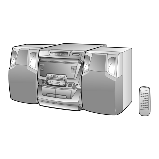
Page 4: Names Of Parts
CD-C440W/CP-C440W NAMES OF PARTS CD-C440W Front Panel 1. Disc Tray 2. Disc Number Selector Buttons 3. Disc Skip Button 4. Open/Close Button: 5. CD Play Indicator: 5 6 7 6. CD Repeat Indicator: 7. CD Pause Indicator: 8. Disc Number Indicators 9. - Page 5 CD-C440W/CP-C440W CD-C440W Rear Panel 1. Video/Auxiliary (Audio Signal) Input Sockets 2. Span Selector Switch 3. AC Voltage Selector 4. AC Power Lead 5. FM 75 ohms Aerial Terminal 6. Aerial Earth Terminal 7. AM Aerial Terminal 8. Speaker Terminals CP-C440W Speaker Section 9.
-
Page 6: Operation Manual
CD-C440W/CP-C440W OPERATION MANUAL – 6 –... -
Page 7: Disassembly
CD-C440W/CP-C440W DISASSEMBLY CD-C440W Caution on Disassembly Follow the below-mentioned notes when disassembling the unit and reassembling it, to keep it safe and ensure Top Cabinet ( A1 ) x2 excellent performance: ø3 x12mm 1. Take cassette tape and compact disc out of the unit. -
Page 8: Cp-C440W
CD-C440W/CP-C440W ( P1 ) x4 ( F3 ) x2 ø3 x12mm Headphone Front Panel ( Q1 ) x1 ( F4 ) x3 ( F2 ) x2 ø2.6 x10mm ( G1 ) x1 ø3 x11mm ( F3 ) x1 Shift Lever... -
Page 9: Removing And Reinstalling The Main Parts
CD-C440W/CP-C440W REMOVING AND REINSTALLING THE MAIN PARTS CD MECHANISM SECTION Perform steps 1, 2, 3, 14 and 15 of the disassembly method to remove the CD mechanism. Turntable Up/Down Motor How to remove the turntable up/down motor (See Fig. 9-1) 1. -
Page 10: Adjustment
CD-C440W/CP-C440W ADJUSTMENT TUNER SECTION MECHANISM SECTION fL: Low-range frequency • Driving Force Check fH: High-renge frequency Torque Meter Specified Value • AM IF/RF Play: TW-2412 Tape 1: Over 80 g Signal generator: 400 Hz, 30%, AM modulated Tape 2: Over 80 g... -
Page 11: Test Mode
CD-C440W/CP-C440W TEST MODE • Setting the test mode Any one of test mode can be set by pressing several keys as follows. <REC. PAUSE> + <CD> + <POWER> TEST: CD operation test • TEST mode Function — CD test mode Setting of TEST mode Indication of CD TST mode (Fig. -
Page 12: Notes On Schematic Diagram
CD-C440W/CP-C440W NOTES ON SCHEMATIC DIAGRAM • The indicated voltage in each section is the one measured • Resistor: by Digital Multimeter between such a section and the chas- To differentiate the units of resistors, such symbol as K and sis with no signal given. -
Page 13: Block Diagram
CD-C440W/CP-C440W Figure 13 BLOCK DIAGRAM (1/3) – 13 –... - Page 14 CD-C440W/CP-C440W FL701 CF351 X351 FM IF AM IF FE301 CF302 FM FRONT END 8 6 5 T351 FM IF IN FM/AM (AC) IC303 LA1832 VR351 FM MUTE LEVEL FM IF DET/FM MPX/AM IF SO301 ANTENNA TERMINAL FM OSC MUTING Q353...
- Page 15 CD-C440W/CP-C440W FL701 8 6 5 Q701 19 21 22 (AC) KEY MATRIX KEY5 SW701–SW712 SW717,SW719,SW721 SW723–SW726 SW728–SW740 KEY0 IC701I X0170AW MICROCOMPUTER DATA CLOCK IC702 LED701–LED711 BU2092F LED714–LED719 RESET Q704 SYS STOP Q705 14 15 16 17 18 Q706 ZD701 CD MUTE CD RES CD SL–...
- Page 16 CD-C440W/CP-C440W 47/16 0.01 KTA1266 GR 0.01 – FIN2 – – FIN1 EFBAL – – – – FOSTA DGND TOSTA – 2FREQ – 0.1/50 LASER – 0.033 TE– FSTA – 100K LA9240M 8/12CM SERVO AMP. SLOF – – 0.033 5.6K TESI RFS–...
- Page 17 CD-C440W/CP-C440W CD SIGNAL MAIN PWB-A1(1/3) 0.01 EFLG µ-COM SBSY SUB-CODE INTERFACE DEF1 XL10 XVSS 3.3M 0.033 X-TAL XOUT GENERATOR 2KX8 0.047 VVSS XVDD ISET MUTER TO MAIN KTC3199 GR SECTION ERROR 0.047 RVDD CLOCK COERECT P21 9-A CD_R-CH RCHO FLAG...
- Page 18 CD-C440W/CP-C440W P21 7-A WT502 TO MAIN PWB FW702 FL701 9 8 7 6 5 41 40 37 36 35 34 33 32 31 30 29 28 27 26 25 24 23 22 21 20 19 18 17 16 15 14 13 12 11 10...
- Page 19 CD-C440W/CP-C440W P21 7-A RD07 RD06 RD05 RD04 O MAIN PWB 5.6K 3.9K 2.2K SW708 SW707 SW706 SW705 SW704 OPEN DISK DISK 3 DISK 2 DISK 1 /CLOSE SKIP FW702 LED715 LED714 DISC 3 DISC 2 LED717 LED716 LED719 LED718 DISC 1...
- Page 20 CD-C440W/CP-C440W P18 5- TO DISPLA FW70 P23 12-D P17 7-H P23 12-C TO DECK SECTION TO CD SECTION TO DECK SECTION WT502 MAIN PWB-A1(2/3) D_GND CD_RWC R612 R680 CD_WRQ R611 CD_SQIN R610 CD_COOUT R609 CD_CQCK R608 CD_SL+ R607 CD_SL– R606...
- Page 21 CD-C440W/CP-C440W P27 10-G P18 5-A TO DISPLAY PWB TO TUNER PWB P17 12-C FW702 CNP303 TO CD SECTION P23 12-D P23 12-D TO DECK TO DECK SECTION SECTION WT502 CNP502 R561 L-CH C585 R563 1.8K 390P VIDEO/AUX 1 R564 C586 390P 1.8K...
- Page 22 CD-C440W/CP-C440W QM05 PLAYBACK SIGNAL KTA1266GR DRIVER RECORD SIGNAL RM11 RM12 2.2K RM02 DRIVER 6.8K QM01 KTA1266GR MOTOR DRIVER QM02 RM03 KTA1273Y TAPE MECHANISM PWB-F DRIVER QM03 TAPE RM07 FWM1 FWM2 KTA1271Y SPEED VRM1 MOT L MOT L 3.3K(B) 2.7K MOT H...
- Page 23 CD-C440W/CP-C440W MAIN PWB-B1(3/3) TA_MOT_H/L SWITCHING QM04 KRC104M RM06 2.2K TA_MOT_SW RM07 M_12V TO MAIN/CD SECTION RM09 P17 12-E 2.2K SOLENOID P21 7-H REC FWD CAM SW M_GND F.A.S. RUN PULSE REC RVS D_5V DM03 1SS133 REC/PB HI_SPEED T1/T2 PB_MUTE REC_MUTE...
- Page 24 CD-C440W/CP-C440W Q903 KTC3199GR 5.1V R919 R939 C917 IC901 0.022 C911 R909 C905 C907 STK48802 (1/2) 2.2/50 2.2/50 R921 POWER AMP. R986 R991 R923 D901 R927 1SS133 5.1V R990 220K C923 C993 Q997 D998 0.1/63 10/50 KTC3199GR 1SS133 C913 R925 R915 5.1V...
- Page 25 CD-C440W/CP-C440W 5.1V RELAY RL901 R939 L-CH – SO901 D901 SPEAKER R927 1SS133 TERMINAL – R-CH 5.1V C923 Q997 D998 0.1/63 D999 KTC3199GR 1SS133 1SS133 R925 5.1V C921 0.1/63 Q998 KTC3199GR C922 0.1/63 0.3V R995 C924 R926 0.1/63 R928 C995 4700/50...
- Page 26 CD-C440W/CP-C440W VD301-1 AM ANT. KV1236Z23F R319 100K C374 C343 0.027 C373 R357 0.027 C332 470K 0.022 C342 T302 R358 0.022 8.2K VR351 C371 10K(B) 1/50 L353 R350 2.7K X351 C372 C338 1/50 C367 0.001 1/50 D302 1SS119 R323 T306 VD301-2...
- Page 27 CD-C440W/CP-C440W C374 C343 R357 0.027 C373 0.027 470K R364 C342 R358 1.8K 0.022 R363 8.2K 1.8K VR351 C371 10K(B) 1/50 L353 MUTING Q353 R350 KTC3199 GR 2.7K R365 X351 C372 1/50 C367 1/50 0.7V (0V) R367 C375 IC303 3.3/50 LA1832...
- Page 28 CD-C440W/CP-C440W IC453 FUNCTION BU4052BC SERECTOR R499 1.5K R498 4.7K R497 100K R494 R495 100K R493 R491 C476 1.5K 0.022 C475 0.22 (M L) R469 C472 R_OUT 0.33/50 C471 S_OUT L_OUT 100/16 Vref C469 S_IN 0.2 2 (ML) C467 C470 330P 0.47/50...
- Page 29 CD-C440W/CP-C440W ( ):CrO PLAY < >:CrO [ ]:CD NORMAL REC OTHER:CD NORMAL PLAY IC101 IC201 IC202 IC451 IC453 IC501 IC502 IC601 VOLTAGE NO. VOLTAGE NO. VOLTAGE NO. VOLTAGE NO. VOLTAGE NO. VOLTAGE NO. VOLTAGE NO. VOLTAGE NO. VOLTAGE 0V(0V) 5.3V 11.3V...
- Page 30 CD-C440W/CP-C440W P33 8-C P32 4-A TUNER PWB DISPLAY PWB CNP303 FW702 MAIN PWB-A1 C583 R552 R548 1 2 3 4 5 6 7 8 9 101112 C463 C458 R466 CNP502 R559 5 6 7 8 C462 R465 5 6 7 8...
- Page 31 CD-C440W/CP-C440W P32 4-A P36 1-F P36 1-D P36 1-D P36 1-H DISPLAY PWB CD MOTOR PWB PICKUP UNIT PICKUP UNIT TRAY MOTOR PWB FW702 CNP3A CNS2A CNS1A CNS10 COLOR TABLE BROWN RD(R) 5 4 3 2 1 ORANGE CNP1 YELLOW...
- Page 32 CD-C440W/CP-C440W P30 6-B TO MAIN PWB WT502 COLOR TABLE R746 BROWN R748 FW701-1 R D ( R ) R747 FW702 ORANGE YELLOW IC702 GREEN BLUE SW701 ON/STAND-BY SW702 VIOLET R737 SW703 CLOCK TIMER/SLEEP R738 GRAY R739 R744 RD12 W H ( W )
- Page 33 CD-C440W/CP-C440W TUNER PWB-D R366 E C B Q354 Q353 R377 E C B R361 C371 CNP303 C374 C373 X351 C368 P30 6-B R357 TO MAIN PWB R356 CNP502 CF351 ZD351 R352 C365 C396 R351 CF352 C364 C395 R392 1 2 3...
- Page 34 CD-C440W/CP-C440W P31 7-H TO MAIN PWB CNP801 1 2 3 4 5 6 POWER PWB-B1 FW902B D801 R807 D801 D809 F804 D808 T1.6A L 250V R802 D807 C804 R803 D806 D804 D803 D805 D802 C809 C803 F802 T4A L 250V...
- Page 35 CD-C440W/CP-C440W HEADPHONES JA901 HEADPHONS PWB-A3 P30 2-G TO MAIN PWB WT901 L903 R936 R935 FW903 POWER AMP.PWB-B2 COLOR TABLE BROWN RD(R) ORANGE YELLOW 1 2 3 4 5 1 2 3 4 5 FW901 GREEN FW902A WT903 C907 C906 BLUE...
- Page 36 CD-C440W/CP-C440W P31 10-H MAIN PWB TAPE MOTOR WTM1 TAPE MECHANISM PWB-F FWM1 SWM4 SWM3 VRM1 REC RVS REC FWD TAPE SPEED CNPM1 FWM2 CNPM2 SWM5 F. A. S PHM1 SWM6 SOLENOID SOLM1 PICKUP UNIT TAPE 1 TAPE 2 TAPE 2...
-
Page 37: Waveforms Of Cd Circuit
CD-C440W/CP-C440W WAVEFORMS OF CD CIRCUIT STOP PLAY FOCUS SERCH 0.5ms 0.50 V 10.0 V IC1 20 F.E 0.5ms 10.0 V 0.5ms 5.0 V 0.50 V IC1 54 DRF 0.5ms 1.00 V PLAY 0.5ms 1.00 V NORMAL DISC TN0=01 20ms 1.00 V 0.5ms... -
Page 38: Troubleshooting (Cd Section)
CD-C440W/CP-C440W TROUBLESHOOTING (CD SECTION) When the CD does not function When the CD section does not operate When the objective lens of the optical pickup is dirty,this section may not operate.Clean the objective lens,and check the playback operation.When this section does not operate even after the above step is taken,check the following items. - Page 39 CD-C440W/CP-C440W • When the CD tray fails to open or close. Check the OPEN CLOSE SW and the wiring from the IC801 Is there following voltage input in specific state of IC801 pin 53? pin 53 to the OPEN CLOSE SW.
- Page 40 CD-C440W/CP-C440W • Playback can only be performed when a disc is loaded. Check the laser diode driver. Is the Focus servo active? (Can you hear it working?) Check the area around IC1(16) - (21) (focus servo circuit). If the disc is not turning, the DRF Does the DRF signal change from "L"...
- Page 41 CD-C440W/CP-C440W • Checking the spin system. Play operation is performed without disc. The turntable rotates a little. The spin driver circuit is normal. Check the periphery of IC1 pins 23 to 27, pin 39, and pin 40, IC2 The turntable fails to rotate or rotates at high speed.
-
Page 42: Function Table Of Ic
CD-C440W/CP-C440W FUNCTION TABLE OF IC IC2 VHiLC78623E-1:Servo/Signal Control(LC78623E) (1/2) Terminal Name Input/Output Pin No. Function DEFI Input Input terminal of defect detection signal (DEF). (Connected to OV when not used.) Input For PLL Input terminal for test. Pull-down resistor is integrated. Surely connected to 0V. - Page 43 CD-C440W/CP-C440W IC2 VHiLC78623E-1:Servo/Signal Control(LC78623E) (2/2) Terminal Name Input/Output Function Pin No. Output Output terminal of subcodes P, A, R, S, T, U and W. SFSY Output Output terminal of synchronous signal of subcode frame. It drops when subcode stands by.
- Page 44 CD-C440W/CP-C440W IC1 VHiLA9240M/-1:Servo Amp. (LA9240M) (1/2) Function Port Name Pin No. FIN2 Connection pin for photodiode of pickup. RF signal is generated through addition with FIN pin, and FE signal is generated through subtraction. FIN1 Connection pin for photodiode of pickup.
- Page 45 CD-C440W/CP-C440W IC1 VHiLA9240M/-1:Servo Amp. (LA9240M) (2/2) Pin No. Port Name Function Micro computer command clock input pin. Micro computer command data input pin. Micro computer command chip enable input pin. (DETECT RF) RF level detection output. (Focus Serch Select) Pin to switch focus search mode. (± search/+ search for reference voltage) VCC2 VCC pin for servo system and digital system.
- Page 46 CD-C440W/CP-C440W IC601 RH-iX0171AWZZ:System Microcomputer (IX0171AW) (1/2) Pin No. Terminal Name Input/Output Function ———— Output ————— REC/PB — Record/Playback selection signal ———— Output ————— CD MUT Output CD MUT signal CD RES Output CD DSP RESET signal CD SL- Output Slide return signal...
- Page 47 CD-C440W/CP-C440W IC601 RH-iX0171AWZZ:System Microcomputer (IX0171AW) (2/2) Pin No. Terminal Name Input/Output Function — Positive power supply CD O/C SW Input CD open-close switch input DISC No. SW Input CD turntable position detection input CD U/D SW Input CD mechanism UP/DOWN chucking detection input...
-
Page 48: Fl Display
CD-C440W/CP-C440W IC701 RH-iX0170AWZZ:System Microcomputer (IX0170AW) (1/2) Pin No. Port Name Terminal Name Input/Output Function P94/FIP6-P90/FIP2 G06-G02 Output FL display tube grid drive P81/FIP1,P80/FIP0 G01,G00 Output FL display tube grid drive — Positive power supply P27/SCK0 B CLK Output B serial clock output... - Page 49 CD-C440W/CP-C440W IC701 RH-iX0170AWZZ:System Microcomputer (IX0170AW) (2/2) Pin No. Port Name Function Terminal Name Input/Output VLOAD VLOAD — Negative power supply for FL drive To be connected to -30V 72-76 P105/FIP15-P101/FIP11 S04-S00 Output FL display tube segment drive P100/FIP10 Output FL display tube grid drive...
- Page 50 CD-C440W/CP-C440W IC501 VHiLC75396E-1:Audio Processor (LC75396E) Function Terminal Name Pin No. RF1C1-RF1C3 Terminal to connect capacitor of filter configuration for equalizer F1 band Connect the capacitor between LF1C1(RF1C1) and LF1C2(RF1C2) between LF1C2 (RF1C2) and LF1C3(RF1C3). RF2C1-RF2C3 Terminal to connect capacitor of filter configuration for equalizer F2 band Connect the capacitor between LF2C1(RF2C1) and LF2C2(RF2C2) between LF2C2 (RF2C2) and LF2C3(RF2C3).
- Page 51 CD-C440W/CP-C440W FL701 : VVKBJ549GK/-1 FL Display PRO LOGIC ST 4-SP SLEEP X-BASS MEMORY 33 250 1k 4k 16k Figure 51 FL DISPLAY – 51 –...
- Page 52 CD-C440W/CP-C440W — M E M O — – 52 –...
-
Page 53: Parts Guide
“HOW TO ORDER REPLACEMENT PARTS” To have your order filled promptly and correctly, please furnish the For U.S.A. only following information. Contact your nearest SHARP Parts Distributor to order. 1. MODEL NUMBER 2. REF. No. 3. PART NO. 4. DESCRIPTION For location of SHARP Parts Distributor, Please call Toll-Free;... - Page 54 CD-C440W/CP-C440W PRICE PRICE DESCRIPTION PART CODE PARTS CODE DESCRIPTION RANK RANK DIODES CD-C440W VHD1SS133//-1 AA Silicon,1SS133 INTEGRATED CIRCUITS D5,6 VHDRL104A//-1 AB Silicon,RL104A VHDRL104A//-1 AB Silicon,RL104A VHILA9240M/-1 AV Servo Amp.,LA9240M D8,9 VHD1SS133//-1 AA Silicon,1SS133 VHILC78623E-1 AX Servo/Signal Control,LC78623E VHD1SS133//-1 AA Silicon,1SS133...
- Page 55 CD-C440W/CP-C440W PRICE PRICE PART CODE DESCRIPTION PARTS CODE DESCRIPTION RANK RANK CAPACITORS AB 47 µF,16V,Electrolytic C163 RC-GZA476AF1C AA 0.001 µF,50V C301 VCKYMN1HB102K J AA 0.01 µF,16V AB 100 µF,16V,Electrolytic VCTYMN1CY103K J C321 RC-GZA107AF1C AB 47 µF,16V,Electrolytic AA 0.022 µF,25V RC-GZA476AF1C...
- Page 56 CD-C440W/CP-C440W PRICE PRICE PART CODE DESCRIPTION PARTS CODE DESCRIPTION RANK RANK AB 10 µF,50V,Electrolytic C539,540 RC-GZA106AF1H VRD-MN2BD153J AA 15 kohms,1/8W AB 2.2 µF,50V,Electrolytic C541,542 RC-GZA225AF1H VRD-MN2BD222J AA 2.2 kohms,1/8W AB 10 µF,50V,Electrolytic C545,546 RC-GZA106AF1H VRD-MN2BD682J AA 6.8 kohms,1/8W AB 0.022 µF,50V...
- Page 57 CD-C440W/CP-C440W PRICE PRICE PART CODE DESCRIPTION PARTS CODE DESCRIPTION RANK RANK R142 VRD-MN2BD470J AA 47 ohms,1/8W R494 VRD-ST2CD104J AA 100 kohm,1/6W R143~147 VRD-MN2BD103J AA 10 kohm,1/8W R495 VRD-MN2BD102J AA 1 kohm,1/8W R149,150 VRD-MN2BD103J AA 10 kohm,1/8W R497 VRD-ST2CD104J AA 100 kohm,1/6W...
- Page 58 CD-C440W/CP-C440W PRICE PRICE DESCRIPTION PART CODE PARTS CODE DESCRIPTION RANK RANK R729 VRD-ST2CD102J AA 1 kohm,1/6W VRD-ST2CD122J AA 1.2 kohms,1/6W R731~736 VRD-ST2CD822J AA 8.2 kohms,1/6W RD10 VRD-ST2CD182J AA 1.8 kohms,1/6W R737~741 VRD-ST2CD102J AA 1 kohm,1/6W RD11 VRD-ST2CD222J AA 2.2 kohms,1/6W...
- Page 59 CD-C440W/CP-C440W PRICE PRICE DESCRIPTION PARTS CODE DESCRIPTION PART CODE RANK RANK 92LMTR2037AS1 AP Motor with Worm Pulley NGERH0030AWZZ J AE Gear,Play Idler [T/T Up/Down] NPLYB0004AWZZ AB Sensor,Wing RMOTV0060AWM2 J Motor with Pulley [Tape] MLEVP0060AWZZ J AB Lever,Trigger RL901 RRLYD0004AWZZ J...
- Page 60 CD-C440W/CP-C440W PRICE PRICE DESCRIPTION PART CODE PARTS CODE DESCRIPTION RANK RANK LCHSZ0010AWZZ AM Chassis,Loading 306- 1 ———— — Pickup Unit NROLP0009AWZZ J AB Roller (Not Replacement Item) MLEVP0070AWZZ J AB Lever,T/T Lock 306- 2 NGERR0043AFZZ AC Gear,Rack MSPRC0020AWFJ J AB Spring,T/T Lock Lever...
-
Page 61: Woofer
CD-C440W/CP-C440W PRICE PRICE PART CODE DESCRIPTION PARTS CODE DESCRIPTION RANK RANK TINST0026AWZZ Operation Manual [For Thailand] TINSZ0227AWZZ AR Operation Manual [Except for Thailand] TLABZ0387AWZZ AD Label,Feature 92LBAG1460C1 AB Polyethylene Bag,Accessories 92LBAG1770A AB Polyethylene Bag,AC Plug Adaptor [For Hong Kong Only]... - Page 62 CD-C440W/CP-C440W CD-C440W 306-2 306-1 306-3 305x2 PWB-E Figure 9 CD MECHANISM EXPLODED VIEW – 9 – – 62 –...
- Page 63 CD-C440W/CP-C440W CD-C440W 507x2 511x2 513x2 503x3 503x3 503x3 PWB-H SOLM1 SWM5 SWM3 SWM4 502x2 SWM6 PWB-F 80mm Figure 10 TAPE MECHANISM EXPLODED VIEW – 10 – – 63 –...
- Page 64 CD-C440W/CP-C440W CD-C440W 605x3 PWB-A2 209-1 PWB-A1 PWB-C1 601x14 258x2 609x2 609x9 609x2 209-2 612x4 601x3 FL701 PWB-D PWB-C2 201-8 201-12 201-14 205-1 201-15 201-3 603x2 201-14 201-10 201-11 201-13 TAPE 201-6 MECHANISM 205-2 601x6 201-7 201-5 Silicon Grease PWB-A3 614x2...
- Page 65 CD-C440W/CP-C440W CD-C440W 248-3 248-2 608x2 248-1 608x2 243x2 MECHANISM 609x2 612x4 PWB-G SOLM1 Figure 12 CABINET EXPLODED VIEW (2/2) – 65 – – 12 –...
- Page 66 CD-C440W/CP-C440W CP-C440W 709x2 SP1,2 709x2 704x2 SP3,4 708x2 708x2 SP1,2 TWEETER BLACK C1,2 3.3µF/100V (N.P.) BLACK SP1,2 TWEETER C1,2 3.3µF/100V (N.P.) SP3,4 SP3,4 WOOFER WOOFER Figure 13 SPEAKER EXPLODED VIEW – 66 – – 13 –...
- Page 67 CD-C440W/CP-C440W — M E M O — – 14 – – 67 –...
- Page 68 CD-C440W/CP-C440W A9707-1960NS•HA•M Printed in Japan Writer and Editor: Quality & Reliability Control Center of Audio-Visual Systems Group, Sharp Corp. SA • SZ • EX – 68 –...
Need help?
Do you have a question about the CD-C440W and is the answer not in the manual?
Questions and answers