Table of Contents
Advertisement
Quick Links
Mitsubishi Electric Air Conditioner Network System
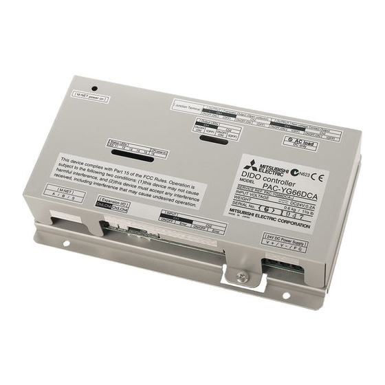
DIDO controller
PAC-YG66DCA
Installation/Instruction Manual
Before using the DIDO controller, please read this installation/instruction manual carefully to ensure proper operation.
Keep this installation/instruction manual for future reference.
Contents
1.
Safety Precautions .............................................. 1
2.
Device Capabilities ............................................. 1
3.
Confirmation of Parts .......................................... 2
4.
Specifications ...................................................... 2
4-1.
Product Specifications ....................... 2
4-2.
External View ..................................... 3
5.
Example of System Configuration....................... 3
6.
Installation Method .............................................. 4
6-1.
Parts to be Procured Locally .............. 4
6-2.
Installation Procedure ........................ 4
7.
Wiring Method ..................................................... 6
7-1.
Names of Parts .................................. 6
7-2.
M-NET Transmission Line ................. 7
7-3.
Connecting the Signal Lines .............. 7
(Channels 1 and 2) ............................ 8
(1) Inputs ................................................. 8
(a) Non-voltage a Contact Inputs....... 8
(2) Outputs .............................................. 8
Outputs......................................... 8
(Open Collector) ........................... 9
(Channels 3 to 6) ............................. 10
(1) Expansion Inputs/Outputs................ 10
8.
Initial Setting Procedure .................................... 11
9.
Switch List ......................................................... 12
10.
Display Content................................................. 13
10-1.
Display Content List ......................... 13
10-2.
Display ............................................. 14
11.
Test Run ........................................................... 14
Page
Advertisement
Table of Contents

Subscribe to Our Youtube Channel
Related Manuals for Mitsubishi Electric PAC-YG66 DCA-J


Summary of Contents for Mitsubishi Electric PAC-YG66 DCA-J
-
Page 1: Table Of Contents
Mitsubishi Electric Air Conditioner Network System DIDO controller PAC-YG66DCA Installation/Instruction Manual Contents Page Safety Precautions ..........1 Device Capabilities ..........1 Confirmation of Parts .......... 2 Specifications ............2 4-1. Product Specifications ....... 2 4-2. External View ........3 Example of System Configuration....... 3 Installation Method .......... -
Page 2: Safety Precautions
Safety Precautions • Before using the device, thoroughly read the following safety precautions and use as directed. • Hazards and levels of danger that can occur due to incorrect handling are classified by the following symbols. Warning Incorrect handling can result in death, serious injury, etc. Caution Incorrect handling can result in injury or damage to the building or its contents. -
Page 3: Confirmation Of Parts
Confirmation of Parts • Confirm that the box contains the following parts. Number Part Name Quantity DIDO controller Installation/instruction manual (this document) * In addition to the parts mentioned above, other parts need to be procured locally in order to operate this device. Furthermore, other Mitsubishi optional parts may be required depending on how the device is to be used. -
Page 4: External View
4-2. External View 111 ( 4 200 ( 7 45 ( 1 150 ( 5 52 ( 2 46.5 ( 1 DIDO controller PAC-YG66DCA [ OUTPUT ] Transistor Output 24 VDC [ OUTPUT ] Non-voltage Contact Output [ Junction Terminal ] ON/OFF,(ON) (OFF) ON/OFF,(ON) -
Page 5: Installation Method
Installation Method 6-1. Parts to be Procured Locally Prepare the following parts to install this device. Required Part Specification Unit fixing screws M4 screw × 4 Power source: 24 VDC±10% 0.2 A (Minimum loading), SELV circuit, power line with grounding terminal Ripple noise: Lower than 200 mVp-p Compatible specification Authorized or CE marked products... - Page 6 (1) Fix the top of this unit to the control panel at two points by loosely tightening the screws (M4) that were procured locally. Fix the bottom in place with two screws and then tighten all four of the screws. Screw pitch Unit: mm (in) (2) To remove the cover, as shown in the figure, remove the two screws for fixing the cover in place and then remove the cover by...
-
Page 7: Wiring Method
(3) Refer to "7 Wiring Method" and connect the wires for the power line, M-NET transmission line, and input/output signal lines. Input Power line/Output M-NET Caution: • Perform wiring so that the terminal block is not strained. If strained, use a wire guide or junction terminal to alleviate the Relay stress on the terminal block. -
Page 8: Connecting The Power Line And M-Net Transmission Line
7-2. Connecting the Power Line and M-NET Transmission Line Tightening torque for terminal screws: 1 N·m Connect the device to a power supply unit (PAC-SC50KUA) for the transmission line or an outdoor unit (either a centralized CN17 control line or indoor control line can be connected). CN16 * Only the M-NET circuitry of this device receives the power from the A/B/S... -
Page 9: Standard Terminals (Channels 1 And 2)
7-3-1. Standard Terminals (Channels 1 and 2) (1) Inputs (a) Non-voltage a Contact Inputs * To use these, various settings need to be configured. Refer to "8 Initial Setting Procedure". Note: • Connect the operate/stop (ON/OFF) inputs so that closing the contact operates (ON) the device and opening the contact stops (OFF) the device. -
Page 10: (B) Transistor Outputs (Open Collector)
(b) Transistor Outputs (Open Collector) * To use these, various settings need to be configured. Refer to "8 Initial Setting Procedure". Caution: • When X1, X2, Y1 and Y2 relays are 24 VDC used, select ones that satisfy the Power following specifications. -
Page 11: Expansion Connectors (Channels 3 To 6)
7-3-2. Expansion Connectors (Channels 3 to 6) (1) Expansion Inputs/Outputs * Purchase an optional external input/output adapter (model: PAC-YG10HA) when using expansion inputs/ outputs. * To use these, various settings need to be configured. Refer to "8 Initial Setting Procedure". Line Onsite PAC -YG10HA Function... -
Page 12: Initial Setting Procedure
Initial Setting Procedure After completing the procedures described in "6 Installation Method" and "7 Wiring Method," set the initial settings in accordance with the procedure described below. (1) M-NET address settings Note: • An address from 01 to 50 can be set. •... -
Page 13: Switch List
Switch List Switch Channel Function Setting Remark SW01 Select the output operation for when an emergency Emergency stop command Disabled Enabled stop command is received from a system enable setting controller. Error input logic setting a contact b contact – Channel 1 Error interlock stop output Select whether to interlock and stop output for error... -
Page 14: Display Content
Display Content The LEDs of this device indicate the operation output status, operation input status, and error status of this device. 10-1. Display Content List Display Item Display LED Content Condition Switch Note :On, :Off, :Flashing 03-6 03-7 Power supply status (1) Power supply to LED16 : Lights when the CPU is energized. -
Page 15: Communication Error Status Display
10-2. Communication Error Status Display If a communication error occurs, a 4-digit error code will be repeatedly displayed according to the steps shown below. Communication error status display consists of the following 10 steps. This operation is performed repeatedly to indicate the 4-digit error code for the communication error. - Page 16 This product is designed and intended for use in the residential, commercial and light-industrial environment. This product at hand is • Low Voltage Directive 73/23/EEC based on the following • Electromagnetic Compatibility Directive EU regulations: 2004/108/EC NOTE: This equipment has been tested and found to comply with the limits for a Class B digital device, pursuant to Part 15 of the FCC Rules.
Need help?
Do you have a question about the PAC-YG66 DCA-J and is the answer not in the manual?
Questions and answers