Table of Contents
Advertisement
Quick Links
WT03594X04
GB
CITY MULTI Control System
and Mr. SLIM Air Conditioners
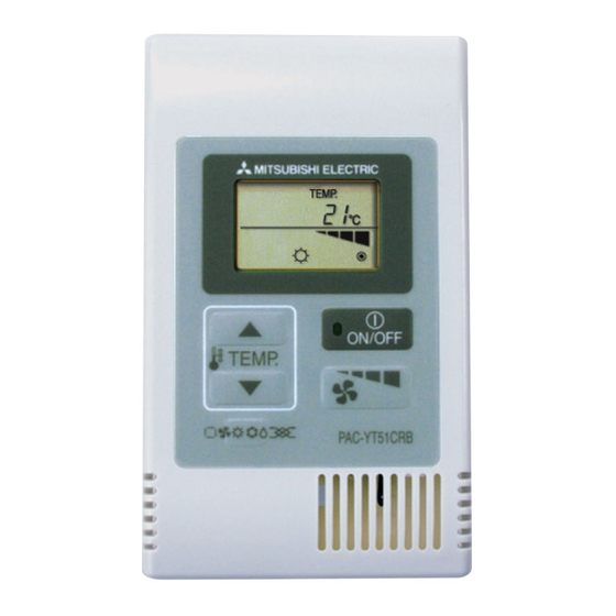
Simple MA Controller
Installation Manual
This instruction manual describes how to install the Simple MA Controller for Mitsubishi Building Air Conditioning Systems, direct expansion type CITY
MULTI air conditioner indoor units ("-A" type and later), and Mr. SLIM air conditioners. Please read this manual thoroughly and install the remote
controller accordingly. For information on how to wire and install the air conditioning units, refer to the installation manual for them.
1 Safety Precautions
● Read these Safety Precautions and perform installation work accordingly.
● The following two symbols are used to dangers that may be caused by incorrect use and their degree:
WARNING
This symbol denotes what could lead to serious injury or death if you misuse the PAC-YT51CRB
CAUTION
This symbol denotes what could lead to a personal injury or damage to your property if you misuse the PAC-YT51CRB
● After reading this installation manual, give it and the indoor unit installation manual to the end user.
● The end user should keep this manual and the indoor unit installation manual in a place where he or she can see it at anytime. When someone moves
or repairs the PAC-YT51CRB, make sure that this manual is forwarded to the end user.
Ask your dealer or technical representative to install the unit.
Any deficiency caused by your own installation may result in an electric shock
or fire.
Install in a place that is strong enough to withstand the weight of the
PAC-YT51CRB.
Any lack of strength may cause the PAC-YT51CRB to fall down, resulting in
personal injury.
Firmly connect the wiring using the specified cables. Carefully check
that the cables do not exert any force on the terminals.
Improper wiring connections may produce heat and possibly a fire.
Never modify or repair the PAC-YT51CRB by yourself.
Any deficiency caused by your modification or repair may result in an electric
shock or fire.
Consult with your dealer about repairs.
Do not install in any place exposed to flammable gas leakage.
Flammable gases accumulated around the body of PAC-YT51CRB may cause
an explosion.
Do not use in any special environment.
Using in any place exposed to oil (including machine oil), steam and sulfuric
gas may deteriorate the performance significantly or give damage to the com-
ponent parts.
Wire so that it does not receive any tension.
Tension may cause wire breakage, heating or fire.
Completely seal the wire lead-in port with putty etc.
Any dew, moisture, insects entering the unit may cause an electric shock or a
malfunction.
When installing the remote controller in a hospital or communication
facility, take ample countermeasures against noise.
Inverters, emergency power supply generators, high-frequency medical equip-
ment, and wireless communication equipment can cause the remote control-
ler to malfunction or to fail. Radiation from the remote controller may effect
communication equipment and prevent medial operations on the human body
or interfere with image transmission and cause noise.
Never contact the power supply with the control wiring terminals.
Doing so will certainly cause the controller to catch fire.
2 Checking the Supplied Parts
Check that the box includes the following parts in addition to this installation manual:
Remote Controller Model Name
PAC-YT51CRB
NOTE: The parts listed below must be purchased separately.
(1) Cable connecting the remote controller to the indoor unit:
Use the cable specified below.
Cable type VCTF or CVV (2-core): 0.75 – 1.25 mm
* CVV is a control cable which is sheathed in polyvinyl chloride with polyvinyl insulated wires inside.
WARNING
CAUTION
Enclosed Parts
(1) Simple MA Controller .......................................................... 1
(2) Cross-recessed pan-head screws ...................................... 2
(3) Operation manual ............................................................... 3
2
(stranded 16 to 20 AWG) or equivalent
PAC-YT51CRB
Ensure that installation work is done correctly following this installa-
tion manual.
Any deficiency caused by installation may result in an electric shock or fire.
All electrical work must be performed by a licensed technician, accord-
ing to local regulations and the instructions given in this manual.
Any lack of electric circuit or any deficiency caused by installation may result
in an electric shock or fire.
Do not move and re-install the PAC-YT51CRB yourself.
Any deficiency caused by installation may result in an electric shock or fire.
Ask your distributor or special vendor for moving and installation.
Do not install in any place at a temperature of more than 40
°
°
less than 0
C (32
F) or exposed to direct sunlight.
The PAC-YT51CRB may be deformed or may malfunction.
Do not touch any control button with your wet hands.
Doing so may cause an electric shock or a malfunction.
Do not wash with water.
Doing so may cause an electric shock or a malfunction.
Do not press any control button using a sharp object.
Doing so may cause an electric shock or a malfunction.
Do not touch any PCB (Printed Circuit Board) with your hands or with
tools. Do not allow dust to collect on the PCB.
Doing so may cause fire or an electric shock.
Do not install in any place where acidic or alkaline solution or special
spray are often used.
Doing so may cause an electric shock or malfunction.
Do not install in any steamy place such a bathroom or kitchen.
Avoid any place where moisture is condensed into dew. Doing so may cause
an electric shock or a malfunction.
Use standard wires in compliance with the current capacity.
A failure to this may result in an electric leakage, heating or fire.
16(5/8) 16(5/8)
54(2-1/8)
°
°
C (104
F) or
h
6(1/4)
20
(13/16)
1.5 (1/16) or less
10
(3/8)
44(1-3/4)
1
Unit: mm (in)
Switch box
Advertisement
Table of Contents

Related Manuals for Mitsubishi Electric PAC-YT51CRB


Summary of Contents for Mitsubishi Electric PAC-YT51CRB
- Page 1 This symbol denotes what could lead to serious injury or death if you misuse the PAC-YT51CRB CAUTION This symbol denotes what could lead to a personal injury or damage to your property if you misuse the PAC-YT51CRB ● After reading this installation manual, give it and the indoor unit installation manual to the end user.
- Page 2 NOTE: If you need to use a cable extension longer than 10 m (32 ft), select an electric wire that meets the following specifications: Wire specification VCTF or CVV (2-core): 1.25 mm (stranded 16 AWG) or equivalent (2) The switch box is necessary for mounting. Use the switch box specified in the right. 3 How To Wire Transmission Line The wiring is different when the remote controller is connected to a CITY MULTI control system (“-A”...
- Page 3 (2) When grouping with difference refrigerant systems • Group using the remote controller wiring. Connect the remote controller to an arbitrary indoor unit of each refrigerant system you want to group. • When mixing different types of indoor units in the same group, always make the outdoor unit connecting the indoor unit with the most functions (wind velocity, vane, louver, etc.) the master unit (refrigerant address = 00).
- Page 4 - Forcing off the cover using a screwdriver that is less than 4 mm (5/32 in) wide may result in damage to the equipment. CAUTION - Attach the remote controller to a level surface. Do not overtighten the screws, otherwise the case may become deformed or break.
- Page 5 - Confirmation end display (When - Registered indoor unit ad- 7 Press the [ON/OFF] button, and register the set indoor unit address LOSSNAY or OA processing unit dress does not exist. and LOSSNAY address. is not connected.) - Registration end display The indoor unit address and “IC”...
- Page 6 7 Setting No. selection → 3 (remote controller fixed) TEMP. (Buttons B, C and D operation) 8 Register (Press button A.) PAC-YT51CRB End? ? Ending function display (Press buttons D and C simultaneously.) [Procedure] (Set only when change is necessary.) 1 Check the set contents of each mode.
- Page 7 7 Select the setting contents of the selected mode. Select the setting No. using the B [TEMP. ( )] and C [TEMP. ( When the D [ (Fan Speed Adjustment)] button is pressed, the buttons. current setting No. flashes. Use this to check the currently set con- tents.
- Page 8 2 Switch to the remote controller check mode. When the B [TEMP. ( )] button and D [ When the A [ON/OFF] button is pressed, (Fan Speed Adjust- ment)] button are pressed simultaneously for 5 seconds or longer, remote controller check begins. the figure shown below is displayed.
Need help?
Do you have a question about the PAC-YT51CRB and is the answer not in the manual?
Questions and answers