Table of Contents
Advertisement
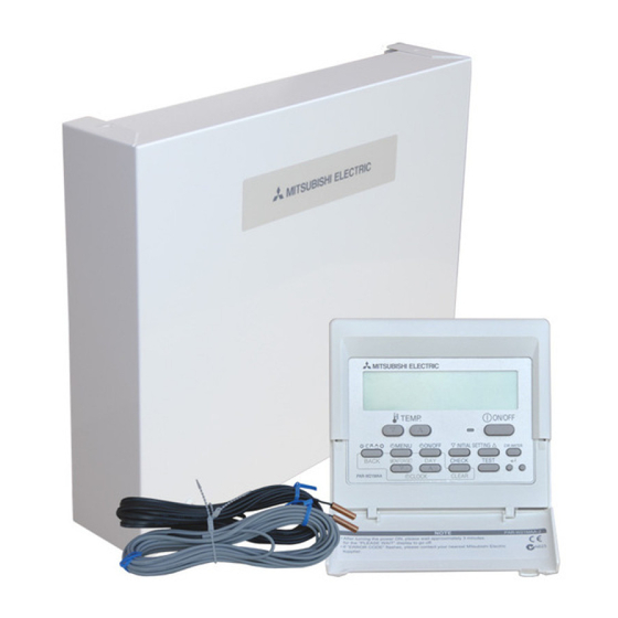
FLOW TEMP. CONTROLLER [MASTER] (Cased)
PAC-IF061B-E
PAC-IF062B-E
PAC-IF063B-E
FLOW TEMP. CONTROLLER [SLAVE] (Cased)
INSTALLATION MANUAL
For safe and correct use, read this manual thoroughly before installing the FTC unit.
OPERATION MANUAL
For safe and correct use, please read this operation manual thoroughly before operating the FTC unit.
FOR INSTALLER
FOR USER
English
Advertisement
Table of Contents

Related Manuals for Mitsubishi Electric PAC-IF061B-E


Summary of Contents for Mitsubishi Electric PAC-IF061B-E
- Page 1 FLOW TEMP. CONTROLLER [MASTER] (Cased) PAC-IF061B-E PAC-IF062B-E PAC-IF063B-E FLOW TEMP. CONTROLLER [SLAVE] (Cased) PAC-SIF051B-E INSTALLATION MANUAL FOR INSTALLER English For safe and correct use, read this manual thoroughly before installing the FTC unit. OPERATION MANUAL FOR USER For safe and correct use, please read this operation manual thoroughly before operating the FTC unit.
-
Page 2: Table Of Contents
“FTC (Slave)” is the abbreviation of “Flow Temperature Controller [Slave]”, which is described as “FTC (Slave)” in this manual. In this manual, “FTC” that is not followed by “(Master)” or “(Slave)” means “FTC (Master and Slave)”. Mitsubishi Electric is not responsible for the failure of locally supplied parts. 1. Safety precautions FOR INSTALLER Before installing the FTC unit, make sure you read all the “Safety pre-... -
Page 3: Safety Precautions
1. Safety precautions 1.4 Before starting the test run Caution: • B efore starting operation, check that all protective parts are correctly in- • T urn on the main power switch of the outdoor unit more than 12 hours stalled. Make sure not to get injured by touching high voltage parts. before starting operation. Starting operation immediately after turning on • D o not touch any switch with wet hands. There may be a risk to get an the power switch can severely damage the internal parts. -
Page 4: Installing The Ftc Unit
Hole for installation Screw Wall Base Note: Do not remove the screws as the screws are the component parts of the cover and are not used for the installation of cover. PAC-IF061B-E 4.0 kg Weight PAC-IF062/063B-E 4.4 kg PAC-SIF051B-E 1.9 kg Allowable ambient temperature 0 to 35°C... - Page 5 3. System The FTC (Master) is designed for use with a number of heat pump systems. Please refer to the following table to find the relevant installation information for your system. For multiple outdoor units control with FTC (Slave), see section 9. 3.1 First step (Electrical work) Reference Power supplies...
-
Page 6: System
3. System 3.3 Third step (Functions setting) Immersion Booster Reference DHW tank System diagram Thermistor Remarks heater heater function section Present Absent Present For heating THW1: Flow water temp. and DHW THW2: Return water temp. DHW tank THW5 THW5: Tank water temp. 3-way valve ( THW1 Heat emitter... - Page 7 3. System 3.4 Fourth step (Functions setting) * Make sure to check the followings for your safety when designing a system. These are the minimum requirement for the safe use of FTC unit. Parts name Requirement Flow switch It is required to protect system from the effects of insufficient flow. Flow sensor It is required to detect an error in flow rate.
- Page 8 3. System From the previous page. Parts name Requirement Water circulation pump (1) Packaged-type units Heating PUHZ-W85 PUHZ-W50 19.0 19.0 Available range Available range 17.0 17.0 15.0 15.0 13.0 13.0 11.0 11.0 11.0 10.0 12.0 13.0 14.0 10.0 12.0 14.0 16.0 18.0 20.0...
- Page 9 3. System Parts name Requirement Booster heater General * Consider necessity and capacity of booster heater to meet the following points. (1) Heating capacity and flow water temperature should always be sufficient. (2) System can increase the temperature of the stored water in tank to inhibit legionella bacterium growth. (Note) System without neither booster heater or immersion heater, ‘Legionella Prevention Mode’...
- Page 10 3. System 3.5 Local system 1-zone temperature control Zone1 Zone1 1-zone temperature control (2-zone valve ON/OFF control) 2-zone temperature control Zone1 Zone1 Zone2 Zone2 1-zone temperature control with boiler 2-zone temperature control with boiler Zone1 Zone1 Zone2 1. Zone1 heat emitters (e.g. radiator, fan coil unit) (local supply) 10.
- Page 11 3. System 3.7 Energy monitor End user can monitor accumulated*1 ‘Consumed electric energy’ and ‘Delivered heat energy’ in each operation mode*2 on the main remote controller. *1 Monthly and Year to date *2 - DHW operation - Space heating - Space cooling *3 Not available during Multiple outdoor unit control.
- Page 12 (DHW tank) (DHW tank) switch switch : PAC-IF061B-E : PAC-IF062/063B-E <Fig. 4.1.2> Electrical connections 1 phase/3 phase *1 If the installed earth leakage circuit breaker does not have an over-current protection function, install a breaker with that function along the same power line.
-
Page 13: Electrical Work
(DHW tank) switch : PAC-IF061B-E <Fig. 4.1.5> : PAC-IF062/063B-E Electrical connections 1 phase/3 phase *1 If the installed earth leakage circuit breaker does not have an over-current protection function, install a breaker with that function along the same power line. - Page 14 4. Electrical work 4.2 Connecting the main remote controller 4.2.1 Connect the main remote controller cable to FTC (Master) Connect the main remote controller cable to 1 and 2 on the terminal block (TBI. 2) on the FTC (Master) controller. <Fig. 4.2.1> Wiring wire No.
- Page 15 4. Electrical work 5. Install the bottom case. ■ Installation using a switch box ■ Direct wall installation • When installing the bottom case in the switch box, secure at least two • Thread the cable through the slot provided. corners of the switch box with screws.
- Page 16 4. Electrical work 9. Fit the top case and the front cover onto the bottom case. The top case assembly (fitted with the front cover at factory shipment) has two tabs on top. Hook the tabs onto the bottom case and snap the top case onto the bottom case into place.
- Page 17 (option) (option) This option features the main remote controller and the Mitsubishi Electric wireless remote controller. The wireless remote controller is used to monitor room temperature and can be used to make changes to the space heating settings, boost DHW (*1) and 20.0°C...
- Page 18 The thermostat is wired to IN6 on FTC (Master). (If the thermostat is allocated to Zone1, it is wired to IN1 on TBI.1.) (Refer to 4.5.) Control option B This option features the main remote controller, the Mitsubishi Electric thermistor and a locally supplied thermostat that are wired to FTC (Master). Room temperature...
- Page 19 4. Electrical work 4.4. Connecting the thermistor cables CNW5 CNW12 Connect the thermistor for the FTC (Master) controller. For multiple outdoor units control with FTC (Slave), see section 9. CN21 4.4.1 Connecting the room temp. thermistor (TH1) cable TH1 is an optional part (PAC-SE41TS-E). CN20 TH1 is required to use the auto adaptation function. However, when room tempera- ture detection is conducted by the main remote controller or the wireless remote controller (optional), this part is not required.
- Page 20 4. Electrical work 4.4.5. Thermistor position and necessity <Thermistor position and necessity> Outdoor unit type DHW tank THW1 THW2 THW5 Present Split Absent — Present — Packaged Absent — — : Necessary. Connect the thermistor. —: Not necessary. The thermistor is not required, do not connect. PACKAGED type outdoor unit with DHW tank and booster heater SPLIT type outdoor unit with DHW tank and booster heater DHW tank...
- Page 21 4. Electrical work 4.5 Connecting inputs/outputs For multiple outdoor units control with FTC (Slave), see section 9. CN01 TBO.1 (WHT) CNP1 (WHT) When the wires are wired to adjacent terminals 6.3A 250V 10A 250V use ring terminals and insulate the wires. CNP4 TBO.2 (RED) CN3C...
- Page 22 4. Electrical work Thermistor inputs Name Terminal block Connector Item Optional part model — CN20 Thermistor (Room temp.) (Option) *1 PAC-SE41TS-E — CN21 Thermistor (Ref. liquid temp.) *2 — THW1 — CNW12 1-2 Thermistor (Flow water temp.) — THW2 — CNW12 3-4 Thermistor (Return water temp.) —...
- Page 23 4. Electrical work 4.6 Wiring for heater <Care to be taken when connecting a booster heater(s)> The initial setting assumes that the connected booster heater(s) has a built-in direct cut-off thermostat. <Fig. 4.6.1> When the connected booster heater(s) has a built-in indirect cut-off thermostat, perform wiring according to the following items. < Fig. 4.6.2> •...
- Page 24 4. Electrical work 4.7 Wiring for 2-zone temperature control 1. Water circulation pump 2 (Zone1 water circulation pump) / Water circulation pump 3 (Zone2 water circulation pump) Electrically wire water circulation pumps 2 and 3 to the appropriate output terminals. (Refer to “Outputs” in 4.5.) 2.
- Page 25 4. Electrical work 4.10 Installation procedure for DHW tank Note: Specification of 2-way valve (local supply) • B e aware that the respective DHW operations are greatly effected by the • Power supply: 230V AC selections of the components such as tank, immersion heater, or the • Current: 0.1A Max. (If over 0.1A you must use a relay) like. •...
- Page 26 (9) FTC supports FAT file system but not NTFS file system. (10) Mitsubishi Electric is not liable for any damages, in whole or in part, including failure of writing to an SD memory card, and corruption and loss of the saved data, or the like.
- Page 27 Indoor unit model SW1 SW1-1 Boiler WITHOUT Boiler WITH Boiler SW1-2 Heat pump maximum outlet water temperature 55ºC 60ºC ON *1 OFF: PAC-IF061B-E SW1-3 DHW tank WITHOUT DHW tank WITH DHW tank ON : PAC-IF062/063B-E OFF: PAC-IF061B-E SW1-4 Immersion heater...
-
Page 28: Dip Switch Setting
5. Dip Switch setting 5.2 Outdoor unit type Set Dip SW 1-7 to set the outdoor unit type. Dip SW 1-7 Setting Note Split type Necessary to connect TH2 Packaged type Not necessary to connect TH2 Set Dip SW 1-2 to set the heat pump maximum outlet water temperature. Dip SW 1-2 Setting 55°C... - Page 29 5. Dip Switch setting <Summary of Function setting> Dip SW 1-3 Dip SW 1-4 Dip SW 1-5 Dip SW 1-6 System diagram (DHW tank) (Immersion heater) (Booster heater) (BH function) (WITH DHW tank) (WITHOUT (WITH (For heating and DHW) DHW tank THW5 immersion heater) booster heater) 3-way valve ( THW1 Heat emitter Booster heater THW2 (WITH DHW tank)
- Page 30 5. Dip Switch setting 5.4 Operation setting Set Dip SW 1-8 to set whether the system has a wireless remote controller. Dip SW 1-8 Setting WITHOUT wireless remote controller WITH wireless remote controller Set Dip SW 2-1 to set the room thermostat 1 input (IN1) logic. Dip SW 2-1 Setting Operation stop at thermostat short...
- Page 31 5. Dip Switch setting 5.5 Emergency mode (Heater only operation) The emergency mode is available when a failure on the outdoor unit of the heat pump or a communication error occurs. This mode uses booster heater or immersion heater as a heat source and automatically controls between the DHW mode and the heating mode. When the system is not incorporated with heater, the emergency mode is not available.
-
Page 32: Before Test Run
6. Before test run 6.1. Check After completing installation and the wiring and piping of the local application and outdoor units, check for refrigerant leakage, looseness in the power supply or control wir- ing, wrong polarity, and power cable is securely connected. Use a 500-volt megohmmeter to check that the resistance between the power supply terminals and ground is at least 1.0MΩ. -
Page 33: Cautions
(Marking for WEEE) Your MITSUBISHI ELECTRIC product is designed and manufactured with high quality materials and components which can be recycled and reused. This symbol means that electrical and electronic equipment, at their end-of-life, should be disposed of separately from your household waste. -
Page 34: Main Remote Controller Operation
7. Main remote controller operation 7.2 Main remote controller <Main remote controller parts> Letter Name Function Screen Screen in which all information is displayed Menu Access to system settings for initial set up and modifications. Back Return to previous menu. Confirm Used to select or save. - Page 35 7. Main remote controller operation Setting the Main remote controller After the power has been connected to the outdoor and FTC unit (See chapter 4.1) the initial system settings can be entered via the main remote controller. 1. Check all breakers and other safety devices are correctly installed and turn on power to the system. 2.
- Page 36 7. Main remote controller operation <Main remote controller Menu Tree> Unrestricted access Initial Installer only Shaded items relate Main screen * Short press for 1 Zone system. to DHW functions. These are only avail- Information able if the system in- Option Forced DHW ON ( )/OFF cludes a DHW tank.
- Page 37 7. Main remote controller operation <Main remote controller Menu Tree> Unrestricted access <Continued from the previous page.> Installer only Shaded items relate Initial to DHW functions. Main Main screen These are only avail- menu able if the system in- Manual operation Menu cludes a DHW tank.
- Page 38 7. Main remote controller operation General Operation In general operation the screen displayed on the main remote controller will be shown as in the figure on the right. This screen shows the target temperature, space heating mode, DHW mode (if DHW tank is present in system), any additional heat sources being used, holiday mode, and the date and time.
- Page 39 7. Main remote controller operation <Room sensor settings> For room sensor settings it is important to choose the correct room sensor de- pending on the heating mode the system will operate in. 1. From the Initial settings menu select Room sensor settings. 2.
- Page 40 7. Main remote controller operation Domestic Hot Water (DHW)/Legionella Prevention The domestic hot water and legionella prevention menus control the operation of DHW tank heat ups. <DHW mode settings> 1. Highlight the hot water icon and press CONFIRM. 2. Use button F1 to switch between Normal and ECO heating modes. 3.
- Page 41 7. Main remote controller operation Explanation of Legionella Prevention Mode operation DHW tank temp. Stop Stop • At the time entered by the installer ‘Start time’ flow of useful heat from the sys- Restart tem is diverted to heat the water in the DHW tank. Stop temp. •...
- Page 42 7. Main remote controller operation Holiday Mode Holiday mode can be used to keep the system running at lower flow temperatures and thus reduced power usage whilst the property is unoccupied. Holiday mode can run either flow temp., room temp., heating, compensation curve heating and DHW all at reduced flow temperatures to save energy if the occupier is absent.
- Page 43 7. Main remote controller operation 5. In the preview menu screen press F4 button. Preview screen 6. First select the days of the week you wish to schedule. 7. Press F2/F3 buttons to move between days and F1 to check or uncheck the box.
- Page 44 7. Main remote controller operation Service Menu The service menu provides functions for use by installer or service engineer. It is NOT intended the home owner alters settings within this menu. It is for this reason password protection is required to prevent unauthorised access to the service settings. The factory default password is "0000".
- Page 45 7. Main remote controller operation <Operation settings> Heating operation This function allows operational setting of flow temperature range from the Ecodan and also the time interval at which the FTC collects and processes data for the auto adaptation mode. Menu subtitle Function Range Unit...
- Page 46 7. Main remote controller operation <Energy monitor settings> In this menu, all parameters required to record the consumed electric energy and the delivered heat energy which is displayed on the main remote controller can be set. The parameters are an electric heater capacity, supply power of water pump and heat meter pulse.
- Page 47 7. Main remote controller operation Engineers Forms Should settings be changed from default, please enter and record new setting in ‘Field Setting’ column. This will ease resetting in the future should the system use change or the circuit board need to be replaced. Commissioning/Field settings record sheet Main remote controller screen Parameters...
- Page 48 7. Main remote controller operation Engineers Forms Commissioning/Field settings record sheet (continued from the previous page) Default Field Main remote controller screen Parameters Notes setting setting Service menu Pump speed Pump speed (1 - 5) Heat source setting Standard/Heater/Boiler/Hybrid *7 Standard Operation Heating operation Flow temp.range Min.temp. (25 - 45°C) 30°C settings Max.temp.
- Page 49 8. Troubleshooting <Troubleshooting by inferior phenomena> Fault symptom Possible cause Explanation - Solution Main remote controller 1. There is no power supply to main remote 1. Check LED2 on FTC (Master). (See <Figure 4.5.1>.) display is blank. controller. (i) When LED2 is lit. Check for damage or contact failure of the main remote controller wiring.
-
Page 50: Troubleshooting
Contact your Mitsubishi Electric dealer. 7. Immersion heater cut-out tripped. 7. Check immersion heater thermostat and press reset button, located on immersion heater boss, if safe. - Page 51 Contact your Mitsubishi Electric dealer. 5. Immersion heater cut-out has been triggered. 5. Check immersion heater thermostat and press reset button located on immersion heater boss, if safe.
- Page 52 8. Troubleshooting Fault symptom Possible cause Explanation - Solution In 2-zone tempera- When Zone1 and Zone2 are both in heating Normal action no action necessary. ture control, only mode, the hot water temperature in Zone2 Zone2 does not does not exceed that in Zone1. reach the set tem- Faulty wiring of motorized mixing valve Refer to "4.7 Wiring for 2-zone temperature control".
- Page 53 8. Troubleshooting Fault symptom Possible cause Explanation - Solution 27 The cooling system When the water in the circulation circuit is un- Normal operation. duly hot, Cooling mode starts with a delay for does not cool down to the protection of the outdoor unit. the set temperature.
- Page 54 9. Multiple outdoor units control 9.1 Wiring for multiple outdoor units control To establish a larger system, up to 6 outdoor units of the same model can be con- nected in one system. (Slave) (Master) Note: PUHZ-FRP outdoor unit is not available for multiple outdoor units control. Main remote controller Master Max. 6 units 9.1.1 Requirements <Outdoor unit>...
-
Page 55: Multiple Outdoor Units Control
9. Multiple outdoor units control System 2: Heating/Cooling & DHW system Wiring Component • Install DHW tank toward the outdoor unit , relative to the low loss header. Master Slave 1 *4 Slave 2 • Wire 3-way valve or 2-way valve 1, 2 to FTC (slave unit). Booster heater (local supply) •... - Page 56 9. Multiple outdoor units control System 3: 2-zone temperature control • Install a mixing tank (local supply) for 2-zone temperature control. • Install a low loss header (local supply). • Install booster heater toward the local system, relative to the low loss header. •...
- Page 57 9. Multiple outdoor units control System 4: Heating/Cooling system (with Boiler) • Install a mixing tank (local supply) for connection of the boiler. • Install a low loss header (local supply). • Install booster heater between low loss header and mixing tank. • For more details, refer to the installation manual of PAC-TH011HT-E. Boiler Heating/Cooling Outdoor unit...
- Page 58 1. Power cable is run from the outdoor unit to a slave unit. 2. FTC (Slave) has independent power source. FTC (Master) (PAC-IF061B-E) used as slave • For wiring as a slave controller, refer to "4.1 Electrical connection". *1 *1 Do not connect the power cable to the booster heater because it does not work in slave controller setting.
- Page 59 9. Multiple outdoor units control Option 2: FTC (Slave) powered by independent source If FTC (Slave) and outdoor units have separate power supplies, the following re- CN108 quirements MUST be carried out: LED1 • Remove the short-circuited connector (CNS2) on FTC (Slave). (see <Fig. 9.3.5>) •...
- Page 60 9. Multiple outdoor units control 9.4 Main remote controller wiring (a) Wire the main remote controller to TBI.2 RC terminals on the master unit. The main remote controller must NOT be connected to a slave unit. (b) Use the daisy chain wiring method to wire the master unit and slave units by connecting TBI.2 RC terminals. *1 *1 The maximum length between each units wiring is 10 m.
- Page 61 9. Multiple outdoor units control 9.6 Dip switch functions <Outdoor unit> • Set refrigerant address on each outdoor unit from 1 to 6. Note: Do NOT use refrigerant address 0 as 0 is used for FTC (Master). The address range is from 1 to 6. Split model (SW1-3 to SW1-6) Packaged model (SW7-3 to SW7-6) Refrigerant address number Refrigerant address number Dip switch Dip switch Add. 1 Add.
- Page 62 9. Multiple outdoor units control 9.7 Connecting inputs/outputs When the wires are wired to adjacent terminals use ring terminals and insulate the wires. <Electrical connection for master controller> • Refer to "4.5 Connecting inputs/outputs" <Electrical connection for slave controller> PAC-IF06*B-E CN01 TBO.1 (WHT) When the wires are wired to adjacent terminals use ring terminals and insulate the wires.
- Page 63 9. Multiple outdoor units control PAC-SIF051B-E CN108 LED1 FTC (Slave) LED4 LED3 CNS2 (RED) CNW12 CN21 (RED) (YLW) TBIN TBOUT <Fig. 9.7.4> Signal inputs Name Terminal block Connector Item OFF (Open) OFF (Short) TBIN 1-2 — Communication cable between indoor units —...
- Page 64 9. Multiple outdoor units control Hydrobox CN01 TBO.1 (WHT) CNP1 (WHT) When the wires are wired to adjacent terminals use ring terminals and insu- late the wires. 6.3A 250V 10A 250V CNP4 TBO.2 (RED) CN3C (BLU) LED1 CNPWM CNV1 TBO.3 (WHT) (WHT) CNRF...
- Page 65 9. Multiple outdoor units control Basic Troubleshooting for multiple outdoor units control Fault symptom Possible cause Explanation - Solution Main remote controller 1. There is no power supply to main remote 1. Check LED2 on the master controller. (See <Figure 4.5.1>.) display is blank. controller.
-
Page 66: Supplementary Information
2. Go to Service menu > Operation settings > Boiler settings to make detailed settings for “Hybrid” above . *4 The “Hybrid” automatically switches heat sources between Heat pump (and Electric heater) and boiler. Product fiche of temperature control (a) Supplier’s name: MITSUBISHI ELECTRIC CORPORATION (b) Supplier’s model identifier: PAR-WT50R-E and PAR-WT51R-E (c) The class of the temperature control:... -
Page 67: Local Application Factors
Local application factors * This FTC is designed to connect Mr.Slim/Ecodan inverter outdoor unit of MITSUBISHI ELECTRIC to local systems. Please check the following when designing the local system. * MITSUBISHI ELECTRIC does not take any responsibility for the local system design. - Page 68 с настоящото декларира на своя отговорност, че описаните по-долу компоненти за отоплителна система са годни за експлоатация в жилищна, търговска и лекопромишлена среда: MITSUBISHI ELECTRIC, PAC-IF061B-E, PAC-IF062B-E, PAC-IF063B-E, PAC-SIF051B-E Note: Its serial number is on the nameplate of the product. Obs: Serienumret finns på produktens namnplåt.
- Page 70 Please be sure to put the contact address/telephone number on this manual before handing it to the customer. HEAD OFFICE: TOKYO BUILDING, 2-7-3, MARUNOUCHI, CHIYODA-KU, TOKYO 100-8310, JAPAN BH79D449H04 Printed in the UNITED KINGDOM...
Need help?
Do you have a question about the PAC-IF061B-E and is the answer not in the manual?
Questions and answers