Table of Contents
Advertisement
Quick Links
GB
Mitsubishi Electric Air Conditioner Network System
PI controller
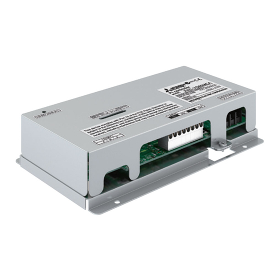
PAC-YG60MCA
Installation/Instruction Manual
Before using the device carefully read this installation/instruction manual to ensure proper operation.
Keep this manual for future reference and give it to the technician when the device is reinstalled or repaired.
Table of Contents
1.
Safety Precautions ..............................................1
2.
Usage ..................................................................2
3.
Parts List..............................................................2
4.
Specifications ......................................................2
4-1.
Device Specifications .........................2
4-2.
External Dimensions...........................3
5.
Example of System Configuration .......................4
6.
Installation ...........................................................5
6-1.
Parts Purchased Separately...............5
6-2.
Installation Instructions .......................6
7.
Wiring Instructions ...............................................7
7-1.
Terminal Diagram ...............................7
7-2.
Transmission Lines.............................8
7-3.
Connecting the Signal Lines...............9
8.
Initial Settings ....................................................10
9.
Dip Switch Functions .........................................11
10.
LED Display Designations .................................12
10-1.
Pulse Input and Error Displays .........12
10-2.
Communication Error Displays .........12
11.
System Operation Test......................................13
12.
Precautions for Expansion.................................13
Page
Advertisement
Table of Contents

Related Manuals for Mitsubishi Electric PAC-YG60MCA


Summary of Contents for Mitsubishi Electric PAC-YG60MCA
-
Page 1: Table Of Contents
Mitsubishi Electric Air Conditioner Network System PI controller PAC-YG60MCA Installation/Instruction Manual Table of Contents Page Safety Precautions ..........1 Usage ..............2 Parts List..............2 Specifications ............2 4-1. Device Specifications ......2 4-2. External Dimensions......3 Example of System Configuration .......4 Installation ............5 6-1. Parts Purchased Separately....5 6-2. -
Page 2: Safety Precautions
Safety Precautions • Thoroughly read the following safety precautions before use. • Hazards that can occur from incorrect handling are classified by the symbols below: Warning Incorrect handling can result in death, serious injury, etc. Caution Incorrect handling can result in bodily injury and/or structure damage. •... -
Page 3: Usage
Installation/instruction manual (this document) * In addition to the parts listed above, see your local Mitsubishi Electric dealer to purchase the other parts necessary to operate this device (Refer to section 6-1). Furthermore, depending on the application, other Mitsubishi Electric parts may be required. -
Page 4: External Dimensions
4-2. External Dimensions 46.5 This device complies with Part15 of the FCC Rules.Operation is subject to the following two conditions: (1)this device may not cause harmful interference, and (2)this device must accept any interference received, including interference that may cause undesired operation. [ 24 VDC Power Supply] 83.5 Unit: mm (in) -
Page 5: Example Of System Configuration
Example of System Configuration <Restrictions> Maximum of 5 units (total of 20 channels) per G(B)-50A However, the number of units that can be connected to a G(B)-50A is up to 50 including this device, an indoor unit, LOSSNAY unit, etc. * For the number of units that can be connected when controlling this device with TG-2000A, refer to the instruction manual for TG-2000A. -
Page 6: Installation
Installation 6-1. Parts Purchased Separately Prepare the following parts to install this device. Required Part Specification Unit fixing screws M4 screw × 4 (* M4: ISO metric screw thread) Power source: 24 VDC 0.2 A (Minimum loading), SELV circuit, power line with grounding terminal Ripple noise: Lower than 200 mVp-p Compatible specification Power supply for this... -
Page 7: Installation Instructions
6-2. Installation Instructions The PI controller PAC-YG60MCA does not have a waterproof structure. Be sure to install the PI controller inside a control panel that is located indoors. Prepare a control panel capable of storing this device such as the one shown in the figure. (Install the device in a control panel strong enough to withstand a weight of 0.6 kg [1... -
Page 8: Wiring Instructions
(3) Refer to "7. Wiring Instructions" and connect the wires for the power line, M-NET transmission line, and meter input signal lines. Meter input signal lines M-NET Power line Caution: Perform wiring so that the terminal block is not strained. If strained, use a wire guide or junction terminal to alleviate the PI controller... -
Page 9: Connecting The Power And M-Net Transmission Lines
7-2. Connecting the Power and M-NET Transmission Lines Tightening torque for terminal screws: 1 N·m Connect the M-NET transmission line of this device to a power supply unit (PAC-SC50KUA) for the transmission line or an outdoor unit (either a centralized control line or indoor control CN17 line can be connected). -
Page 10: Connecting The Signal Lines
7-3. Connecting the Signal Lines • Separately procure items such as terminal blocks and cables locally. • The maximum wire length is 100 m (328 ft). However, since the use of long wires makes the device susceptible to noise, using wires shorter than 10 m (32.8 ft) is recommended. (1) Pulse input (non-voltage a-contact) * To use these, various settings need to be configured. -
Page 11: Initial Settings
Initial Settings After completing the procedures described in "6. Installation" and "7. Wiring Instructions", set the initial settings in accordance with the procedure described below. (1) M-NET address settings Note: • An address from 01 to 50 can be set. •... -
Page 12: Dip Switch Functions
Dip Switch Functions Supported Function Remark Channel SW01 Channel 1 Use of input contact Set whether to use the Channel 1 input. Channel 2 Use of input contact Set whether to use the Channel 2 input. Channel 3 Use of input contact Set whether to use the Channel 3 input. -
Page 13: Led Display Designations
LED Display Designations The LEDs of this device indicate the pulse input status and error status of this device. 10-1.Pulse Input and Error Displays Display Item Display LED Content Note : On, : Off, : Flashing Power supply status (1) Power supply to LED16 : Lights when the CPU is energized. -
Page 14: System Operation Test
System Operation Test Use the following procedure to confirm operation of the system. (1) Configure the settings of this device and the system controllers (G(B)-50A Initial setting web browser or TG-2000A) while referring to "8. Initial Settings". (2) Perform an operation from a system controller and confirm whether a connected device can be operated normally. (a) Confirm that signal lines from the meters have been connected correctly. - Page 16 This product is designed and intended for use in the residential, commercial and light-industrial environment. This product at hand is • Low Voltage Directive 2006/95/EC based on the following • Electromagnetic Compatibility Directive EU regulations: 2004/108/EC NOTE: This equipment has been tested and found to comply with the limits for a Class B digital device, pursuant to Part 15 of the FCC Rules.
Need help?
Do you have a question about the PAC-YG60MCA and is the answer not in the manual?
Questions and answers